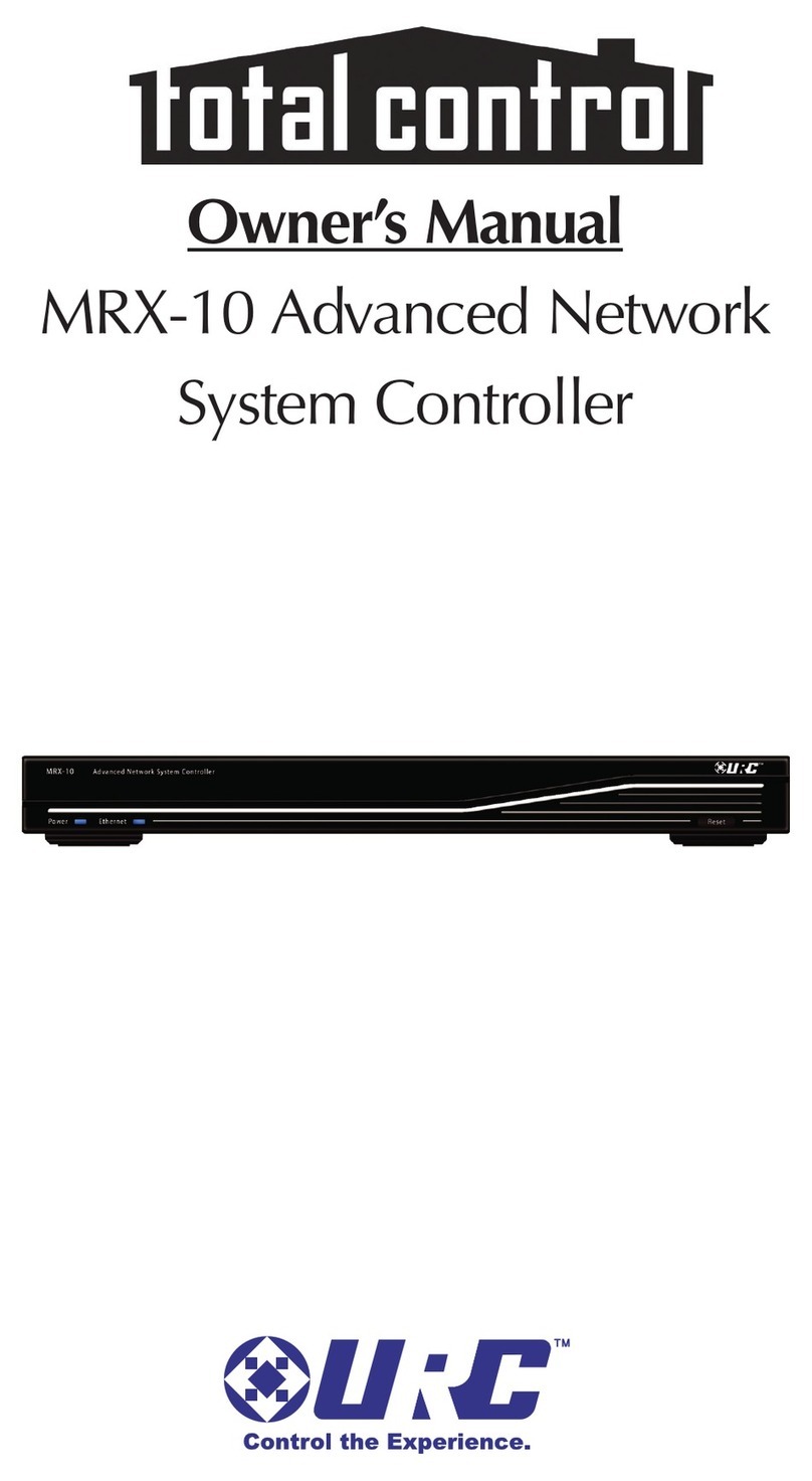
Universal Remote Control Complete Control MSC-400 Owner's manual

CCP Programming Manual
MSC-400 Master System Controller

CCP MSC-400 Programming Manual © 2009 Universal Remote Control,Inc.
The information in this manual is copyright protected.No part of this manual may be copied or reproduced in any
form without prior written consent from Universal Remote Control,Inc.
UNIVERSAL REMOTE CONTROL,INC.SHALL NOT BE LIABLE FOR OPERATIONAL,TECHNICAL OR EDITORIAL
ERRORS/OMISSIONS MADE INTHIS MANUAL.
The information in this manual may be subject to change without prior notice.
Complete Control is a registered trademark of Universal Remote Control,Inc.Entertainment Made Simple is a trade-
mark of Universal Remote Control, Inc. All other brand or product names are trademarks or registered
trademarks of their respective companies or organizations.
500 Mamaroneck Avenue
Harrison, NY 10528
Phone:(914) 835-4484
Fax:(914) 835-4532

INTRODUCTION 1
Product Features 2
What’s Included in the box 2
INSTALLING CCP ON VISTA OR XP 3
You Need a Personal Computer With a USB Port 3
Installing CCP and the USB Driver 3
KeepYour Database Up to Date — USE LIVE UPDATE 5
INTRODUCING CCP - THE COMPLETE CONTROL PROGRAM FOR MSC-400 AND MORE... 6
OVERVIEW OF THE NEW FEATURES OF CCP MSC-400 7
Configure Home 7
Properties Window 9
Model Designer Treeview10
CUSTOMIZING THE WORKSPACE 12
All Windows in the Default Layout can be resized 13
All Windows in the Default Layout can be Moved Around 13
Windows Grouping /Placement Icon 15
Using the Window Auto-Hide Features 16
PROGRAMMING TIPS 17
Complete Control Program MSC-400 17
i
M
S
C
4
0
0
M
A
S
T
E
R
S
Y
S
T
E
M
C
O
N
T
R
O
L
L
E
R
Table of Contents

Prior Programming Knowledge Required 17
Program Remote Control Devices First! 17
Use the Program Menu 17
Save a Device file and Import for faster programming 18
Save the MSC-400 File,Then Return to Remote Programming 18
STEP BY STEP – PROGRAMMING A TYPICAL MSC-400 SYSTEM 19
Options - New or Existing Files 19
New File - Step by Step 19
PROGRAM MENU STEP #1 - IMPORT REMOTE CONTROL DEVICES 22
PROGRAM MENU STEP #2 - DEVICES & ROUTING 23
Optional Step - Adding IR Devices 25
Adding RS232 Devices - Optional Step 26
Device Properties Window 26
PROGRAM MENU STEP # 3 - IR DATABASE 27
PROGRAM MENU STEP #4 - SERIAL TEMPLATE DATABASE 29
Programming and Saving RS-232 Devices 29
Manually Coding RS232 Commands 30
RS232 Repeat, Ramp Start and Ramp Speed 31
Embedding RS232 Commands in Smart Macros 32
ii
U
S
I
N
G
C
C
P
E
D
I
T
O
R
T
O
P
R
O
G
R
A
M
Table of Contents

iii
Type in SectionTitle
M
S
C
4
0
0
M
A
S
T
E
R
S
Y
S
T
E
M
C
O
N
T
R
O
L
L
E
R
PROGRAM MENU STEP # 5 - CREATING MACRO GROUPS AND SMART MACROS 33
Macro Groups 33
Adding a Macro Group and Smart Macros 34
Smart Macro Window 35
Programming Smart Macros 36
A Typical Smart Macro 36
Moving Commands in a Smart Macro 37
Recording RS232 Commands in Smart Macros 38
Converting RS232 Commands to a Smart Macro Group 37
Adding Delays To Smart Macros 38
Favorite Channel Macros 39
Programming IF/ELSE Statements 41
Programming Sensor Triggered Macros - Video and Voltage 44
Nesting a Smart Macro Alias 45
Toggle Macros 45
Action Variables 46
Can Variables get “Out of Sync”? 46
An Example of Action Variables at Work 47
Adding Relay Commands to Smart Macros 50
Embedding Relay Commands in a Smart Macro 50
Table of Contents

Creating a Macro Group for Relay Commands 52
Saving And Downloading A MSC-400 Project 54
Downloading a CCP MSC-400 Project 54
Dragging Triggers into CCP MX-6000 or MX-980 Editors 55
USING HYPERTERMINAL TO TEST ASCII RS-232 CODES 56
Introducing HyperTerminal 56
How to set up HyperTerminal 56
How to use HyperTerminal 59
Tips and Tricks 59
PC KEYBOARD EMULATION 60
To Program a Remote for PC Keyboard Emulation 60
PROGRAMMING MASTER/SLAVE SYSTEM 63
CONFIGURING MSC MASTER AND SLAVE CONTROLLERS 63
REFERENCE: FEATURES AND PARTS 65
General Information 65
MSC-400 Front Panel Features 65
MSC-400 REAR PANEL FEATURES 66
MSC-400 TOP PANEL FEATURES 67
RFX-250 RF SESNSOR 68
iv Type in SectionTitle
U
S
I
N
G
C
C
P
E
D
I
T
O
R
T
O
P
R
O
G
R
A
M

VS-1006 Voltage Power Sensor 69
VID-6 Video Sensor Cable 70
INSTALLATION 71
System Design 71
Device Control Capabilities And Behavior 71
User Preferences 72
MSC-400 Master System Controller 72
RFX-250 RF Sensor 72
VS-1006 Voltage Power Sensor 73
VID-6 Video Sensor Cable 73
CONNECTIONS 74
Video or Voltage Sensors (1-6) 73
ControlVoltage Out/Switched AC Out (VS-1006) 73
Current Sensing AC Outlet (VS-1006) 74
Composite Video (VID-6 Video Sensor Cable) 74
IR Programmable Outputs (1-6) 75
IR or RS232 Programmable Outputs (7-12) – IR 75
IR or RS232 Programmable Outputs (Ports 7-12) – RS232 75
IR In 76
RF In (RFX-250 RF Sensor) 76
v
Type in SectionTitle
M
S
C
4
0
0
M
A
S
T
E
R
S
Y
S
T
E
M
C
O
N
T
R
O
L
L
E
R

RF Out 77
USB2 Keyboard Emulation 77
Relay 1 77
NO (Normally Open) 77
NC (Normally Closed) 78
Relay 2 78
12V Out 78
12VDC 79
Master/Slave Systems 79
TROUBLESHOOTING 81
vi Type in SectionTitle
U
S
I
N
G
C
C
P
E
D
I
T
O
R
T
O
P
R
O
G
R
A
M

INTRODUCTION
Congratulations and thank you for purchasing the Universal Remote Control MSC-400 Master System
Controller. The MSC-400 enables a professional installer to provide the ultimate in predictable, reliable one
touch control of any audio video system.
One of the most common problems in home theater and whole-house entertainment systems is keeping the
system audio and video components “in sync” as different devices are selected (and turned on and off). The
MSC-400 knows exactly which components are on and off at any given time using a combination of compos-
ite video sensors, voltage sensors and discrete IR and RS232 power commands. The ability to send discrete
power commands or sense device status and properly send or not send power commands eliminates user con-
fusion completely.
With IR and RS232 command programmability and two built-in relays, system control is not just limited to A/V
devices. Virtually any device incorporated into a home entertainment system - including lifts, screens, drapes
and lighting - can also be controlled from the MSC-400.
When a MSC-400 system is programmed, something very different happens when the user presses a button on
an MSC compatible remote. Instead of sending a long string of commands in a remote control generated
macro that lasts several seconds (each step vulnerable to corrupting interference), the remote sends a unique
RF Trigger command in a few milliseconds. The MSC-400 receives the “trigger”, identifies it, and generates a
Smart Macro that is directly issued to the components via wired emitters, rear panel IR or RS-232 inputs and/or
relay controls. Since all commands are generated within the MSC-400, there is no possibility of any outside
interference corrupting any of the commands. Timing is perfect and there is no chance of a missed macro step.
The macro is “smart” because it can be programmed to make decisions on the fly. If a component is already
on, the video sensing circuit informs the microcontroller and the MSC-400 will skip the power on command
and any power-on delay. If a component is off, the macro is prefaced with a power on command and the nec-
essary power on delay. This accelerates operation when the system is already powered on, since power-on
delays are skipped. The final result as your client experiences it: seamless perfection with every button push.
The final result for you, the installer; predictable, reliable installations with clients that refer you to every friend
they have!
Programming an MSC-400 system is fast and simple using Complete Control Program. First, in the tab for the
remote control, you program the remote control exactly the way you have in the past, except that you do NO
Macro Programming. Once all IR codes are labeled and arranged the way you want, you save the file, switch
to the MSC-400 tab and import all the codes as “Connected Devices”. After setting the routing and adding any
RS-232 devices to the list of connected devices, you create a list of Smart Macro Names (Watch DVD, Watch
Cable TV, Turn System Off), then program the macros. After saving the file, you switch back to the remote tab
of CCS and drag in the triggers (labeled “Watch DVD”, “Watch Cable TV”, “Turn System Off”) into the correct
buttons on the remote. Download to the MSC-400 and the remote and you are ready to test your work.
This manual provides instruction for all aspects of installation, setup and programming a MSC-400 controlled
system.
Thank you again for purchasing the MSC-400 Master System Controller.
1
Introduction
M
S
C
4
0
0
M
A
S
T
E
R
S
Y
S
T
E
M
C
O
N
T
R
O
L
L
E
R

PRODUCT FEATURES
System Control of up to twelve devices (twenty two in a Master/Slave System)
Power management of up to six devices (twelve in a Master/Slave System)
MSC-400 stores and outputs all system commands and macros eliminating partially executed macros
MSC-400 Outputs IR and RS232 commands
Senses Composite Video and AC or DC voltage for device status
Six ConfigurableVideo or Voltage Sensor inputs
Six dedicated IR Output Ports (twelve in a Master/Slave System)
Six configurable IR or RS232 output Ports (ten in a Master/Slave System)
Rear panel USB Port allows control of a Windows Media Center PC
Remotes can be programmed to emulate Media Center Keyboard for alpha search
IR input for system control via properly programmed and compatible IR remotes and keypads
Narrow-band RFX-250 Sensor filters out interference from remote signals for reliable communication
and control
Up to three RFX-250 Sensors can be connected for extended RF Remote range in large systems
RF Output allows expansion to a second MSC-400 for control of up to 22 devices or connection to a
MRF Series Base Station for control of IR devices located away from the MSC-400
Two internal relays provide additional integration and control of screens, lifts, drapes, amplifiers, etc.
Relays are programmable for Paired Commands, (Normally Open or Normally Closed), Momentary
(Push and Hold) or Timed operation
12 volt ‘convenience’ output provides power supply to internal relays for devices that require voltage
for activation
Programmed with Complete Control Suite
Programmable to output single IR or RS232 commands
Programmable to output Smart Macros of IR and/or RS232 and Relay Commands
Programmable for ‘conditional’ IF/ELSE Smart Macros and Action Variables to output specific com-
mands for specific system settings or user preference
Programmable for Master System ON/OFF macros
Programmable for specific source select settings
Compatible remotes can be programmed with System Status Messages to let the user know when the
MSC-400 is executing Smart Macros and to wait for the macro to execute
What’s Included in the Box
1 – MSC-400 Master System Controller
1 – 12V DC 3.5A Power Supply
1 – RFX-250 RF Sensor
1 – 10’ RFX-250 Connecting Cable
6 – Standard IR Emitters
1 – 3’ USB Programming Cable
2Product Features
U
S
I
N
G
C
C
P
E
D
I
T
O
R
T
O
P
R
O
G
R
A
M

Installing CCP on Vista or XP PCs
You Need a Personal Computer With a USB Port
CCP will run on any Pentium II or faster Windows PC. Your PC should be equipped with an adequate amount
of RAM for the operating system you use. CCP is compatible with the Windows 2000, XP andVista operating
systems. It is not compatible with Windows ME, 98 or previous versions of Windows.
CCP is installed via a self extracting installer file downloadable from our installer only website:
www.urccontrolroom.com.
Installing CCP and Installing the USB Driver
CCP installs with a companion program for communication, Microsoft ActiveSync.You must install both pro-
grams and if un-installing, un-install both programs. To install the two programs, follow these steps:
1Connect to our installer only website www.urccontrolroom.com and navigate to Software
Downloads, then select CCP to download.
2A file download Window will open. Click on OPEN.
3The InstallShield Wizard Window for the CCP will open. Click on NEXT
4The Install Destination Window will then open. Click on NEXT.
5The Ready to Install Window will open. Click on INSTALL.
6The program will install and then show that installation has been completed. Click on FINISH.
7Now plug in the MSC-400 to the USB port. A Found New Hardware pop up will appear in the sys-
tem tray.
8Click on the Found New Hardware pop up. The Found New Hardware
wizard opens.
3
Installing
M
S
C
4
0
0
M
A
S
T
E
R
S
Y
S
T
E
M
C
O
N
T
R
O
L
L
E
R

4Type in SectionTitle
9Select No, not this time when asked “ Can Windows connect to Windows update to search for the
software?” Click Next.
10 When prompted “What do you want the wizard to do?” Select install from a list or specific location.
Click Next.
11 The next window will display “Please choose your search and installation options.” Select Don’t
search and click Next.
12 HIghlight the URC USB Sync MSC-400 & 500 driver. Click Next.
13 The Hardware Installation window opens with a message that this driver has not passed Windows
Logo testing. Click Continue anyway.
Installing
U
S
I
N
G
C
C
P
E
D
I
T
O
R
T
O
P
R
O
G
R
A
M

5
Type in SectionTitle
M
S
C
4
0
0
M
A
S
T
E
R
S
Y
S
T
E
M
C
O
N
T
R
O
L
L
E
R
14 A files needed window will follow. Click on the Browse button and navigate to C:\Program
Files\Universal Remote Control, Inc\Complete Control Program\MSC-400\drivers\Windows
XP\USB7210-2k.sys. Click Open then OK.
15 Once the driver finishes installing then click Finish.
KeepYour Database Up to Date — USE LIVE UPDATE
CCP includes a vast library of IR codes for hundreds of brands and models of A/V components. This database is
constantly growing with the inclusion of new devices every month. Keep your software up to date by using the
Live Update feature. Rather than un-installing and re-installing the software, you download updates to the
software from the internet. Simply follow these steps:
1Connect to the Internet normally.
2 Open CCP.
3 From the Communications Menu, select Live Update.
4In the Live Update window, click on “OK” to start the update prcoess. The process will automati-
cally close CCP.
5Wait for the progress window to indicate “Update Done”, then click on “OK”.
6 CCP is automatically restarted and ready to go.There is no need to restart Windows.
Installing

6Type in SectionTitle
Introducing CCP - The Complete Control Program for MSC-400 and more...
Menus and Shortcut buttons for common tasks. The Program Menu activates each task in the correct
order.
Home Designer and Model Designer Tree Views of the MSC-400 configuration. Double clicking on
any page enables you to quickly display that page on the simulator view. Right clicking on a device or
page activates a context menu.
The MSC-400 Simulate View is used to navigate and to select a button to program, edit or record a
macro.
Multi-tabbed Tool window allows access to the “IR Navigator”, “Button, Page and Device Properties”,
“Image Gallery”, “Sound Gallery” and “Serial Database”.
The tabs select whether you want Properties or one of the tools displayed in the window above.
The Macro window is used to view and edit macros.
Introducing CCP
A
B
C
D
E
F
Home
Designer
Model
Designer Simulate View
Macro
Window
A
BCD
F
Main Menu and Toolbar
Properties/
Tool
Window
Select via
Tabs (E)
E
U
S
I
N
G
C
C
P
E
D
I
T
O
R
T
O
P
R
O
G
R
A
M

7
Type in SectionTitle
M
S
C
4
0
0
M
A
S
T
E
R
S
Y
S
T
E
M
C
O
N
T
R
O
L
L
E
R
Overview of the New Features of CCP MSC-400
Complete Control Program represents a full house philosophy to programming, giving you tools to quickly pro-
gram multiple remotes and base stations in one file. In addition to a new philosophy, CCP also features a con-
figure home section to quickly build remotes and base stations to many rooms in a home, and also integrates
an indepth look at MSC400 connected Devices, Macro Groups, Smart Macros and a clickable simulator.
Configure Home
You’ll find tree view is now split into two areas, one area called House
Designer, which enables you to select remotes or base stations based on what
room they are in.
To configure a remote or a base station, you must DOUBLE CLICK it in
Home Designer.
The selected remote or base station is then placed into the Model Designer
tree view. To configure properties or a particular remote control page, DOU-
BLE CLICK it in Model Designer.
Once a remote is selected, clicking on the Program tab will reveal the standard URC programming steps.
Simply move from left to right in sequence to program the remote completely.
To add new rooms, remotes or basestations to your file, you can either:
1Right Click on Home in House Designer and select Add Room.
This will open the System Configuration window.
OR
New Features

8Type in SectionTitle
2Click on the Program tab and select “Configure Home” (House Designer) from the far left of the
Program ribbon.
This will open the System Configuration window:
3Once the House Designer window is open, simply drag rooms to “Home”, then drag remotes and/or
base stations to each room as needed.
TIP - Don’t add remotes to rooms until your first remote is finished. When adding remotes, you can
copy the first remote you’ve done, which will save effort on your second remote.
8New Features
NOTE: Drag remotes
or base stations on
top of the room to
add to room. You can-
not drag to the items
inside the room
directly.
U
S
I
N
G
C
C
P
E
D
I
T
O
R
T
O
P
R
O
G
R
A
M

9
Type in SectionTitle
M
S
C
4
0
0
M
A
S
T
E
R
S
Y
S
T
E
M
C
O
N
T
R
O
L
L
E
R
Properties Window
The Properties window is a new version of the Configuration Menu in the previous MSC Editor and is available
when selecting the various functions below. In the previous editor, the Configuration menu offered the options
of changing the MSC Basestation Name, selecting Master or Slave, an ID for a Primary/Secondary base, config-
uring and describing the video and voltage sensors, and configuring the serial port device, baud rate, data,
parity, stop bits and the description. It’s contents will differ according to the selection.
MSC-400 Simulator
1Click on the blue IR/RS232, video, voltage and RF ID ports of the MSC-400 simulator to access and
configure their properties windows.
3Make the appropriate changes to the properties windows displayed above.
9
New Features
M
S
C
4
0
0
M
A
S
T
E
R
S
Y
S
T
E
M
C
O
N
T
R
O
L
L
E
R
IR/RS232 Programmable
Ports RF In Video/Voltage Sensor
2The Properties windows will appear within the Properties/Tools menu. If the properties window is not
visible click on the property tab or go toView and check the Properties box.

10 Type in SectionTitle
Model Designer Treeview
1Within the Model Designer Treeview to the right, click on a
Connected Device, Macro Group, Smart Macro or the MSC-400.
2 Once the selection has been made it’s respective property
window will open and allow configuration.
3Configure the property windows as detailed shown below.
10 New Features
Model Designer
Connnected Device
MSC-400
Click on MSC400, a Device (Xbox), a
Macro Group (Source Select Macros) and
a Smart Macro (DVD 2).
Click on a device to change it’s name, port
id, and if it is a serial device designate it’s
Data Type as well as selecting whether or not
a carriage return is needed.
This property window gives the option to
rename the base station and informs you of it’s
current RFID as well as it’s Master or Slave des-
ignation.
U
S
I
N
G
C
C
P
E
D
I
T
O
R
T
O
P
R
O
G
R
A
M

11
Type in SectionTitle
M
S
C
4
0
0
M
A
S
T
E
R
S
Y
S
T
E
M
C
O
N
T
R
O
L
L
E
R
11
New Features
Smart Macro
Macro Group
In the Macro Group property win-
dow you can rename the Macro
Group and designate to which base
station or port the macro will be
sent to.
The smart macro property window
has the same features as the macro
group window with the exception
of the Macro Trigger Setting sec-
tion. This area allows for normal
macros or triggers to occur once a
device is sensed via a video or
voltage sensor.

12 Type in SectionTitle
Customizing the Workspace
CCP has some unique layout features that allow you to customize your own personal layout.
Here is the default layout: Home and Model Designer are on the left, the Simulator is in the middle, the
Properties window is in the upper right and the Macro window is in the lower right.
You can always get back to the default layout by using the “Default Layout” button in the “Window” tab.
Customizing theWorkspace
U
S
I
N
G
C
C
P
E
D
I
T
O
R
T
O
P
R
O
G
R
A
M
Other manuals for Complete Control MSC-400
1
Table of contents
Other Universal Remote Control Controllers manuals