manuals.online logo
Brands
  1. Home
  2. •
  3. Brands
  4. •
  5. Universal Tool
  6. •
  7. Impact Driver
  8. •
  9. Universal Tool UT8425R User manual

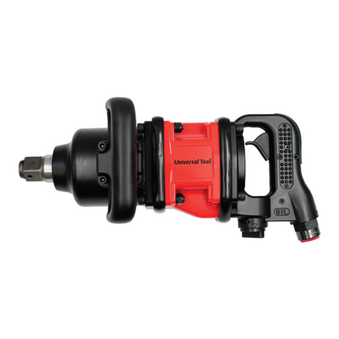
Universal Tool UT8425R User manual

Read these instructions carefully before installing, operating,
servicing or repairing this tool. Keep these instructions in a safe
accessible place.
Important
Operator Instructions
Includes - Foreseen Use, Work Stations, Putting Into Service, Operating,
Dismantling, Assembly and Safety Rules
Manufacturer/Supplier Product Type RPM
Cycles Per Min
Universal Air Tool Company Limited
Unit 8
Lane End Industrial Park
High Wycombe
Bucks
HP14 3BY
Tel No Fax No(01494) 883300 (01494) 883237
Model No/Nos Serial No
Product Nett Weight
lbs
Kg
Recommended Use Of
Balancer Or Support
Recommended Hose Bore
Size - Minimum
Recommended Max.
Hose Length
Ins M/M Ft M
Foreseen Use Of Tool
The impact wrench is designed for the tightening and loosening of
threadedfastenerswithintherangeasspecifiedbythemanufacturer.
It should only be used in conjunction with suitable impact type 1"
squarefemaledrivenutrunningsockets.Onlyusesocketswhichare
of the impact type.
Itisallowedtousesuitableextensionbars,universaljointsandsocket
adaptorsbetween thesquare outputdrive ofthe impactwrench and
the square female drive of the socket.
Donotusethe tool for any other purpose than that specified without
consulting the manufacturer or the manufacturer's authorised
supplier. To do so may be dangerous.
Never use an impact wrench as a hammer to dislodge or straighten
cross threaded fasteners. Never attempt to modify the tool for other
uses and never modify the tool for even its recommended use as a
nutrunner.
Putting Into Service
Air Supply
Useacleanlubricatedairsupplythatwillgiveameasuredairpressure
atthetoolof90p.s.i./6.3barwhenthetoolisrunningwiththetrigger
fully depressed and the air regulator in its maximum opening flow
position.Userecommendedhosesizeandlength.Itisrecommended
that the tool is connected to the air supply as shown in figure 1. Do
not connect a quick connect coupling directly to the tool but use a
whip or leader hose of say approximately 12 inches length. Do not
connect the tool to the air line system without incorporating an easy
to reach and operate air shut off valve. The air supply should be
lubricated. It is strongly recommended that an air filter, regulator,
lubricator (FRL) is used as shown in Figure 1 as this will supply clean,
lubricated air at the correct pressure to the tool. Details of such
equipmentcanbeobtained from your supplier. If such equipment is
not used then the tool should be lubricated by shutting off the air
supply to the tool, depressurising the line by pressing the trigger on
the tool. Disconnect the air line and pour into the intake bushing a
teaspoonful (5ml) of a suitable pneumatic motor lubricating oil
Work Stations
The tool should only be used as a handheld
hand operated tool. It is always recom-
mendedthatthe tool is used whenstanding
on the solid floor. It can be in other positions
but before any such use, the operator must
bein asecure positionhavinga firmgrip and
footing and be aware that when loosening
fasteners the tool can move quite quickly
away from the fastener being undone. An
allowance must always be made for this
rearward movement so as to avoid the
possibility of hand/arm/body entrapment.
1" Square Pistol Grip
Impact Wrench
UT8425R Std Anvil
UT8426 6" Ext. Anvil
4,000
1/2 13 30 10
Yes
24.8 (Std) 27.3 (Ext)
11.3 (Std) 12.4 (Ext)
Air Pressure
Recommended Working
6.3
bar
90
PSI
Recommended Minimum
n/a
bar
n/a
PSI
Maximum
7.0
bar
100
PSI
Personal Safety Equipment
Use - Safety Glasses
Yes
Use - Safety Gloves
Use - Safety Boots
Use - Breathing Masks
Use - Ear Protectors
Yes
Page No 1
Test Method Tested in accordance with Pneurop
test code PN8NTC1 and ISO Standard 3744
Vibration Level
Test Method Tested in accordance with ISO
standard 8662 Parts 1 & 7
(UT8425R) 4.9 Metres / Sec²
Noise Level UT8425R UT8426
Sound Pressure Level dB(A) 93.7 93.9
Sound Power Level dB(A) 105.5 105.5
(UT8426) 5.4 Metres / Sec²
Operating
The output of the impact wrench in prime working condition is
governed by mainly three factors
a) the input air pressure
b) the time the impact wrench is operated on the joint. Normal time
for joints of average tension requirement 3 to 5 seconds
c) the setting of the air regulator for a given joint at a given pressure
operated for a given time.
The air regulator item (19) can be used to regulate the output of the
impact wrench if no other control means is available. It is strongly
recommendedthatanexternalpressureregulatorideally aspart ofa
filter/regulator/lubricator(FRL)isusedtocontrolairinletpressureso
thatthepressurecanbe setto helpcontrol thetensionrequiredtobe
applied to the threaded fastener joint.
There is no consistent reliable torque adjustment on an impact
wrenchof this type.However, the airregulatorcan beusedto adjust
torquetotheapproximatetightnessofaknownthreadedjoint.Toset
the tool to the desired torque, select a nut or screw of known
tightnessofthesamesize,threadpitchandthreadconditionasthose
onthejob.Turnair regulatorto lowposition, applywrenchtonutand
gradually increase power (turn regulator to admit more air) until nut
movesslightlyinthe directionitwasoriginallyset.Thetoolisnowset
toduplicatethattightness,noteregulatorsettingforfutureuse.When
tighteningnutsnotrequiringcriticaltorquevalues,runnutupflushand
thentightenanadditionalone-quartertoone-halfturn(slightadditional
turning is necessary if gaskets are being clamped). For additional
power needed on disassembly work, turn regulator to its fully open
position. This impact wrench is rated a 1" bolt size. Rating must be
down graded for spring U bolts, tie bolts, long cap screws, double
depth nuts, badly rusted conditions and spring fasteners as they
absorbmuch of theimpact power. Whenpossible,clamp orwedge
the bolt to prevent springback.
Soak rusted nuts in penetrating oil and break rust seal before
removing with impact wrench. If nut does not start to move in three
to five seconds use a larger size impact wrench. Do not use impact
wrenchbeyondrated capacity as thiswilldrastically reduce tool life.
Note:Actual torqueona fastenerisdirectly relatedto joint hardness,
tool speed, condition of socket and the time the tool is allowed to
impact.
Usethe simplestpossible tool-to-socket hookup. Everyconnection
absorbs energy and reduces power.
Dismantling and Assembly Instructions
Disconnect the tool from the air supply.
Remove oil fill plug (38) from motor housing (1) and drain the oil into
asuitablecontainer.Remove4offscrews(54)with4offwashersand
takeoffdeadhandle(52)andhandleband(53).Remove4offscrews
withwashers(51)andpulloffhammerhousing(37)assembly.Press
out oil seal (39) and anvil bushing (40) from hammer housing (37).
Pull out anvil (47) or (47A) with anvil spacer (50). Take off and
separate hammer cage (41), pilot shaft (42), cam ball (43), hammer
cam(44),2offhammer pins(45)andcamrelease spring(46).o-ring
(48) and socket ring (49) may be prised off of anvil (47) or (47A).
Remove o-ring (36) from motor housing (1). Remove 4 off screws
with washers (35) and prise off end cap (34) with gasket (33). With
a soft metal (lead, aluminium, copper, etc.) hammer tap the splined
endofrotor (31) to drive rear endplate(26) assembly, rotor (31) and
6 off rotor blades (32) out of the rear end of motor housing (1). Look
at this time and note, for reassembly, the orientation of the two
exhaust holes in cylinder (29) i.e. the holes are positioned to the left
handsidewhenlookingfromtherearendofmotorhousing(1).Press
out front end plate (22) assembly and cylinder (29) assembly from
motorhousing (1). Donotremove 2 offguide pins (30) fromcylinder
(29)unlessreplacementsarerequired.Tapoutbearing(27)fromrear
end plate (26) but do not remove spring pin (28) unless a
replacementisrequired.Removeo-ring(23),oilseal(24)andbearing
(25) from front end plate (26). Drive out spring pin (3) and remove
trigger (2). Remove spring pin (21) and pull out reverse valve/air
regulatorassembly being careful notto lose lock spring(14) and ball
(15)frommotorhousing(1).Removeplug(20)andremovereversing
lever(19) andseparate airregulator (17),reversing valve(12), o-ring
(13) and o-ring (18). Do not remove spring pin (16) and spring (14)
and ball (15) from reversing valve (12) unless replacements are
required.Unscrewhoseadaptor(11)andtakeouto-ring(10),throttle
spring(9), valve ball(7), valve pin(6) and o-ring(5). Remove plug(4).
Reassembly
Cleanallpartsandexaminefordamage andwear. Replaceany parts
with parts obtained from the manufacturer or an authorised
representative.Checkallo-ringsforcutsandwear.Lookinparticular
for wear, damage and cracks on hammer cage (41), hammer cage
(42), ball (43), hammer cam (44), 2 off hammer pins (45) and anvils
(47)and(47A) particularly in theareaof the square drive. Ensurethat
the faces of end plates (22) and (26) that abut cylinder (19) are flat
andfreeformburrsandsurfacedefects.Ifnecessarylapfacesonaflat
find grade of abrasive paper. Coat all parts with a pneumatic tool
lubricating oil and assemble in the reverse order. On completing
assembly make sure all parts are locked tight and that anvil (47) or
(47A) is free to rotate and the trigger, reverse valve and regulator
valves operate freely. Remove oil fill plug (38) and pour into the front
end (40ml) of an SAE20 grade oil. Replace plug. Depress trigger (2)
and pour into the hose adaptor (11) 10ml (2 teaspoonfuls) of a good
quality pneumatic tool motor lubricating oil. Release trigger and
connect to a suitable oil supply. Run tool slowly for a few seconds to
allowtheoil to circulate. Set tool foroperationrequired - see Section
Operating.
preferablyincorporating arust inhibitor.Reconnect toolto airsupply
and run tool slowly for a few seconds to allow air to circulate the oil.
If tool is used frequently lubricate on daily basis and if tool starts to
sloworlosepower.Whenlubricating,alsoensurethatscreeninhose
adaptor (11) is clean.
It is recommended that the air pressure at the tool whilst the tool is
running is 90 p.s.i./6.3 bar. The tool can run at lower and higher
pressureswiththemaximumpermittedworkingairpressureof100
p.s.i./7.0bar.Foralowerairpressurethetoolwillgivealoweroutput
for a given setting of the air regulator set for 90 psi operation and an
increased output for higher pressures. Hence it is possible that
changesinsupply pressure can givesituationswhere the fastener is
under or over tightened. For changes in pressure, the regulator
position and application should be reassessed.
It is recommended that joint tightness of the threaded fastener
assembly be checked with suitable measuring equipment.
Page No 2
Safety Rules When Using an Impact
Wrench
1)Readalltheinstructionsbeforeusingthistool.Alloperatorsmustbe
fully trained in its use and aware of these safety rules. All service and
repair must be carried out by trained personnel.
2)Thesocketused must be ofthecorrect drive size and the"impact"
type. Never use sockets other than impact type.
3) Do not use sockets with excessive wear to the input and output
drives.Check thatthe squareon anyother typeof driveortheimpact
wrenchisnotcrackedor excessivelyworn beforefittingorchanging
socket,extension,etc.Makesurethatthesocketisfirmlyfixedtothe
tool.
4) Always ensure that a stable position or footing is adopted before
using the tool.
5) Ensure that the tool has been correctly set up on a test joint.
Incorrect set up could cause joint breakage with sudden and
unexpected movement of the tool.
6) Use only correct spare parts for repair.
7) Always ensure that the reverse valve is in the correct position
beforeoperatingthetool.Do notrunthetoolunless thesocketisfirst
located on the joint.
8) Check hose and fittings regularly for wear. Use quick connect
UT8425R
UT8426
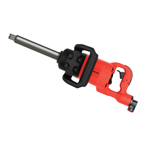
1" Square Drive Pistol Grip Impact Wrench - Std Anvil
1" Square Drive Pistol Grip Impact Wrench - Ext Anvil
Page No 3
Ref No Part No Description
1700531 Motor Housing
2731851 Trigger
3729006 Spring Pin
4731860 Plug
5731861 O-Ring
6700633 Valve Pin
7700636 Valve Ball
9700485 Throttle Spring
10 700487 O-Ring
11 700502 Hose Adaptor
12 732192 Reversing Valve
13 1008127 O-Ring
14 731858 Lock Spring (2)
15 731859 Steel Ball (2)
16 732206 Spring Pin
17 700007 Air Rgulator
18 731857 O-Ring
19 731855 Reversing Lever
20 732205 Plug
21 732197-1 Spring Pin
22 700532 Front Plate
23 700003 O-Ring
24 700012 Oil Seal
25 731837 Ball Bearing
26 700533 Rear Plate
27 731846 Ball Bearing
28 731845 Spring Pin
29 700534 Cylinder
Ref No Part No Description
30 700647 Spring Pin (2)
31 700535 Rotor
32 700536 Rotor Blade (6)
33 731847 Gasket
34 700630 End Cap
35 731850-1 Screw w/washer (4)
36 700004 O-Ring
37 700537 Hammer Housing (Steel)
38 732198 Oil Fill Plug
39 700143 Oil Seal
40 700141 Anvil Bushing
41 700134 Hammer Cage
42 700017A Pilot Shaft
43 700016 Cam Ball
44 700137-1 Hammer Cam
45 700136 Hammer Pin (2)
46 700138-1 Cam Release Spring
47 700139 Anvil (Standard)
47A 700140 Anvil (Extended)
48 731878 O-Ring
49 731879 Socket Ring
50 700147 Anvil Spacer
51 732199-1 Screw w/washer (4)
52 700637 Dead Handle
53 700538 Handle Band
54 700638 Screw 4)
55 700639 Lock Washer (4)
56 700545 Serial Number Plate
57 729343 Screw/Rivet (2)
Mar 1999 Ver 1.1 (KKFIT-98-00054)
Page No 4
Declaration of Conformity
Universal Air Tool Company Limited
Unit 8, Lane End Industrial Park, High Wycombe, Bucks, HP14 3BY, England
declare under our sole responsibility that the product
Models UT8425R/UT8426 1” SD Impact Wrenches, Serial Number
to which this declaration relates is in conformity with the following standard(s) or other normative document(s)
EN792 (Draft), EN292 Parts 1 & 2, ISO 8662 Parts 1 & 7, Pneurop PN8NTC1
following the provisions of 89/392/EEC as amended by 91/368/EEC & 93/44/EEC Directives
Place and date of issue Name and signature or equivalent marking of authorised person
Lane End D.H.Moppett (Man. Director)
This document may not be copied wholly or in part by anyone without the consent of the Directors of Universal Air Tool Company Limited
© Copyright of Universal Air Tool Company Limited, established in the United Kingdom, 1994
Designed & Written in the U.K.
Technical Specification
UT8425R UT8426
Overall Length 302 mm (11.9") 429 mm (16.9")
Width 111 mm (4.37")
Air Inlet 1/2" 14 NPT
Air Cons (Free) 60 SCFM (@ 90 PSIG)
Air Cons (Load) 38 SCFM (@ 90 PSIG)
Min Torque (5 Secs) 1300 ft lbs 1200 ft lbs
179 Kgm 166 Kgm
1763 Nm 1627 Nm
Operational Torque 600-1400 ft lbs 500-1300 ft lbs
82.8-193.2 Kgm 69-179.4 Kgm
813.6-1898.4 Nm 678-1763 Nm
Max Torque (30 Secs) 2800 ft lbs 2500 ft lbs
386 Kgm 345 Kgm
3797 Nm 3390 Nm
couplingsonly as recommended. See "Puttinginto Service". Do not
carry the tool by the hose and ensure that the hand is away from the
on/off valve when carrying.
9) Do not attempt to hold or guide the socket by hand when the tool
is running.
10) Do not exceed maximum recommended air pressure.
11) Use safety equipment as recommended.
12) The tool is not electrically insulated. Do not use where there is a
possibility of coming into contact with live electricity.
13) Preferably shut off the air supply before changing sockets or at
least ensure that the hands are well clear of the operating trigger.
14) Take care against entanglement of moving parts of the tool with
clothing, ties, hair, cleaning rags, etc.
15) When loosening fasteners first ensure that there is sufficient
clearance behind the tool to avoid hand entrapment. The tool will
move away from the threaded joint as the nut/bolt etc. is loosened
and rides up the thread moving the tool with it.
16)Onlyuseextensions,adaptorsanduniversaljointssuitableforuse
with impact wrenches.
17) If the tool appears to malfunction remove from use immediately
and arrange for service and repair.
Distributor
Notes
Accessories

This manual suits for next models

1

Other Universal Tool Impact Driver manuals

Universal Tool UT2147R-1 Manual

Universal Tool

Universal Tool UT2147R-1 Manual

Universal Tool UT150 Specifications

Universal Tool

Universal Tool UT150 Specifications

Universal Tool UT8355-R Specifications

Universal Tool

Universal Tool UT8355-R Specifications

Universal Tool UT8475C Manual

Universal Tool

Universal Tool UT8475C Manual

Universal Tool UT8160P-1 Manual

Universal Tool

Universal Tool UT8160P-1 Manual

Universal Tool UT8480C Manual

Universal Tool

Universal Tool UT8480C Manual

Universal Tool UT8095Q Manual

Universal Tool

Universal Tool UT8095Q Manual

Universal Tool UT8642C Manual

Universal Tool

Universal Tool UT8642C Manual

Universal Tool UT8027R Manual

Universal Tool

Universal Tool UT8027R Manual

Universal Tool UT8340C-2 Technical manual

Universal Tool

Universal Tool UT8340C-2 Technical manual

Universal Tool UT8030R User manual

Universal Tool

Universal Tool UT8030R User manual

Universal Tool UT8065R Manual

Universal Tool

Universal Tool UT8065R Manual

Universal Tool UT8120R User manual

Universal Tool

Universal Tool UT8120R User manual

Universal Tool UT8476C Manual

Universal Tool

Universal Tool UT8476C Manual

Universal Tool UT8090Q User manual

Universal Tool

Universal Tool UT8090Q User manual

Universal Tool UT8165R Manual

Universal Tool

Universal Tool UT8165R Manual

Universal Tool UT8176 Specifications

Universal Tool

Universal Tool UT8176 Specifications

Universal Tool UT2110R-1 Manual

Universal Tool

Universal Tool UT2110R-1 Manual

Universal Tool UT8025R-1 User manual

Universal Tool

Universal Tool UT8025R-1 User manual

Universal Tool UT8641C Manual

Universal Tool

Universal Tool UT8641C Manual

Universal Tool UT2025R Manual

Universal Tool

Universal Tool UT2025R Manual

Universal Tool UT8070R-1 Manual

Universal Tool

Universal Tool UT8070R-1 Manual

Universal Tool UT8085R User manual

Universal Tool

Universal Tool UT8085R User manual

Popular Impact Driver manuals by other brands

Milwaukee 2656-20 Operator's manual

Milwaukee

Milwaukee 2656-20 Operator's manual

Worx WX290 user manual

Worx

Worx WX290 user manual

Hitachi KC10DFL - Lithium Ion Combo user manual

Hitachi

Hitachi KC10DFL - Lithium Ion Combo user manual

Chicago Pneumatic CP7776 Operator's manual

Chicago Pneumatic

Chicago Pneumatic CP7776 Operator's manual

Urrea UPC727 quick start guide

Urrea

Urrea UPC727 quick start guide

Berner 109416 instruction manual

Berner

Berner 109416 instruction manual

NOCRY NIW-400NM instruction manual

NOCRY

NOCRY NIW-400NM instruction manual

Makita TD111DZJ instruction manual

Makita

Makita TD111DZJ instruction manual

Makita DTD152 instruction manual

Makita

Makita DTD152 instruction manual

Makita BTP131RFE instruction manual

Makita

Makita BTP131RFE instruction manual

SW-Stahl S3266 quick start guide

SW-Stahl

SW-Stahl S3266 quick start guide

Parkside PDSSE 550 A1 Translation of the original instructions

Parkside

Parkside PDSSE 550 A1 Translation of the original instructions

RIDGID R862312 Operator's manual

RIDGID

RIDGID R862312 Operator's manual

Yokota YW-90C manual

Yokota

Yokota YW-90C manual

Makita 6916FD instruction manual

Makita

Makita 6916FD instruction manual

GRAPHITE PRO 59GP402 instruction manual

GRAPHITE PRO

GRAPHITE PRO 59GP402 instruction manual

DeWalt DCF889 instruction manual

DeWalt

DeWalt DCF889 instruction manual

kincrome K13202 manual

kincrome

kincrome K13202 manual

manuals.online logo
manuals.online logoBrands
  • About & Mission
  • Contact us
  • Privacy Policy
  • Terms and Conditions

Copyright 2025 Manuals.Online. All Rights Reserved.