www.up-board.org /www.up-shop.org / www.up-community.org
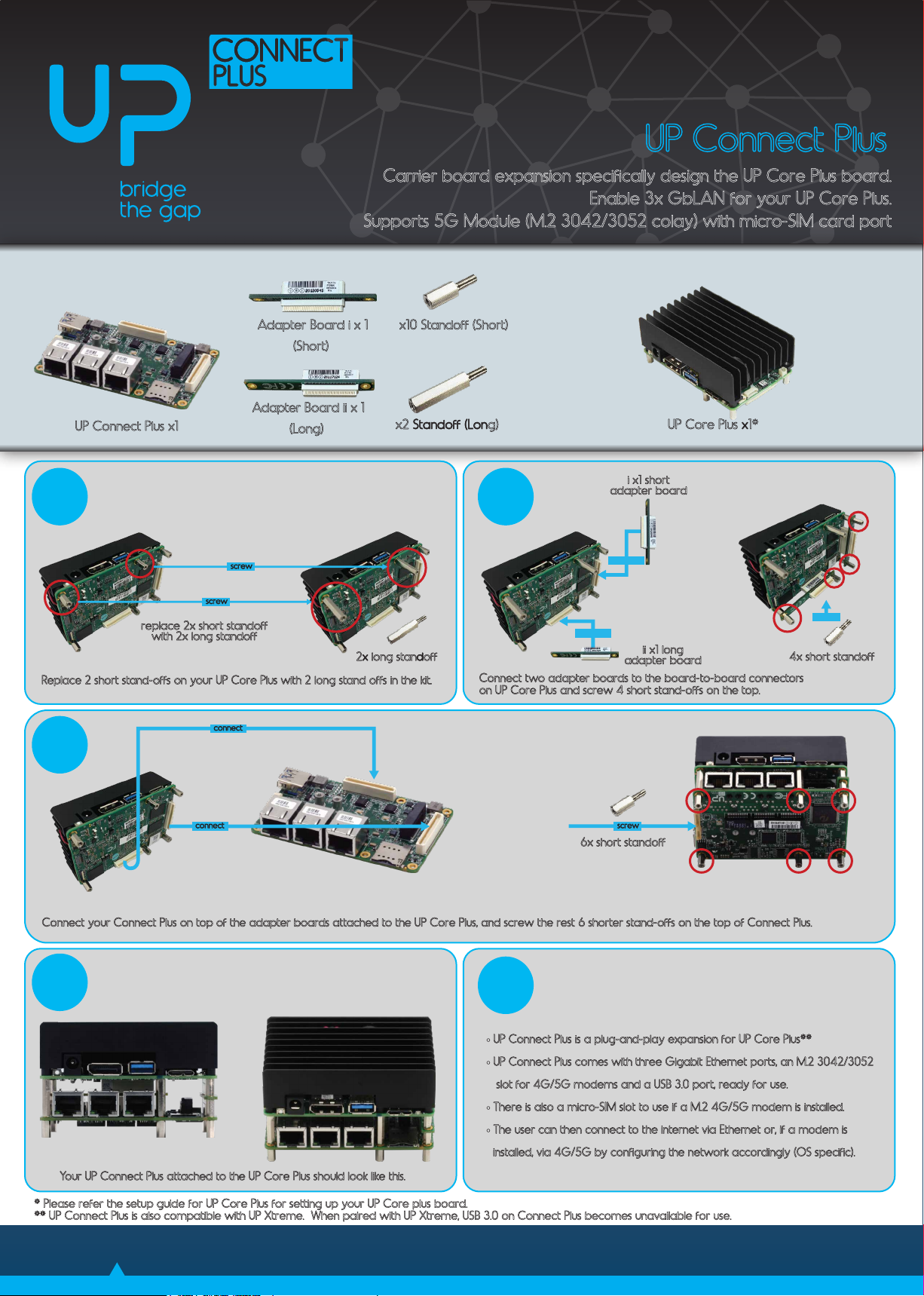
* Please refer the setup guide for UP Core Plus for setting up your UP Core plus board.
** UP Connect Plus is also compatible with UP Xtreme. When paired with UP Xtreme, USB 3.0 on Connect Plus becomes unavailable for use.
Please read the following safety instructions carefully
It is advised that you keep this manual for future references
1. All cautions and warnings on the device should be noted.
2. Make sure the power source matches the power rating of the device.
3. Position the power cord so that people cannot step on it. Do not place
anything over the power cord.
4. Always completely disconnect the power before working on the system’s
hardware.
5. No connections should be made when the system is powered with a sudden
rush of power as it may damage sensitive electronic components.
6. If the device is not to be used for a long time, disconnect it from the power
supply to avoid damage by transient over-voltage.
7. Always disconnect this device from any power supply before cleaning.
8. While cleaning, use a damp cloth instead of liquid or spray detergents.
9. Make sure the device is installed near a power outlet and is easily accessible.
10. Keep this device away from humidity.
11. Place the device on a solid surface during installation to prevent it from
falling.
12. Do not cover the openings on the device. This is to ensure optimal heat
dissipation.
13. Keep an eye for high temperatures when the system is running.
14. Do not touch the heat sink or heat spreader when the system is running
15. Never pour any liquid into the openings. This could cause re or electric
shock.
16. As most electronic components are sensitive to static electrical charge, be
sure to ground yourself when installing internal components to prevent static
charge. Use a grounding wrist strap and contain all electronic components in
any static-shielded containers.
17. If any of the following situations arise, please contact our service personnel:
I. Damaged power cord or plug
II. Liquid intrusion through the device
III. Exposure to moisture
This device complies with Part 15 FCC Rules. Operation is subject to the
following two conditions:
(1) this device may not cause harmful interference, and (2) this device must
accept any interference received including interference that may cause
undesired operation.
Caution: There is a danger of explosion if the battery is incorrectly replaced.
Replace only with the same or equivalent type recommended by the
manufacturer. Dispose of used batteries according to the manufacturer’s
instructions and your local government’s recycling or disposal directives.
FCC Statement
Regulatory
Safety Precaution
Component Name
Hazardous or Toxic Materials or Elements
Lead (Pb)
Mercury (Hg)
Cadmium (Cd)
Hexavalent
Chromium (Cr(VI
Polybrominated
biphenyls (PBBs)
Polybrominated
diphenyl ethers
(PBDEs)
PCB and Components 0 O O O O O
Wires & Connectors for
Ext. Connections 0 O O O O O
This form is prepared in compliance with the provisions of SJ/T 11364.
O: The level of toxic or hazardous materials present in this component and its parts is below the
limit specified by GB/T 26572.
X: The level of toxic of hazardous materials present in the component exceed the limits specified
by GB/T 26572, but is still in compliance with EU Directive 2011/65/EU (RoHS 2).
Notes:
1.
The Environment Friendly Use Period indicated by labelling on this product is applicable
only
to use under normal conditions.
Product specifications
China RoHS Requirements
Copyright © 2020 AAEON Europe B.V. All rights reserved. UP is a registered trademark of AAEON Europe B.V. Specifications are subjective to change without notice.
Intel, Movidius and Myriad are trademarks of Intel Corporation or its subsidiaries in the U.S. and/or other countries. Other brands and product names are trademarks or
registered trademarks of their respective holder
UP Community
https://www.up-community.org
UP Wiki
https://wiki.up-community.org/Carrier_boards
UP Downloads
https://downloads.up-community.org
QUESTIONS?
REACH US HERE
!
Ethernet
x Intel® Ethernet Controller I211-AT (or with I210-IT with TSN and
wide temperature support)
Power Supply Type 12V DC from the main board
Power Consumption 13.5W(Max) (Only UP Connect Plus)
Approximately 36 to 40 Watts (UP Core Plus + UP Connect Plus)
Dimensions (L x W) 90 mm x 56 mm
Operating
0~60°C
Operation Humidity 10%~80%RH, non-condensing
Certication CE/FCC Class A
Linux: Ubuntu, Yocto Android-IA 9.0
Ethernet 3x RJ45 Ethernet port
USB 1x USB 3.0 on the side (UP Core Plus only)
PCIe Switch 1x 2 channel PCIe Switch
5G Module (M.2 3042/3052 colay)
1x Micro SIM CARD(Push/Push)
1x Docking Connector 1
COM1 Connector(UP Core Plus only)
SPI Connector(UP Core Plus only)
OS Support
Internal I/O Ports