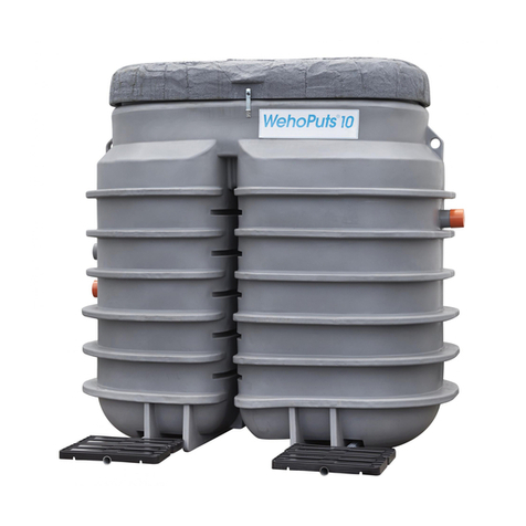
Uponor Clean II User manual

Uponor Clean II
Treatment Plant
Operating Manual
2/2023

We reserve the right to make changes.
Sludge emptying Indoor display panelChemical lling Control centre
Puried
wastewater
Inlet
Uponor Clean II treatment plant for wastewater for up to 10 PE.
Contents
1. Overview..................................................................................................... 3
2. Installation and dimensional drawings.............................4
3. Technical information......................................................................5
4. Installation.................................................................................................6
5. Setting up the wireless alarm system ................................11
6. PlantCare...................................................................................................12
7. Operation ..................................................................................................12
8. Operating principles ........................................................................16
9. Maintenance..........................................................................................19
10. Malfunction..............................................................................................21
11. Contact information........................................................................23
Service Log............................................................................................. 24
2 | Uponor Clean II Treatment Plant Operating Manual

The biochemical Uponor wastewater treatment plant
is a domestic wastewater treatment system intended
for continuous household use, or for a second home
equipped for year-round, regular use. The Uponor
treatment plant processes all wastewater in a
household (from bathing, dishes, laundry, and toilet
ushing). It is suitable for all kinds of building lots,
including those that are small or rocky.
Foreign objects and materials must not be washed
down into the treatment plant, such as debris for
solid waste disposal or materials that are classied
as problem waste, which can endanger the biological
processing of the treatment plant.
Operating principle
The Uponor Clean II wastewater treatment plant
represents top technology in wastewater treatment.
Because of its new design, the treatment plant has
compact outer dimensions. After installation of the
treatment plant, only three unobtrusive covers are
visible in the yard.
The treatment plant is primarily designed for use
by two households. With a holiday automation
technology, it is also suitable for summer cottages
that are used frequently year-round. Thanks to
the holiday automation, the treatment plant can
withstand breaks, as the active sludge is sustained
by continued aeration and recycling. The treatment
plant is installed in the ground and the extension
pipes can easily be extended.
The treatment plant is a biochemical wastewater
system, where all household sewage can be directed.
The cleaning process works on a batch principle,
with an active sludge process and a chemical
occulation. The wastewater is treated in equal
batches, so that each batch is puried to the same
extent. Microbes living in the active sludge complete
a biological purication, while the phosphorus
compounds are removed from the wastewater by
chemical precipitation. At the end of the cleaning
process, the puried water is pumped out, for
example, into an open ditch, drainage well or ditch
that serves as a discharge point.
1. Overview
Cleaning process cycle:
• pre-settling of wastewater, storage of incoming wa-
ter and storage of the sludge in the septic tank
• lling of the process tank
• aeration
• dosage and mixing of the occulation chemical
• rst settling
• excess sludge is returned to the septic tank
• second settling
• discharge of the puried water
If no water is entering the plant, the process is in a
waiting or holiday cycle, in which the wastewater is
regularly aerated in the process tank. The aeration
keeps the microbes active in the process tank.
The Finnish Environment Institute SYKE has completed
standard CE testing on the Uponor wastewater
treatment plant. The results of the test are excellent
and well above the requirements.
The treatment plant is easy to use. The Clean
occulation chemical is added into the plant a few
times a year, and the sludge emptying truck comes
to empty the sludge accumulated in the septic
tank at least once a year. Electric consumption is
low primarily because of the mammoth pumping
technique. The wastewater and sludge are
transferred without mechanical pumping. The air
used in the process is produced by blowers located
underneath the second cover of the control panel.
The treatment plant has a wireless alarm system,
visible through an Info panel installed inside the
house. An indicator light on the Info panel indicates
when it is time to ll the chemical vessel, if the water
level in the tank is too high, if there is a technical
malfunction or when the septic tank must be
emptied. A test button can be used to query the
state of the plant activity. The activity can also be
controlled and followed with a mobile device using a
PlantCare mobile bookmark.
NOTE! PlantCare program uses treatment plants
local network and local web browser. It is not
connected to internet.
Uponor Clean II Treatment Plant Operating Manual | 3

2. Installation and dimensional drawings
Anchoring
Accessories:
SYSTEM DESCRIPTION:
Frost insulation
Soiltreatment.......m²
Extension pipes Ø 560 with sealing ring Infilrtration chamber
Outlet:
Ditch
ml/d (max 2100 l/d)Dim. water volym ..................
PENumber of persons ..................
Ditch
Ø110
Inlet
Ø110
mm/yRuntime ..................
Sewer
Notice
from the tank top to the ground.
Max installation depth 1 m
Clean II (Uponor code 1133828) + Uponor Sample Chamber 315 (uponor code 1003559).
Two family houses (4-10 persons), domestic wasterwater
Sample chamber 315
We reserve the right to changes.
Designer: name, date and signature
Lot/Rno.
Construction act
Construction site: name and address
City/Village Block/Yard Notes from administrative authority
Planning, work no. and drawing no.
Drawing type
Qualifies
Modification
Number
Scale
1175
1225
2355
3295
1916
2135
450
max 1m
4 | Uponor Clean II Treatment Plant Operating Manual

Uponor Clean II treatment plant Monitoring functions
Product information
Uponor number 1133828
LVI number 3624861
EAN code 6414900301565
Measurements
Width, mm 2355
Length, mm 3295
Inlet connection height, mm 1225
Outlet connection height, mm 1175
Height with extension pipe, mm 2135
Transport height, mm 2135
Weight, kg 450
Fitting size, mm 110
Septic tank volume, m34,6
Process tank volume, m32,2
Total volume, m36,8
Electricity
Electric connection 230V 1~ phase, 10 A fuse
Flow data
Standard ow, l/day 1500
Maximum ow, l/day 2100
Batch size, l 350
Pump-out time, min 16
Occupancy 3–10
Operating costs
Chemical consumption per year, l 60–120
Chemical consumption/batch, dl 1,0
Electricity consumption per day, kWh 1,6
Electricity consumption per year, kWh 584
Sludge removal At least once a year
Installation conditions
Installation depth from inlet sewer
to the ground, max. 1,2 m
Installation depth on top of the tank, max. 1,0 m
Extension pipe Ø 560 mm
Accessories Uponor
number LVI
number
Uponor anchoring system 1003563 3625391 4 pcs
Uponor settling chemical
(aluminium chloride) 1003575 3624997 15 l
Clean extension pipe 560 x 1 m 1057363 3625015 3 pcs, with
installation
depth > 0,7 m
Extension pipe seal 560 1003600 2521817 6 pcs
Sampling well 1003559 3625090
3. Technical information
Connection to the treatment plant
Display panel indicators
OK indicator light
Everything in working order
Septic tank full
Order a sludge emptying truck
Possible hardware malfunction
Call a service technician
High water level
Chemical running out
Fill the chemical vessel (20 l)
Uponor Clean II Treatment Plant Operating Manual | 5

Trench
When measuring the length and width of the trench,
allow for a workspace of at least half a metre around
the tank. In normal installations, the depth of the
trench for treatment plants is approximately 2 metres.
For deeper installation, see the text for “Extending
riser pipes”.
If the treatment plant is installed in dense soil or in
an area with high groundwater levels, the treatment
plant must be anchored. Allow for a space of at
least 60 cm measured from the outermost edge
of the treatment plant. Make sure that the trench
has underground drainage, so that any water that
accumulates there does not put a strain on the tank.
This also helps to anchor the tank. Install a cable
protection pipe between of the treatment plant and
the building’s main distribution board, in which the
electrical cable can be installed. Mark according to
requirements.
Remember that the distance between the plant
control centre and the Info panel inside the house
must not be more than 60 metres, but it is advisable
to install the display panel as close as possible to the
treatment plant. Do not place the display panel in a
location where buildings or other obstacles can block
the wireless connection.
During the installation, it is recommended to ll the
septic and process tank with water. The lled tank
stabilises the plant and prevents it from rising in the
trench if water is accumulated there.
Anchoring
The treatment plant must be anchored if it is installed
in dense soil, such as clay or silt soil, or if the ground-
water level is high. The Uponor anchoring system
can be used to anchor the treatment plant (see
Uponor anchoring system installation instructions).
In a trench dug into clay or cliffy surface, provide
drainage to prevent any surface water that enters
the trench from collecting and subjecting the tank to
pressure.
4. Installation
Contents of the package:
The treatment plant is delivered ready for
installation. Parts of the treatment plant are
described on page 16.
Inside the treatment plant you will also nd an
accessory box: 2 ttings, 110 mm inlet pipe, display
panel and power supply, owner’s manual, safety
goggles and gloves.
Please note when installing and positioning the
treatment plant:
• Distance to trafc areas
• Drainage of the treatment plant trench
• Install the treatment plant as close to the ground
level as possible
• Compress the bottom of the trench and anchor
the treatment plant according to the installation
instructions, plant type and anchoring instruc-
tions
• Protect the treatment plant and sewer pipes
from freezing with frost insulation if necessary
• Shape the ground so that surface water is di-
verted away from the treatment plant
• Follow the wastewater plans made by the local
wastewater management
Uponor anchoring
system product
number 1003563
6 | Uponor Clean II Treatment Plant Operating Manual

100mm
INSTALLATION
Trench bottom pre-work
h = 30 cm
h = 30 cm
h
h
Backlling and anchoring
• Make a 100 mm layer of stoneless sand or gravel on the bottom of
the trench
• Level and compress it
• Lift the tank to the bottom of the trench.
Check that the height is right, and the tank is level
• Anchor the tank if there is risk of high groundwater.
Use 4 pcs of Uponor anchoring systems (1003563)
• Backll the cavity with stoneless sand or gravel in
300 mm layers, compress the layers, ll up the tank with
water in the same pace with the backlling
Connections
h = 30 cm
In Out
• Connect the inlet and outlet 110mm pipes
• Connect power mains to the connection box
Uponor Clean II Treatment Plant Operating Manual | 7

h = 30 cm
Opt.
h = 30 cm
1.
2.
1. 1.
2.
3.2.
Final backlling
If there is reason to assume that the frost penetrates
deep into the ground, protect the tanks and other
areas prone to freezing with a thermal insulation board
(e.g., with a 100 mm thick foam). In the winter, the snow
covering the treatment plant and sewer line should
not be removed, except for maintenance work. Fill the
trench. Shape the ground so that the surface water is
directed away from the tank. Leave a space of about
10 cm between the cover and the ground to ensure the
operation of the wireless alarm and the supply of air
inside the control centre.
EXTENDING RISER PIPES
1. Emptying and cutting the risers
• Backll the rest of the trench. Do not compress with
machine on top of the tank • Shape the soil surface to guide surface waters away
from the tank
• Remove the lids
• Disconnect the air-intake hoses from the of the switch
cabinet and compressor unit (PIC 1)
• Lift switch cabinet and compressor unit and disconnect
the air hoses from their underside and lift them out
(PIC 2)
• Disconnect the air hoses from the chemical vessel and
lift the vessel out (PIC 3)
• Cut the neck of the shaft with a saw along its middle,
marked “ofine”
Air hose removal
1.&2. Use a screwdriver
to remove the
mounting strap
3. Pull the air hose.
8 | Uponor Clean II Treatment Plant Operating Manual

h = 30 cm
2.
3.
1.
20 cm
20 cm
2. Installation of extension pipes
• Place a rubber-sealing ring around each end of the pipe.
Lubricate the sealing ring.
• Push one end of the extension pipes into the sawn risers.
Push them all the way to the bottom of the sockets
• Push the top part of the riser on the other end of the
extension pipe. Push them to the bottom of sockets.
h = 30 cm
3. Mounting chemical vessel, switch cabinet and lids
• Connect the air hoses to the chemical vessel and lift the
vessel in A
• Connect the air hoses to the bottom of the switch cabi-
net and compressor unit, and lift them to the riser
• Connect the air-intake hoses to the switch cabinet B and
compressor unit C
• Connect the lids
Air hose mounting
1. Connect the air hose
to the mounting part
2. Lock the mounting
strap.
Uponor Clean II Treatment Plant Operating Manual | 9

h = 30 cm
4. Final backlling
• Backll the rest of the trench. Do not use compress with machine on top of the tank
• Shape the soil surface to guide surface waters away from the tank
Connecting the supply cable
1
3
Have an electrician to connect the power cable to the
connection box. The cable must have a residual current
circuit breaker. Overvoltage protection is recommended in
lightning-sensitive areas.
Supply 230 V AC 50 Hz, max. fuse 10 A
Fill the chemical vessel with the Clean Flocculent (30 litres).
Wear protective gloves and goggles when handling the
chemical. For detailed information on the occulation
chemical, see the enclosed safety data sheet or our website
www.uponor.com/-, www.uponor.com/sv-se.
The treatment plant is ready for use.
Q1
L1
N
PE
1 001 brown
43 009 blue
2
2
10 | Uponor Clean II Treatment Plant Operating Manual

5. Setting up the wireless alarm system
4
Lock the treatment plant cover. The sewage treatment system is
ready for use.
To ensure a correct cleaning result and trouble-free
operation, a few more steps must be taken before
starting the treatment plant.
Info panel placing
Mount the Info panel in a planned nearby location
inside the house. Remember that the distance between
the control centre and the Info panel should not exceed
50 metres. However, it is advisable to install the display
panel as close as possible to the treatment plant.
Do not place the display panel where buildings or
similar obstacles can block the wireless connection
Setting up the wireless connection
Range test
With the help of the radio connection range test, it is
possible to nd a suitable location for the display panel
inside the property. The range test starts automatically
after a successful pairing of Control Unit and Info Panel.
1. The range test can be used to verify that the radio
reception is good at the display panel installation
site. During the test, three colours of LEDs may ash
on the display panel:
• Green = good connection
• Yellow = connection moderate
• Red = poor connection or no connection at all
2. The range test ends automatically after 15 minutes.
The test can also be interrupted by pressing the OK
button on the display panel or the test button on the
control centre.
If you want to make a new range test, you have to un-
pair the Info panel rst. It can be done during 10 min
after power-on by pressing and holding the OK button
for 10 sec. A new range test can be started by following
the steps in Setting up the wireless connection.
NOTE! If no connection is established, the wireless
connection light turns red. In this case, reconnect
the wireless connection as described above. If the
wireless connection fails after several attempts,
try relocating the display panel. Make sure that
the distance between the control centre and the
display panel is not too long and that buildings, for
example, do not obstruct the radio signal.
3
After 5 seconds, the signal light of the wireless connection starts
blinking and the connection is established. This takes 5-10 seconds,
after which the signal light turns off and the green OK light turns on.
2
Turn on the Info panel by connecting to the AC adapter. Pairing can
be activated during the rst 5 min. Start pairing by pressing and
holding the OK button for at least 5 seconds.
Connect the AC adapter to the wall outlet and the Info panel. Pairing
can be activated during the rst 5 min. Start pairing by pressing and
holding the OK button for at least 5 seconds.
1
Turn on the control centre by plugging the power cable. so that the
Info panel is not turned on. The control unit will then start pairing to
search for the display panel for up to 5 minutes to establish a wireless
connection (“P - - -” will appear on the control unit display).
NOTE! The following steps must be performed
without interruption for successful deployment.
Uponor Clean II Treatment Plant Operating Manual | 11

7. Operation
6. PlantCare
The daily operation of the treatment plant is monitored by means
of an indoor display panel (1). A control centre (2) is located inside
the treatment plant. The status of the treatment plant can be read
in more detail from the Uponor PlantCare mobile bookmark (3).
2
1 3
The treatment plant activity can be followed with
a mobile phone or other mobile device using a
PlantCare mobile bookmark. In order to connect the
mobile device to the treatment plant you have to be
close to the plant, within the range of Wi-Fi net.
NOTE! PlantCare program uses treatment plants
local network and local web browser. It is not
connected to internet.
Connecting to PlantCare
1. Connect to Wi-Fi
Go near the treatment plant. Search with your mobile
device the Wi-Fi of the plant. Select the Wi-Fi which
starts with UPONOR.
Wi-Fi password is the network last part of the WLAN id
in reverse. E.g., If the ID of the network is
UPONOR_WWT_AC617111 –network,
the password is 111716CA.
If there are problems in joining, close all browser
pages.
2. Open PlantCare
Open the browser and select address
uponor.plantcare.net
12 | Uponor Clean II Treatment Plant Operating Manual

Info panel
The Info panel and the treatment plant control centre
are connected wirelessly. The range of the wireless
connection is 60 metres.
3
To detach the Info
panel from the wall
bracket, press on the
top, for instance, with a
screwdriver tip.
1
Screw the Info
panel wall bracket
to a wall inside the
property.
2
Plug the Info panel
into an electrical
outlet through the
included AC adapter
and mount it in a
wall mount.
The alarm function of the info panel
The display panel has four alarm functions that are
activated in the event of a fault. With an activated
alarm, the info panel works as follows:
1. The green OK light turns off.
2. The red fault indicator light will start ashing and
the alarm will sound (the beeper will sound for 30
seconds per hour).
3. Press the OK button to acknowledge the alarm. The
alarm light stops blinking and stays on. The signal
beeping goes off.
4. When the fault has been rectied, the indicator light
goes out and the green OK light comes on.
The reminder function of the Info panel
Clean II has two kinds of reminder functions; service
reminders and a sludge emptying reminder.
The Info panel indicates when it is time to make
periodical service (1-year, 3-year or 6-year-service)
and when it is time to empty the septic tank of the
sludge. It is recommended to make service within 3
months of the reminder. Sludge emptying must be
completed within one month of the reminder.
1. Sludge emptying reminder works as follows:
2. The yellow sludge truck light will start to ash and
the alarm signal will sound (the beeper will sound
for 30 seconds per hour). The green OK light is on.
3. To clear the sludge emptying reminder, press the
OK button, at which point the reminder light will
stop ashing and remain on. The alarm sound goes
off. When the septic has been emptied, reset the
reminder function by pressing the test button on the
control centre. Press the test button for more than 10
seconds, and E000 is displayed on the control panel.
The sludge truck light on the display panel goes off.
Wireless connection
OK button to acknowledge alarms
Reminder to empty the septic tank
Hardware failure in the control enter
High water level
Low level of the settling chemical
Normal mode without errors (green light)
Info panel indicators.
The Info panel has the following functions:
• Four alarm symbols
• Green OK light
• One reminder symbol
• OK/reset button
Service reminder works as follows:
1. The exclamation mark light starts to ash in yellow
and the alarm signal will sound (the beeper will
sound for 30 seconds per hour). Same time on the
control unit display appears the error code E401,
E402 or E403 depending on the reminder type.
2. To acknowledge the service reminder, press the OK
button, at which point the reminder light will stop
ashing and remain on. The alarm sound goes off.
3. After the service has been carried out, reset the
reminder function by pressing the test button on the
control centre when there is the error code of the
reminder on the display. Press the test button for
more than 5 seconds, and the error code ashes on
the display and then disappears. The exclamation
mark light on the Info panel goes off.
Uponor Clean II Treatment Plant Operating Manual | 13

Info panel settings
There are three switches on the back of the info panel
that can be used to set the following functions:
Switch 1. Alarm on/off
The upper toggle switch is used to select whether the
signal sound is on or off in the event of an alarm.
Switch 2.
Not in use with Clean II.
Switch 3. Sludge emptying reminder
The lower dip switch is used to activate or deactivate
the sludge emptying reminder. If the treatment plant
is covered by regular municipal septic emptying, for
example, the reminder function can be switched off.
Control unit
The control unit is in the treatment plant under the
cover of the process tank. The control unit has a display
from which the batch counter value can be read, the
status of the treatment plant can be checked and a
possible error code can be read. Outside the control
centre, there is a test button that can be used to
activate the treatment plant status display, start a test
program and reset the sludge emptying reminder
Normal operation
In a normal situation, the display shows the batch
counter value.
Malfunction
The display alternates between the batch counter value
and the error code. See page 21 for operation during
a malfunction. If several faults are active at the same
time, their error codes are displayed in sequence.
Treatment plant status
The display shows the stage of the cleaning cycle in the
treatment plant. The status display is initiated by briey
pressing the test button (for less than 5 seconds). The
display shows S and a series of numbers. The code
indicating the status of the treatment plant is displayed
for 30 seconds, after which the display returns to the
batch counter value.
Test cycle
The treatment plant has a test cycle that can be
used to check the operation of the various units in
the treatment plant. In order to see in the tank before
starting the test cycle, lift up switch cabinet and
compressor unit out of their place. Be careful not to kink
the air hoses below them.
See where each unit is located in the process tank.
The test cycle is started by pressing the test button for
longer than 5 seconds but less than 10 seconds. When
the test button is fully pressed, the display will show the
seconds: _ _ _1, _ _ _2, _ _ _3, __ _4, S_ _5, S_ _6, S_
_7 etc. The test button is released when the display has
reached a reading of S_ _5.
14 | Uponor Clean II Treatment Plant Operating Manual

When the test cycle has started, the display will show
S400. The treatment plant then performs all pumping
operations in sequence.
Function Time Display
1. Pump in 20s S401
2. Sludge removal 20s S402
3. Pump out 5s S403
4. Chemical lling 90s S404
5. Chemical dosing 10s S405
6, Sedimentation (None of the components are on). 10s S406
7. Aeration I 30s S407
8. Aeration II 30s S408
After the test period, the display returns to show the
batch counter value. The cleaning process returns to
normal.
Uponor Clean II Treatment Plant Operating Manual | 15

8. Operating principles
1. Septic tank
The solids are separated by settling in a septic tank.
Sludge accumulates in the septic tank and is removed
by a sludge emptying truck. The treatment plant has
an emptying reminder that indicates the need for
emptying. The sludge is only emptied from the septic
tank. Do not empty the process tank.
2. Process tank
The volume of the process tank is 2.2m3. All functional
units for different uses are located in the tank. Each
unit is connected to the control centre with air hoses of
different colours.
3. Control centre
The main components of the control centre are:
5. Control unit
6. Test button
7. Valve package
8. Two compressors (other is located in a separate
compressor unit)
9. Measurement unit of the water level
Control unit
The control unit controls the operation of the treatment
plant. The cleaning process starts over from the
beginning if it is started after stopping. The same thing
happens after a power failure. The control unit has a
display from which the status of the treatment plant
and the error codes can be seen.
Compressors
Clean II has two 50-watt compressors. One provides
pressure air for the various functions. Both compressors
are used during aeration
Starting level
The cleaning process starts when the water level in the
process tank has risen to the starting level.
Alarm level
An overll alarm is sent to the display panel if the water
Treatment plant parts
The treatment plant main parts:
1. Septic tank
2. Process tank
3. Control centre and
compressor II
4. Chemical vessel and dosing
pump
12
34
level in the septic tank rises to the alarm level or if the
water level in the process tank does not drop during
emptying.
4. Flocculation chemical storage vessel and dosing
pump
There is a chemical storage vessel in the riser pipe of
the settling tank. The vessel must be lled regularly.
The lling cycle depends on the amount of wastewater
entering the treatment plant.
The dosing pump is located on the bottom of the
chemical vessel. The amount of one chemical dose
is approximately 0.8dl/batch. On delivery, the dosing
pump is set to this value. The Clean Flocculation
chemical, an aluminium chloride solution, is the only
approved chemical.
Before use, read the safety data sheet for the chemical.
The occulation chemical is an irritant, so it must be
handled with protective gloves. If the chemical splashes
on the skin, it should be rinsed off with clean water.
For more information on the Clean Flocculation
chemical, see the safety data sheet. The data sheet is
delivered with the treatment plant, and you can also
nd it on our website
www.uponor.com/-
www.uponor.com/sv-se
www.uponor.com/nb-no
16 | Uponor Clean II Treatment Plant Operating Manual

1. Filling unit
With the air lead into the lling unit, the claried
wastewater is pumped from the septic tank into the
process tank. The air hose of the lling unit is blue.
2. Aeration unit
The function of the aeration unit is to aerate the
wastewater and mix the wastewater to provide good
contact with microbes and the wastewater. The
microbes necessary for the biodegradation of organic
matter needs oxygen. Aeration unit is also used to mix
the chemical. The addition of a occulation chemical to
the system guarantees a high treatment result and the
precipitation of phosphorus from the wastewater. The
color of the air hoses of the aeration units is grey.
3. Chemical dosage
The occulation chemical dosing pump is located
in the chemical storage vessel, which is in the riser
pipe of the septic tank. The chemical is dosed into the
treatment plant using compressed air. The air hose of
the chemical dosing pump is yellow and the dosing
hose is grey.
4. Sludge removal unit
After the rst settling, the excess active sludge is
pumped into the septic tank. The air hose of the sludge
removal unit is brown.
5. Emptying unit
After the second settling, the puried water is pumped
out of the treatment plant. The air hose of the pump-
out unit is red.
6. Start level unit
The starting level is the level that the water in the
process tank has to reach for the cleaning process to
start. The air hose of the start level unit is green.
7. Alarm level unit
The alarm level unit gives an alarm if the water level
in the septic tank exceeds the maximum level. The air
hose of the alarm level unit is black.
Functional units
Uponor Clean II Treatment Plant Operating Manual | 17

Operation of the cleaning process
The wastewater is pre-treated in the septic tank, where
solids that are heavier and lighter than water are
separated from the wastewater. The solids are stored in
the septic tank.
The biochemical treatment of the wastewater takes
place in the process tank.
Steps in the cleaning process
1. Filling of the process tank
The process tank is lled by pumping the pre-treated
wastewater from the septic tank until the start level in
the process tank is reached and the cleaning cycle
starts.
2. Aeration
Aeration keeps the active sludge in motion and
ensures that the oxygen needed for microbial activity is
available.
3. Dosage and mixing of the chemical
The occulation chemical is used to remove
phosphorus from the wastewater. The occulation
chemical is mixed with the wastewater by a short
aeration.
4. Flocculation, sludge removal and settling
The solids are allowed to settle for about an hour.
During settling, the ow of water in the process tank
is stopped and the sludge settles to the bottom. The
excess sludge is pumped into the septic tank between
settling cycles. The level of active sludge in the process
tank is kept constant, for it ensures the efcient
operation of the biological process.
5. Removal of puried water
After settling, the puried water is pumped out of the
treatment plant.
6. Waiting and holiday cycle
If the start level in the process tank is not reached
during pumping, the treatment plant enters the waiting
cycle.
The waiting cycle keeps biological activity alive.
The Uponor Clean II treatment plant has a holiday
automation function. If the start level is not reached
for three days, the treatment plant will move into the
holiday cycle. During the holiday maintenance cycle,
the active sludge is kept alive even for a long break
(max. 3 months).
When the start limit is reached during the waiting or
holiday cycle, a new cleaning cycle will start.
Sludge
emptying
Control
center
Outlet
Process tank
Septic tank
Inlet
Chemical
vessel
18 | Uponor Clean II Treatment Plant Operating Manual

9. Maintenance
Maintenance performed by the property owner
To ensure trouble-free operation, the treatment plant
must undergo a few maintenance and inspection
measures at regular intervals. Wear protective gloves
and follow instructions when performing maintenance.
After the procedure, lock the lids of the septic tank and
the control centre and wash the hands thoroughly.
Key maintenance procedures
The need for chemical relling may vary, in normal use
the chemical should be added 2-3 times a year. The
consumption of the chemical depends on the amount
of wastewater entering the treatment plant.
The septic tank must be emptied after a sludge
emptying reminder or at least once a year.
The operation of the treatment plant is monitored
from an Info panel inside the house. In addition, the
formation of batches from the batch counter, the odour
of the process tank and the quality of the exiting water
must be monitored.
Activity can be tracked using the PlantCare mobile
application.
The chemical vessel tank is located in the septic tank
under the second cover. Do not lift the chemical vessel
to the ground when lling it with the chemical. The
capacity of the chemical vessel is 35 litres. Protective
gloves and goggles must be worn when handling the
occulation chemical. Before handling the chemical,
read the safety data sheet at the end of the manual at
www.uponor.com/-
Only the Clean Flocculation chemical is used in the
treatment plant. When the chemical is depleted, an
alarm will appear on the Info panel and on the control
centre.
The sludge is only emptied from the septic tank under
the rst cover, the process tank is not emptied. Check
the functional units of the process tank for dirt regularly,
for example twice a year. If necessary, ush the units
with a garden hose.
Record all maintenance operations, such as
inspections, chemical vessel llings, sludge emptying,
repairs and alterations, in the service log.
Service agreement
It is recommended to sign a service agreement with an
Uponor authorized service provider.
NOTE! Regular inspections and emptying ensure
the operation and longevity of the treatment
plant.
Useful information
Biological purication is particularly sensitive to various
toxic substances, such as oils, strong acids and bases.
Do not ush into the drain the following:
• household and other waste (potato or fruit peels,
food scraps, coffee grounds, cigarette butts)
• wrapping or newsprint, paper towels
• textiles, e.g., tights
• diapers, tampons, cotton swabs, bandages or
condoms
• outdated or unused medicines
• sand or construction waste
• grease, oil or substances that form toxic gases
• petrol, solvents, paints or other ammable or
explosive substances
Hardware failure situations
There is no immediate emergency in the event of an
error: the water drains from the treatment plant as an
overow and receives at least a septic tank treatment.
If the Info panel gives an alarm, check the following
before calling for service:
• Error codes displayed on the control centre or error
code reported by the PlantCare monitoring system.
• Water levels in the septic tank and process tank
• Whether water can escape freely from the treat-
ment plant (e.g., the discharge point is not frozen or
blocked) and no water is owing from the discharge
point towards the treatment plant.
Uponor Clean II Treatment Plant Operating Manual | 19

Instructions for sludge emptying
The Info panel reminds you to empty the sludge. If
necessary, the sludge can be emptied earlier.
Only the septic tank is emptied in the Uponor Clean II
treatment plant.
Empty the septic tank completely. After emptying,
it is recommended to ll the septic tank with clean
water. Finish the work by locking the cover. Record the
emptying event and the batch counter value in the
service logbook. Reset the sludge emptying reminder
counter.
Resetting the sludge emptying reminder
The sludge emptying reminder is reset by holding
down the green test button on the control centre for
more than 10 seconds. When the button is pressed to
the bottom, the display reads the seconds. Release the
button after 10 seconds when the display shows E000.
The sludge emptying reminder can also be reset with
PlantCare.
Test button
Display
20 | Uponor Clean II Treatment Plant Operating Manual
This manual suits for next models
1
Table of contents
Other Uponor Water System manuals
Popular Water System manuals by other brands

DIG
DIG ST100AS installation instructions

Everpure
Everpure Scalekleen EV9796-20 Specification sheet

clage
clage Zip HydroTap G5 CS 100 operating instructions

GrowMax Water
GrowMax Water MAXQUARIUM 000PPM manual

Pentek
Pentek UVS-110 Installation and operating instructions

Watermark
Watermark Xsential QUAD-RO Installation and maintenance manual