Immergas 3.020001 User manual

IT IE
Cod. 1.043889 - Rev. ST.004679/001
IL PRESENTE FOGLIO È DA LASCIARE ALL'UTENTE
ABBINATO AL LIBRETTO ISTRUZIONI DELLA CALDAIA
THIS SHEET MUST BE LEFT WITH THE USER ALONG WITH
THE BOILER INSTRUCTION BOOKLET
KIT RICIRCOLO CALDAIE SERIE HERCULES
KW, HERCULES CONDENSING KW
E HERCULES SOLAR
COD. 3.020001
KIT TUBO RICIRCOLO ABBINAMENTO
ANODO ELETTRONICO CALDAIE
SERIE HERCULES KW E HERCULES SOLAR
COD. 3.030689
HERCULES KW, HERCULES CONDENSING
KW AND HERCULES SOLAR BOILER
RECIRCULATION KIT
COD. 3.020001
HERCULES KW AND HERCULES SOLAR
BOILERS ELECTRONIC ANODE COUPLING
RECIRCULATION PIPE KIT
COD. 3.030689
AVVERTENZE GENERALI.
Tutti i prodotti sono protetti con idoneo imballaggio da trasporto.
Il materiale deve essere immagazzinato in ambienti asciutti ed al
riparo dalle intemperie.
Il presente foglio istruzioni contiene informazioni tecniche relative
all’installazione del kit. Per quanto concerne le altre tematiche corre-
late all’installazione del kit stesso (a titolo esemplicativo: sicurezza
sui luoghi di lavoro, salvaguardia dell’ambiente, prevenzioni degli
infortuni), è necessario rispettare i dettami della normativa vigente
ed i principi della buona tecnica.
L’installazione o il montaggio improprio dell’apparecchio e/o dei
componenti, accessori, kit e dispositivi potrebbe dare luogo a proble-
matiche non prevedibili a priori nei confronti di persone, animali,
cose. Leggere attentamente le istruzioni a corredo del prodotto per
una corretta installazione dello stesso.
L’installazione e la manutenzione devono essere eettuate in ottem-
peranza alle normative vigenti, secondo le istruzioni del costruttore e
da parte di personale abilitato nonché professionalmente qualicato,
intendendo per tale quello avente specica competenza tecnica nel
settore degli impianti, come previsto dalla Legge.
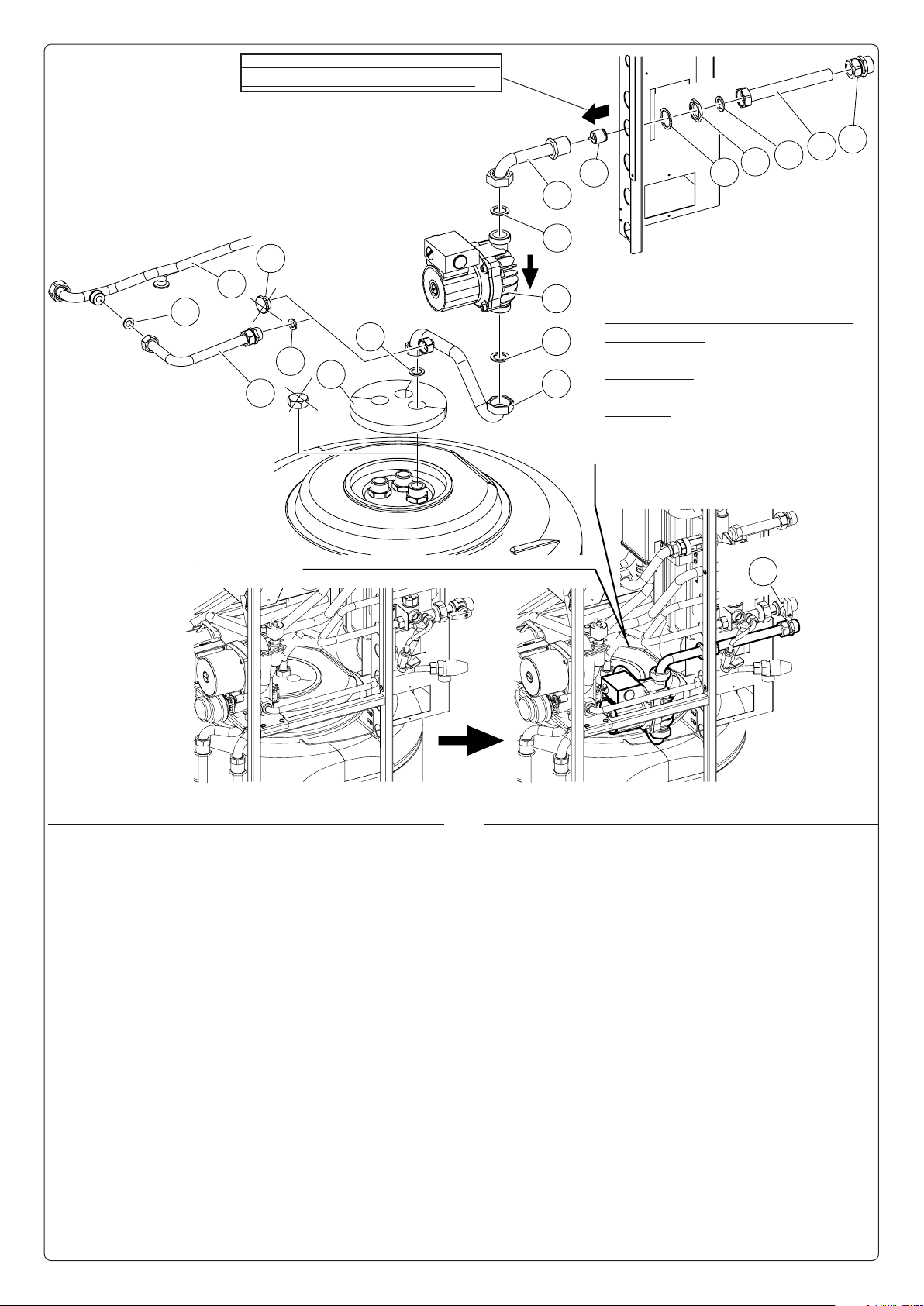
Nel caso di installazione del solo "Kit ricircolo" consultare le
prossime 4 pagine del presente foglio istruzioni.
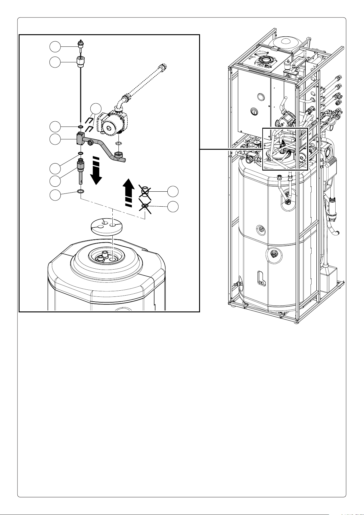
Nel caso di montaggio del "Kit ricircolo" in concomitanza del "Kit
tuboricircoloabbinamentoanodo elettronico"consultareperintero
il presente foglio istruzioni. Ricordarsi inoltre di iniziare l'instal-
lazione dal "Kit tubo ricircolo abbinamento anodo elettronico".
GENERAL WARNINGS.
All products are protected with suitable transport packaging.
e material must be stored in dry environments and protected
against weathering.
is instruction manual provides technical information for installing
the kit. As for the other issues related to kit installation (e.g. safety
in the work site, environment protection, injury prevention), it is
necessary to comply with the provisions specied in the regulations
in force and principles of good practice.
Improper installation or assembly of the appliance and/or compo-
nents, accessories, kit and devices can cause unexpected problems
to people, animals and objects. Read the instructions provided with
the product carefully to ensure a proper installation.
Installation and maintenance must be performed in compliance with
the regulations in force, according to the manufacturer's instructions
and by authorised professionally qualied sta, intending sta with
specic technical skills in the plant sector, as envisioned by the Law.
If only the “Recirculation kit” is installed, consult the next 4
pages of this instruction manual.
If the “Recirculation kit” is installed together with the “Electronic
anode coupling recirculation pipe kit”, consult this instruction
manual in full. Remember also to start the installation from the
“Electronic anode coupling recirculation pipe kit”.

RECIRCULATION KIT INSTALLATION
Hercules kW and Hercules condensing kW (Fig. 1).
It is recommended to lubricate the O-Ring connections with
common liquid soap slightly diluted with water.
Cut power to the appliance by disconnecting the switch upstream
from the boiler.
Remove the boiler casing.
Preparing the system
Make sure that the cold water inlet tap (12) is closed and lower
the pressure inside the storage tank / cylinder by momentarily
opening the drain valve.
Facilitate this operation by opening any hot water tap of the domestic
hot water system to let air into the storage tank.
Installation
Temporarily remove the upper insulation (1) and the cap on the
storage tank.
Connect the kit as shown in the gure.
N.B.: pay attention to the connection of the pump whose water
circulation direction must be the same as the arrow shown in the
gure, as well as the OV20 one-way valve / non-return valve (7).
Once assembly is complete, cover the storage tank connections
with the previously removed insulation (1).
e power supply cable must be connected to a 230V ±10% / 50Hz
mains supply observing L-N polarity and earth connection; this
network must also feature an omnipolar circuit breaker of class
III overvoltage category.
Make sure to have closed the storage tank draining valve. Close the
previously opened DHW (Domestic hot water) system hot water
tap. Reopen the cold water inlet valve (12), remount the casing,
then power the boiler to bring it to normal operating conditions.
INSTALLAZIONE KIT RICIRCOLO
Hercules kW e Hercules condensing kW (Fig. 1).
Si suggerisce di lubricare tutte le connessioni O-Ring tramite
comune sapone liquido diluito leggermente con acqua.
Togliere tensione all'apparecchio disalimentando l'interruttore a
monte della caldaia.
Smontare la mantellatura della caldaia.
Preparazione impianto
Accertarsi che il rubinetto ingresso acqua fredda (12) sia chiuso
e abbassare la pressione all'interno del bollitore aprendo momen-
taneamente il rubinetto di svuotamento.
Agevolare l'operazione aprendo un qualsiasi rubinetto dell’acqua calda
dell’impianto sanitario per permettere l’entrata dell’aria nel boiler.
Installazione
Asportare momentaneamente la coibentazione superiore (1) ed
eliminare il tappo presente sul bollitore.
Eettuare il collegamento del kit come rappresentato in gura.
N.B.: prestare attenzione al collegamento della pompa che deve
avere il senso di circolazione dell'acqua uguale alla freccia rap-
presentata in gura così come la valvola unidirezionale OV20(7).
Ultimato il montaggio coprire gli allacciamenti del bollitore con
la coibentazione (1) precedentemente asportata.
Allacciare il circolatore ad una rete di 230V ±10% / 50Hz rispet-
tando la polarità L-N ed il collegamento di terra, su tale rete deve
essere prevista una disconnessione onnipolare con categoria di
sovratensione di classe III.
Accertarsi di aver chiuso il rubinetto di svuotamento boiler.
Chiudere il rubinetto dell’acqua calda dell’impianto sanitario
precedentemente aperto. Riaprire il rubinetto entrata acqua fredda
(12), rimontare la mantellatura, quindi ridare tensione alla caldaia
per portarla alle normali condizioni di funzionamento.

4
1
2
4
8
12
9210
3
5
6
11
7
Composizione kit:
n° 2-Guarnizione piana 24x16x2 mm (2)
n° 1-Tubo allacciamento ricircolo (3)
n° 2-Guarnizione piana 29x20x2 mm (4)
n° 1-Circolatore (5)
n° 2-Curve circolatore (da scegliere in funzione del proprio mo-
dello di caldaia (6)
n° 1-Valvola unidirezionale OV20 (7)
n° 1-Guarnizione piana 34x27x2 mm (8)
n° 1-Dado ribassato (9)
n° 1-Tubo allacciamento (10)
n° 1-Raccordo tubo allacciamento 3/4'' (10)
n° 2-Guarnizione piana 18,5x11,5x2 (13)
n° 1-Tubo con valvola di non ritorno OV 15 (14)
Legenda:
1 -Coibentazione bollitore
12 -Rubinetto entrata acqua fredda
15 -Tubo presente in caldaia
Fig. 1
ATTENZIONE:
questo circolatore è indicato solo per l'acqua potabile
ATTENTION:
this circulator is indicated for drinking water only
Nel caso di montaggio dell'anodo elettronico, utilizzare
il kit 3.030689 e fare riferimento alla g. 3
If the electronic anode is installed, use the 3.030689
kit and refer to g.3
DIREZIONE MONTAGGIO CORRETTA
DIRECTION ASSEMBLY CORRECT
Kit composition:
n° 2-24x16x2 mm Flat gasket / seal (2)
n° 1-Recirculation connection pipe (3)
n° 2-29x20x2 mm Flat gasket / seal (4)
n° 1-Circulator (5)
n° 2-Circulator curves (to be chosen according to your boiler
model (6)
n° 1-OV20 One-way valve / non-return valve (7)
n° 1-34x27x2 mm Flat gasket / seal (8)
n° 1-Lowered nut (9)
n° 1-Connection pipe (10)
n° 1-Connection pipe tting 3/4'' (10)
n° 2-18.5x11.5x2 Flat gasket / seal (13)
n° 1-Pipe with OV 15 non-return valve (14)
Key:
1 -Storage tank / cylinder insulation
12 -Cold water inlet tap
15 -Pipe present in boiler

Hercules solar 200 condensing (Fig. 2).
It is recommended to lubricate the O-Ring connections with
common liquid soap slightly diluted with water.
Cut power to the appliance by disconnecting the switch upstream
from the boiler.
Remove the boiler casing.
Preparing the system
Make sure that the cold water inlet tap (12) is closed and lower
the pressure inside the storage tank / cylinder by momentarily
opening the drain valve.
Facilitate this operation byopening any hot water tap of the domestic
hot water system to let air into the storage tank.
Installation
Temporarily remove the upper insulation (1) and the cap on the
storage tank.
Remove the cap (16) from the pipe (3).
Connect the kit as shown in the gure.
N.B.: pay attention to the connection of the pump whose water
circulation direction must be the same as the arrow shown in the
gure, as well as the OV20 one-way valve / non-return valve (7).
Once assembly is complete, cover the storage tank connections
with the previously removed insulation (1).
e power supply cable must be connected to a 230V ±10% / 50Hz
mains supply observing L-N polarity and earth connection; this
network must also feature an omnipolar circuit breaker of class III
overvoltage category.
Make sure to have closed the storage tank draining valve. Close the
previously opened DHW (Domestic hot water) system hot water
tap. Reopen the cold water inlet valve (12), remount the casing,
then power the boiler to bring it to normal operating conditions.
TECHNICAL DATA:
- Electric power supply: 230 Vac / 50 HZ
- Power: ............................................. 55 W
- Absorption: ...................................0.24 A
Hercules solar 200 condensing (Fig. 2).
Si suggerisce di lubricare tutte le connessioni O-Ring tramite
comune sapone liquido diluito leggermente con acqua.
Togliere tensione all'apparecchio disalimentando l'interruttore a
monte della caldaia.
Smontare la mantellatura della caldaia.
Preparazione impianto
Accertarsi che il rubinetto ingresso acqua fredda (12) sia chiuso
e abbassare la pressione all'interno del bollitore aprendo momen-
taneamente il rubinetto di svuotamento.
Agevolare l'operazione aprendo un qualsiasi rubinetto dell’acqua
calda dell’impianto sanitario per permettere l’entrata dell’aria nel
boiler.
Installazione
Asportare momentaneamente la coibentazione superiore (1) ed
eliminare il tappo presente sul bollitore.
Eliminare il tappo (16) presente sul tubo (3).
Eettuare il collegamento del kit come rappresentato in gura.
N.B.: prestare attenzione al collegamento della pompa che deve
avere il senso di circolazione dell'acqua uguale alla freccia rap-
presentata in gura così come la valvola unidirezionale OV20(7).
Ultimato il montaggio coprire gli allacciamenti del bollitore con
la coibentazione (1) precedentemente asportata.
Allacciare il circolatore ad una rete di 230V ±10% / 50Hz rispet-
tando la polarità L-N ed il collegamento di terra, su tale rete deve
essere prevista una disconnessione onnipolare con categoria di
sovratensione di classe III.
Accertarsi di aver chiuso il rubinetto di svuotamento boiler.
Chiudere il rubinetto dell’acqua calda dell’impianto sanitario
precedentemente aperto. Riaprire il rubinetto entrata acqua fredda
(12), rimontare la mantellatura, quindi ridare tensione alla caldaia
per portarla alle normali condizioni di funzionamento.
DATI TECNICI:
- Alimentazione elettrica: 230 Vac / 50 HZ
- Potenza: .......................................... 55 W
- Assorbimento: ..............................0,24 A
A = Prevalenza disponibile al circolatore terza velocità
B = Prevalenza disponibile al circolatore seconda velocità
C = Prevalenza disponibile al circolatore prima velocità
Prevalenza circolatore
Prevalenza (m c.a.)
Head (m c.a.)
Portata (l/h)
Flow rate (l/h)
Prevalenza (kPa)
Head (kPa)
A
B
C
Circulator head
A = Head available to the third speed circulator
B = Head available to the second speed circulator
C = Head available to the rst speed circulator

15
4
1
2
4
8
12
9210
3
5
6
11
14
13
13
7
16
Fig. 2
Kit composition:
n° 2-24x16x2 mm Flat gasket / seal (2)
n° 1-Recirculation connection pipe (3)
n° 2-29x20x2 mam Flat gasket / seal (4)
n° 1-Circulator (5)
n° 2-Circulator curves (to be chosen according to your boiler
model (6)
n° 1-OV20 One-way valve / non-return valve (7)
n° 1-34x27x2 mm Flat gasket / seal (8)
n° 1-Lowered nut (9)
n° 1-Connection pipe (10)
n° 1-Connection pipe tting 3/4'' (11)
n° 2-18.5x11.5x2 Flat gasket / seal (13)
n° 1-Pipe with OV 15 non-return valve (14)
Key:
1 -Storage tank / cylinder insulation
12 -Cold water inlet tap
15 -Pipe present in boiler
16 -Plug G 1/2" F
DIREZIONE MONTAGGIO CORRETTA
DIRECTION ASSEMBLY CORRECT
ATTENZIONE:
questo circolatore è indicato solo per
l'acqua potabile
ATTENTION:
this circulator is indicated for drinking
water only
If the electronic anode is installed, use the 3.030689 kit and
refer to g. 3
Nel caso di montaggio dell'anodo elettronico, utilizzare il kit
3.030689 e fare riferimento alla g. 3
Composizione kit:
n° 2-Guarnizione piana 24x16x2 mm (2)
n° 1-Tubo allacciamento ricircolo (3)
n° 2-Guarnizione piana 29x20x2 mm (4)
n° 1-Circolatore (5)
n° 2-Curve circolatore (da scegliere in funzione del proprio
modello di caldaia (6)
n° 1-Valvola unidirezionale OV20 (7)
n° 1-Guarnizione piana 34x27x2 mm (8)
n° 1 - Dado ribassato (9)
n° 1-Tubo allacciamento (10)
n° 1-Raccordo tubo allacciamento 3/4'' (11)
n°2 -Guarnizione piana 18,5x11,5x2 (13)
n° 1-Tubo con valvola di non ritorno OV 15 (14)
Legenda:
1 -Coibentazione bollitore
12 -Rubinetto entrata acqua fredda
15 -Tubo presente in caldaia
16 -Tappo G 1/2" F

INSTALLAZIONE KIT TUBO RICIRCOLO
ABBINAMENTO ANODO ELETTRONICO
Hercules kW (Fig. 3).
Si suggerisce di lubricare tutte le connessioni O-Ring tramite
comune sapone liquido diluito leggermente con acqua.
Eseguire le operazioni preliminari come indicato nel paragrafo
precedente "Installazione modelli Hercules KW e Hercules Con-
densing KW".
- Eliminare il raccordo (1) e relativo O-Ring (2).
- Premontare l'O-Ring inferiore (4a) e l'O-Ring superiore (4b)
sul raccordo (3).
- Fissare il raccordo premontato (3+4a+4b) al coperchio del bol-
litore serrandolo con apposita chiave esagonale.
- Prendere il tubo ricircolo con massello (5) in dotazione e chiu-
dere la diramazione con girello non utilizzata tramite il tappo
maschio G 1/2" (16) e relativa guarnizione piana (13) montati
sul tubo ricircolo presente nel kit ricircolo cod. 3.020001.
- Inserire il massello del nuovo tubo ricircolo (5), sul raccordo (3)
come indicato in Fig. 3, posizionando sul lato destro il tubo in
rame sagomato assicurandosi che le superci in ottone siano
in battuta.
- Bloccare il raccordo (3+4a+4b) sul massello (5)inserendo la
forcella posteriormente (6) nei fori inferiori.
- Applicare materiali di tenuta quali teon o simili sulla lettatura
dell'anodo (7).
- Premontare l'anodo (7) con teon sul raccordo (8).
N.B.: Non forzare il serraggio del corpo in plastica su quello
in ottone assicurandosi comunque di ottenere la necessaria
tenuta.
- Posizionare l'O-Ring (4b) nell'apposita sede presente sul rac-
cordo (8).
- Inserire il gruppo premontato (7+8+4b) no a battuta sul mas-
sello (5) e bloccarlo inserendo la forcella posteriormente (6)
nei fori superiori.
Per il montaggio del circolatore e dei tubi presenti nel "Kit ri-
circolo" fare riferimento al paragrafo precedente "Installazione
modelli Hercules KW e Hercules Condensing KW" ricordandosi
che il tubo di allacciamento (3) di Fig. 1 non verrà utilizzato.
Per i collegamenti degli anodi fare riferimento al foglio istruzioni
dei kit cod. 3.030694 e cod. 3.029643.
ELECTRONIC ANODE COUPLING RECIRCULATION
PIPE KIT INSTALLATION
Hercules kW (Fig. 3).
It is recommended to lubricate the O-Ring connections with
common liquid soap slightly diluted with water.
Perform the preliminary operations as indicated in the previous
paragraph "Installation of Hercules KW and Hercules Condens-
ing KW MODELS".
- Eliminate the tting (1) and relative O-Ring (2).
- Pre-assemble the lower and upper O-Rings (4a) and (4b) on the
tting (3).
- Fix the pre-assembled tting (3+4a+4b) to the storage tank /
cylinder cover by tightening with appropriate hexagonal key.
- Take the recirculation pipe with block (5) supplied and close
the junction with unused swivel using the male plug G 1/2” (16)
and relative at gasket / seal (13) assembled on the recirculation
pipe present in the recirculation kit code 3.020001.
- Insert the block of the new recirculation pipe (5) on the tting
(3) as shown in Fig. 3, positioning the shaped copper pipe on
the right side, making sure that the brass surfaces are at the end
stop.
- Block the tting (3+4a+4b) on the block (5) by inserting the
rear fork (6) in the lower holes.
- Apply the sealing materials such as the Teon or similar on the
thread of the anode (7).
- Pre-assemble the anode (7) with teon on the tting (8).
N.B.: Do not force the plastic body on the brass body, making
sure to obtain the necessary seal.
- Position the O-Ring (4b) in the appropriate seat on the tting
(8).
- Insert the pre-assembled unit (7+8+4b) to the end stop on the
block (5) and lock it by inserting the rear fork (6) in the upper
holes.
To assemble the pump / circulator and the pipes in the “Recircula-
tion kit”, refer to the previous paragraph “Installation of Hercules
KW and Hercules Condensing KW models”, remembering that
the connection pipe (3) of Fig. 1 will not be used.
For the anode connections, refer to the instruction manual of the
kits code 3.030694 and code 3.029643.

3
1
2
8
4a
4b
4b
5
6
7
16
13
Fig. 3
Kit composition:
1 -Male Nipples 3-4"/3-4" (*)
2 -EPDM O-Ring (*)
3 -Lower tting unit with probe pipe 3/4” M - Quick
coupling M
4a -Cover seal PEROX EPDM O-Ring
4b -Quick coupling seal PEROX EPDM O-Ring
5 -Recirculation pipe with block for anode
6 -Locking fork
7 -Electronic anode
8 -Quick coupling tting M - 1/2" RC L=32
13 -18.5x11.5x2 mm Flat gasket / seal (°)
16 -Plug G 1/2" F (°)
(*) Present on storage tank / cylinder
(°) Present in the recirculation kit 3.020001.
Composizione kit:
1 -Nipples 3-4"/3-4" maschio (*)
2 -O-Ring EPDM (*)
3 -Gruppo raccordo inferiore con tubo sonda 3/4" M - Innesto
rapido M
4a -O-Ring EPDM PEROX tenuta coperchio
4b -O-Ring EPDM PEROX tenuta innesti rapidi
5 -Tubo ricircolo con massello per anodo
6 -Forcella bloccaggio
7 -Anodo elettronico
8 -Raccordo innesto rapido M - 1/2" RC L=32
13 -Guarnizione piana 18,5x11,5x2 mm (°)
16 -Tappo G 1/2" F (°)
(*) Presente sul bollitore
(°) Presente nel kit ricircolo 3.020001.

Hercules solar (Fig. 4).
Si suggerisce di lubricare tutte le connessioni O-Ring tramite
comune sapone liquido diluito leggermente con acqua.
Eseguire le operazioni preliminari come indicato nel paragrafo
precedente "Installazione modello Hercules Solar 200 Conden-
sing".
- Eliminare il raccordo (1) e relativo O-Ring (2).
- Premontare l'O-Ring inferiore (4a) e l'O-Ring superiore (4b)
sul raccordo (3).
- Fissare il raccordo premontato (3+4a+4b) al coperchio del bol-
litore serrandolo con apposita chiave esagonale.
- Inserire il massello del nuovo tubo ricircolo (5), sul raccordo (3)
come indicato in Fig. 4, posizionando sul lato destro il tubo in
rame sagomato assicurandosi che le superci in ottone siano
in battuta.
- Bloccare il raccordo (3+4a+4b) sul massello (5)inserendo la
forcella posteriormente (6) nei fori inferiori.
- Applicare materiali di tenuta quali teon o simili sulla lettatura
dell'anodo (7).
- Premontare l'anodo (7) con teon sul raccordo (8).
N.B.: Non forzare il serraggio del corpo in plastica su quello
in ottone assicurandosi comunque di ottenere la necessaria
tenuta.
- Posizionare l'O-Ring (4b) nell'apposita sede presente sul rac-
cordo (8).
- Inserire il gruppo premontato (7+8+4b) no a battuta sul mas-
sello (5) e bloccarlo inserendo la forcella posteriormente (6)
nei fori superiori.
Per il montaggio del circolatore e dei tubi presenti nel "Kit Ri-
circolo" fare riferimento al paragrafo precedente "Installazione
modello Hercules Solar 200 Condensing"ricordandosi che il tubo
di allacciamento (3) di Fig. 2 non verrà utilizzato.
Per i collegamenti degli anodi fare riferimento al foglio istruzioni
dei kit cod. 3.030694 e cod. 3.029643.
Hercules solar (Fig. 4).
It is recommended to lubricate the O-Ring connections with
common liquid soap slightly diluted with water.
Perform the preliminary operations as indicated in the previous
paragraph "Installation of Hercules Solar 200 Condensing model".
- Eliminate the tting (1) and relative O-Ring (2).
- Pre-assemble the lower and upper O-Rings (4a) and (4b) on the
tting (3).
- Fix the pre-assembled tting (3+4a+4b) to the storage tank /
cylinder cover by tightening with appropriate hexagonal key.
- Insert the block of the new recirculation pipe (5) on the tting
(3) as shown in Fig. 4, positioning the shaped copper pipe on
the right side, making sure that the brass surfaces are at the end
stop.
- Block the tting (3+4a+4b) on the block (5) by inserting the
rear fork (6) in the lower holes.
- Apply the sealing materials such as the Teon or similar on the
thread of the anode (7).
- Pre-assemble the anode (7) with teon on the tting (8).
N.B.: Do not force the plastic body on the brass body, making
sure to obtain the necessary seal.
- Position the O-Ring (4b) in the appropriate seat on the tting
(8).
- Insert the pre-assembled unit (7+8+4b) to the end stop on the
block (5) and lock it by inserting the rear fork (6) in the upper
holes.
To assemble the pump / circulator and the pipes in the “Recircula-
tion Kit”, refer to the previous paragraph “Installation of Hercules
Solar 200 Condensing model”, remembering that the connection
pipe (3) of Fig. 2 will not be used.
For the anode connections, refer to the instruction manual of the
kits code 3.030694 and code 3.029643.

3
1
2
8
4a
4b
4b
5
6
7
Fig. 4
Kit composition:
1 -Male Nipples 3-4"/3-4" (*)
2 -EPDM O-Ring (*)
3 -Lower tting unit with probe pipe 3/4” M - Quick
coupling M
4a -Cover seal PEROX EPDM O-Ring
4b -Quick coupling seal PEROX EPDM O-Ring
5 -Recirculation pipe with block for anode
6 -Locking fork
7 -Electronic anode
8 -Quick coupling tting M - 1/2" RC L=32
(*) Present on storage tank / cylinder
Composizione kit:
1 -Nipples 3-4"/3-4" maschio (*)
2 -O-Ring EPDM (*)
3 -Gruppo raccordo inferiore con tubo sonda 3/4" M - Innesto
rapido M
4a -O-Ring EPDM PEROX tenuta coperchio
4b -O-Ring EPDM PEROX tenuta innesti rapidi
5 -Tubo ricircolo con massello per anodo
6 -Forcella bloccaggio
7 -Anodo elettronico
8 -Raccordo innesto rapido M - 1/2" RC L=32
(*) Presente sul bollitore


This manual suits for next models
1
Table of contents
Other Immergas Water System manuals
Popular Water System manuals by other brands

AquaLiv
AquaLiv A500 Usage & installation instructions

AquaSure
AquaSure AS-PR50S owner's manual

Wave Home Solutions
Wave Home Solutions HYDROCARE DUAL ACTION installation manual

Puretec
Puretec ESR2 Series user guide

Pure-Pro
Pure-Pro ASTROBOY user manual

Hitech
Hitech New Life aa++ Installation & operational manual

Aqua Guard
Aqua Guard JAZZ user manual

Waterco
Waterco MULTI CYCLONE 70XL manual

Aqua Guard
Aqua Guard RBS TRITON 35 Operating and maintenance instructions

Baxi
Baxi UBVT 200 DC Installation, user and service manual

Kingspan
Kingspan Varisol installation manual

Solar Energy
Solar Energy WWKS Installation and operating manual