UPRENT BBA PT 250 Series User manual

www.uprent.eu
PUMPING AND ENERGY SOLUTIONS
PUMP
USER
MANUAL

Electric piston pump on the frame
Technical specification:
Intended use To lower the groundwater level
Make / Type BBA / PT250
Maximal flow 190 m3 / h
Maximal head 20 mwc
Maximal suction lift 9,5m
Suction connection 2 x 6’’
Discharge connection 2 x 6’’
Dimensions L x W x H 2550mm x 1040mm x 1480mm
Weight 1840kg
Engine Electric motor
Engine type HMC2 160L –4
Engine power / rpm 15 kW / 1480 rpm
Voltage / Phase / Frequency 400V / 3 phase / 50Hz
Rated current 28 A
Connection socket 32A with phase change
GPS Equipped with GPS

1
User Manual
PT250 series Electro

2
Contents
1
Description, application and working principle........................................................3
1.1 Description............................................................................................................3
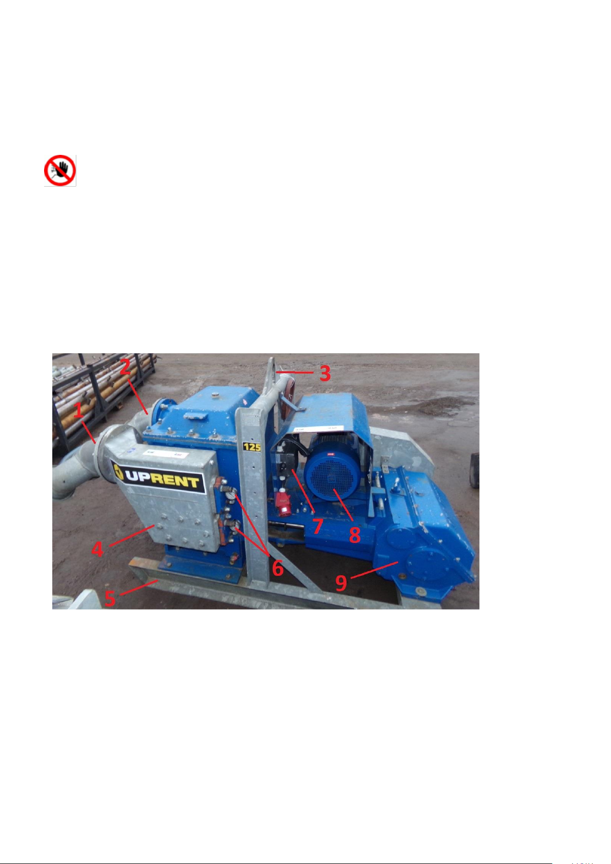
1.2 Construction of the pump unit............................................................................3
1.3 Intended use .........................................................................................................4
1.4 Unintended use.....................................................................................................4
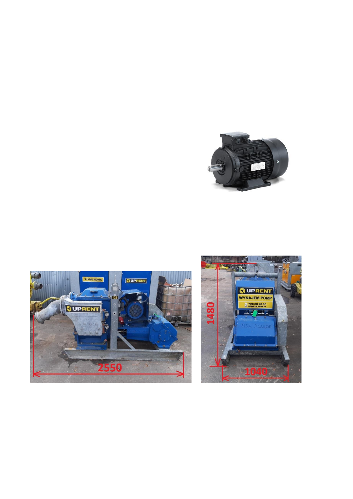
1.5 specification and dimensions .............................................................................4
2
Safety instruction........................................................................................................6
2.1 Warning stickers...................................................................................................6
3
Lifting instructions PT250 pump unit........................................................................8
4
Pump unit installation...............................................................................................10
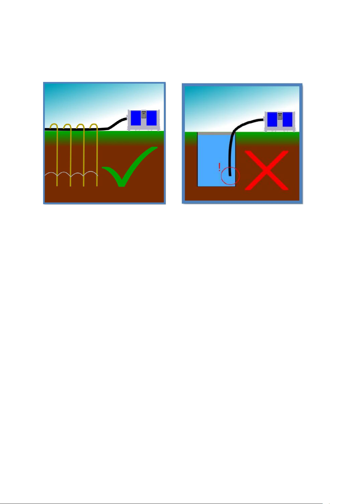
4.1 Placement –general...........................................................................................10
5
Pump –general .........................................................................................................11
5.1 Preparation for starting the pump unit.............................................................11
5.2 To fill the pump housing with water:................................................................11
5.3 Control panel ......................................................................................................11
5.4 Checking the direction of rotation....................................................................12
6
Daily maintenance of the pump ...............................................................................13
7
Preperation for starting............................................................................................14
8
Starting and stopping...............................................................................................15
9
Regulating vacuum on suction line.........................................................................17
10
Monitoring during operation....................................................................................18
11
Draining the pump when there is danger of freezing.............................................19
12
Troubleshooting table ..............................................................................................20

3
1
Description, application and working principle
1.1 Description
WARNING: This manual is intended to give Important Information that must be followed
during Storage, Transportation, Installation, Operation and Maintenance of the Pump-Set.
We therefore recommend that this manual is read carefully before the Pump-Set is put into
operation. To prevent damage being caused by inappropriate or incorrect use, or by being
used outside the normal operating parameters of the Pump-set, the Instructions in this
manual must be followed. Failure to do so may lead to damage to or premature failure of the
Pump-set and may cause Injury. Any such actions will invalidate the warranty.
The PT series piston pumps have been designed for vertical and horizontal dewatering applications.
These high efficiency positive displacement pumps are self-priming and suitable for pumping a mix of
water andair under anyconditions.Furthermore, these pumpscanrun drywithout damage orexcessive
wear to any part of the unit. The data sheet that accompanies the pump includes all data for the pump
unit. Before the pump unit is connected, an assessment must always be made to determine whether it
is suitable for the intended application.
1.2 Construction of the pump unit
1.
Suction side
2.
Pressure side
3.
Lifting eye
4.
Stone cather
5.
Frame
6.
Vacuum gauges
7.
Control box
8.
Motor
9.
Pump drive side

4
1.3 Intended use
The PT series piston pump is only intended for pumping water from filters or drainage
hose(s),NOT for pumping dirty water drawn directly from the suction hose, with or without a strainer.
Long fibres will cause immediate malfunctions. The maximum permissible particle size is 5 mm.
Contamination results in accelerated wear of the gland packing, gaskets, valve seals, cylinder sleeves
and piston cups.
ThePT series piston pumps are suitable for pH-neutral water (pH value 7) at a maximum temperature of
30°C (86°F) and not for chemically polluted water or water with a pH value higher than 7.
1.4 Unintended use
−
It is not permitted to use the pump unit for pumping salt water.
−
It is not permitted to use the pump unit for pumping liquids containing larger suspendedsolids.
−
It is not permitted to use the pump unit for pumping flammable and/or explosive substances.
−
Itis notpermitted todeployastandard pump unitinan environment in which there is adanger of fire
and/or explosion.
−
It is not permitted to deploy a standard pump unit in an ATEX environment.
−
Use the pump unit only for those applications listed on the specification sheet for the pumpunit.
−
It is not permitted to use the pump unit for any application and/or field of activity other than that for
which the pump unit was originally specified and installed without written permission from BBA
Pumps.
1.5 specification and dimensions
Pump specifications:
Type ........................ PT250E
Design.....................Double acting, duplex piston pump
Max. flow ................ 190 m3/hour
Max. pressure ......... 20 mwc
Max. suction lift ....... 9.6 mwc
Connections ............ 2 x 6"

5
Electric motor .......... 15 kW (20Hp)
Voltage ................... 400/690V –50Hz
Weight (net) ............ 1840 kg
Speed (factory standard) ..... 62 strokes/min
Pump casing ........................ St.37
Cylinder liners ...................... Stainless steel 1.4301
Piston cups .......................... Leather
Piston rods ........................... Stainless steel 304
Shaft seal ............................. Gland packing
Valve rubbers....................... NBR
Measure equipment ............. 2 vacuum gauges
Electric motor
Motor type ............................ HMA2
Power ................................... 15 kW (20 Hp)
Speed .................................. 1480 RPM
Voltage ................................. 400/690 V
Frequency ............................ 50 Hz
Poles .................................... 4
Protection ............................. IP55
Efficiency ............................. IE2
Star-delta ............................. Manual
Plug ...................................... 5 pin - 32 Amp.
BBA stackable frame
Frame SF10-21 ................... Steel hot dip galvanised
Dimensions L x W x H ......... 2550 x 1040 x 1480 mm
Lifting point .......................... Fitted with single lifting point
Motor rain cover ................... Steel hot dip galvanised

6
2
Safety instruction
This manual contains warning and safety symbols. Do not ignore the instructions. They are provided
for the benefit of your health and safety and to prevent damage to the environment and the pump unit.
DANGER
When the danger symbol with the text DANGER is shown, it is accompanied by
information that is of great importance for the safety of everyoneconcerned.
Ignoring the information can result in injury (possibly severe) or evendeath.
WARNING
When the warning symbol with the text WARNING is shown, it is accompanied
by information that is of great importance for everyone concerned with the pump
unit. Ignoring the information can result in injury or damage (possibly severe) to
the pump
unit.
The pump unit conforms to the European Machinery Directive. However, this does not exclude the
possibility of accidents if used incorrectly.
Useof the pump for an application and/or deployment of thepump in anenvironment other than defined
at the time of purchase is strictly prohibited and can result in a hazardous situation.
This is particularly true for corrosive, toxic or other hazardous liquids. The pump unit may only be
installed, operated and maintained by persons who have received appropriate training and are aware
of the associated dangers.
The installer, operator and maintenance personnel must comply with the local safety regulations. The
company management is responsible for ensuring that all work is performed by qualified personnel in
a safe manner. It is not permitted to make changes to the pump unit without written permission from
BBA Pumps.
If any changes are made to the pump without the written permission of BBA Pumps, BBA Pumps
disclaims all liability. Hearing protection must be worn if the noise emission level exceeds 85 dB(A).
Ensure that hot/cold and rotating parts of the pump are shielded adequately to prevent unintentional
contact.
It is not permitted to start the pump if such guards are missing or damaged.
The company management must ensure that everyone who works with/on the pump unit is aware of the
type of liquid that is being pumped. These persons must know what measures are to be taken in the
event of leakage.
Dispose of any liquids that have leaked, in a responsible manner. Observe local regulations
Never allow the pump unit to run with a blocked discharge line. The heat build-up could lead to an
explosion
2.1 Warning stickers
Warning stickers are applied to the pump unit as applicable to the specific version. Make sure these
symbols are and remain clearly legible
A
Label for the transport of hazardous materials (hazardous goods) in accordance withthe
safety standard for the transport of hazardous goods.
TheUN 1202 class 3 placard indicates the presence of gas oil, diesel fuel or light heating
oil.

7
B
Diesel is hazardous to the environment, with substantial remediation costs if it leaks into
a drain, waterway or the ground.
C
Caution: hot surface
D
Caution: crushing danger
E
Oil
F
Hazardous or irritating substances
G
General hazard
H
Danger: high voltage
I
Danger: magnetic field
J
Wear hearing protection
K
Instructions for use
L
Dispose of in an environmentally responsible manner at the end of the product's useful
life.

8
3
Lifting instructions PT250 pump unit
DANGER
Never walk under a raised load. This can result in a life-threatening situation.
WARNING
Always disconnect all external connections before moving the pump unit.
WARNING
Neither the lifting eye on the engine nor the lifting eye of the (bare shaft) pump may
be used for transport of the pump unit.
WARNING
Lifting forces must be as vertical as possible; the maximum lifting angle is 15°.
Pump unit in enclosure
There is a lifting eye located on the top of the enclosure. Only lift the unit from this lifting eye.
WARNING
If the pump unit is installed on a swampy or muddy surface, the installation
may be ‘stuck’ to the ground.
DANGER
NEVER move or lift the pump unit by the angle profiles on top of the enclosure or
stacking frame.

9
DANGER
The standard lifting eyes on BBA pump units, both in low-noise enclosure and open
frame, are NOT designed to lift the additional weight of trailers or other components.
It is strictly forbidden to use the standard lifting provision to lift or move the pump
units with a higher total weight than stated in the specification sheets. This can result
in a life-threatening situation.

10
4
Pump unit installation
4.1 Placement –general
WARNING
Failure to follow the guidelines for the placement and installation of the pump can
result in danger to the user and/or severe damage to the pump unit.
Note
BBA Pumps is not responsible for accidents and damage that result from failure to follow the
guidelines in this manual. Such use results in forfeiture of the right to assert any warranty or
damage compensation claims.
−
Place the pump unit on a flat surface capable of supporting the load.
−
Make sure there is sufficient space around the pump unit for operation and maintenanceactivities.

11
5
Pump –general
5.1 Preparation for starting the pump unit
The PT series pumps are self-priming piston pumps with leather piston cups. When the piston cups are
wet they expand against the cylinder sleeve so that the pump can build up vacuum. Therefore the pump
housing must be filled with water.
5.2 To fill the pump housing with water:
1.
Remove the upper cover (1) from the stone catcher.
2.
Fill the stone catcher with water.
3.
Close the cover.
5.3 Control panel
−
PT250 pump is supplied with a star-delta switch(4). Switch has three positions: Neutral (1), Star (2)
and Delta (3).
−
Connection socket 32A (5)

12
5.4 Checking the direction of rotation
WARNING
This test may only be performed by authorised personnel with the appropriate
training.
Check whether the direction of rotation of the motor matches that of the pump.
To check the direction of rotation the motor must be switched on briefly. The motor must not be allowed
to reach the normal operating speed.
If the direction of rotation is incorrect, the connection on the terminal board must be changed or, if a
phase reversal plug is present, the pins of the plug must be reversed.

13
6
Daily maintenance of the pump
−
Check the oil level of the pump.
Note
If the oil in the pump drive has become whitish in colour, replace the oil. The whitish colour may
indicate the presence of excessive condensation water in the oil.
−
Check for possible leaks in the oil and fuelhoses.
−
Check the dripping of the gland packing on
the piston rod; this should not exceed one
drop every five seconds. It may be necessary
to readjust the gland packing at greater lift
heights.
−
Check that the dripping water can drain away from the gland packing. The channel must notbe
plugged on the outside by dirt and sand that have splashed onto the enclosure.
−
Check whether the machine is still placed properly on the ground on which it stands, in accordance
with the instructions. This is important, because the situationcan change as aresult of a build-upof
sand/soil around the pump unit.
−
Check the vacuum above and below the filter in the stone catcher using the two vacuum
gauges on the stone catcher. A difference between the two readings indicates restriction of
the filter, in which case it must be cleaned.
−
Clean stone catcher in following steps
1. Open top cover of stone catcher unscrewing two 24mm nuts, carefully take off cower (1).
2. Look inside, if dirty clean out all obstacles.
3. Place back cover and tighten it up.

14
7
Preperation for starting
1.
Take any necessary measures to ensure that the electrical connections and cables cannotbe damaged
2.
The voltage and frequency must be checked in advance and must match the motor specifications. This
data is shown on the type plate of the motor.
3.
Use of the motor without an overload protection switch is not permitted
4.
Check whether the motor connection matches the mains voltage. See the type plate for the motor. Check
the connections in the terminal box behind the control panel
5.
Check the direction of rotation of the pump
6.
Check the oil level in the drive unit (1).

15
8
Starting and stopping
1. To start the pump, make shore main switch is on “0” position (1) the switch must first be turned to
the star (2) position, and then turned to the delta (3) position within one second.
2. switch must first be turned to the star (2) position for about 1 second.
3. And then turned to the delta (3) position within one second.
WARNING
Turning theswitch too slowlywillcause themotor's thermal protection totrip.Return the
switch to the neutral position and switch it on again.

16
Stopping
To stop the motor, the switch must first be turned from Delta (3) position to the star (2) position,
and then turned to the neutral position (1) within one second.
−
When you suspect that the liquid is beginning to freeze, drain the pump while the medium is still in the
liquid state.

17
9
Regulating vacuum on suction line
If it is necessary to reduce the vacuum on the header pipe somewhat, this can be accomplished by slightly
readjusting the blow valve (1) on the pump. This results in a bit of air leakage developing in the pump at the stone
catcher, which will slightly reduce the total vacuum on the header pipe.
Unscrewing the nipple increases the bleed air from the vacuum regulator valve.

18
10
Monitoring during operation
1. During operation check the pump regularly for correct functioning, smooth and vibration-free running
abnormal noises and leaks.
2. If the pump has pumped for a long time without having moved water, the pump housing must be filled with
water, because the cups shrink after having run dry for a long time. Once the pump housing is filled with
water, the cups will slowly swell again so they are in contact with the cylinder.
3. Check whether the gland packing is leaking; it must be adjusted so one drop of water drips every five
seconds. Loosen the gland packing a bit if it drips more slowly and tighten it a bit if it drips more quickly.
4. The maximum permissible ambient temperature is 40 °C. The temperature of the bearings may not exceed
110 °C.
Note Use for higher temperatures is only permitted after consultation with the supplier.
WARNING
In the event of a problem or incorrect functioning, stop the pump. Determine and
correct the cause before restarting the pump.
This manual suits for next models
1
Table of contents
Other UPRENT Water Pump manuals
Popular Water Pump manuals by other brands

Grizzly
Grizzly TSP 1100 inox Translation of the original instructions for use

mbp
mbp TEL 15-2K-I Series Instructions and parts list

ITT
ITT Goulds Pumps EZMAG 3296 Installation, operation and maintenance instructions

BUSCH
BUSCH COBRA NC 0100 300 B Series Supplement of Installation and Maintenance Instructions

Etatron
Etatron DLX-MF/M Operating instructions and maintenance guide

Sandpiper
Sandpiper s05 Service & operating manual