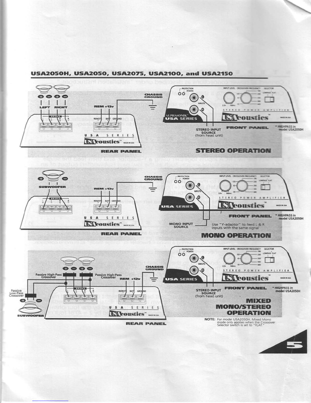
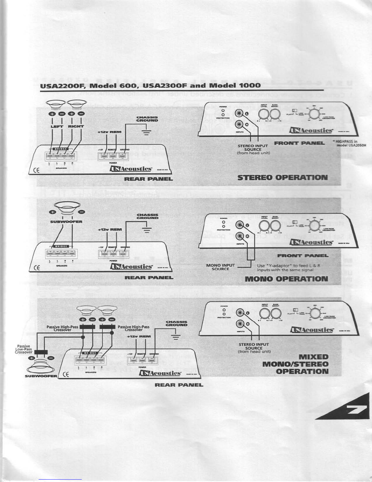
US Acoustics USA2050 User manual

IUI('SFET P('I'VER A]VIPLIFTERS

ttrongratrrlations
on your selectionof this US Acoustics
USA Series
Amplifier.
We take pride in
manufacturingour products,
and you can
expect you
r new amplifier to give you
years
of trouble-freeservice.
To make your installation as easy and
reliable as possible, please read this
manual carefully before beginning. lf
you need more information, your
US
Acoustics
Dealer
will be glad to help.
TMr
JTCT
!,/trt
2424
Blanding
Avenue,Alameda
CA94501
. (510)
864-7005
r FAX
(510)
8*1478

Ounnel's lU|anual
C(DluTEIUTS
nnce @Features
Specifications
Installation/Setti
ng Level
Controls USA2oltoal.U6rrtE{6dtilt5
USA2-Channel
Am lifier
Operation
I USA2-Channel
Amplifier
Operation USAZIOO.I SAIE
USA2:ffi.HCF
USA23Oforun
e USA4o5o
Operation
U544060 Operation
usA4080 0ration
@
@
@usA6300
0ration
Ca
ution
F E AT U R E S
@. Full MOSFET
power supply employing
40 amp high-current
switchfng
deviced -
. 5Onanosecond high-speed diodes
o Latch type protection circuit: in the
event
of a fault condition(either
a short
circuit
on the speaker
terminals,
or DC
on
the speaker
terminals),
this
protection
circuit
willshut
down the amplifiei.
The
amplifier
mustthen be reset
for'continued operation.
. Thermal protection circuitry snutsciown
the amplifier
when it reaches
d5" C,and
aut_ornatica
Ily resets
when temperatu
red
rops
to 75"C. -
. Reverse polarity protection
@. Full MOSFET
design, utilrznng
high
current MOSFETS
in a-ll
outpurt
*ag*
. Variable Low Pass12 dB/ocJave
crossover in stereoamplifiers
(High
Pass
in model
USA2O5OH)
. Variable High and Low Pass
12 dB/octave-crossovent in 4 channel
amplifiers
oThump-free turn on and turn off
. Double differential input circuits
for improved
sound
quality

s
tu
o
T
A
C
F
C
E
P
s
OUTPUT
POWER
Perchannel@4Ohms
@
12.9vinput
Perchannel@2Ohms
@
12.9v
input
BridgedMono@4Ohms
@
12.9v
input
@@@@@@E@@@@
5orrrtx2cH
sIwx:CH 75WnCH
100Wx2CH
,'l50Wx2CH
200Wx2CH
, 300WxXH
50Wx4CH
' 300Wx2CH
80V,fi2CH
80V1,ttH 'l201rVx2CH
150Wx2CH250Wx2CH
300Wx2CH
. {OOW{CH
80Wx4CH
. 400Wx2CH
800\
/x1CH
160Wx2CH
SmWxlCH
160V'fi1CH
160Wx1CH
240V1hlCH
300WxiCH500Wx1CH
600Wx1CH
TOTAL
HARMONIC
DISTORTION U55THAN0.01%
.... .... . ......... o
' o
NOISE
below
rated
outpul , lms 1m
dB 102
dB 104dB 107
dB 109
dB 109dB 104d8 110d8
SLEW
RATE 2CrofVmtcOseCOnd
r r r. . o
. . . ......... ' '
PHASERESPONSE uggrng12hgreaat20kHz
... o........ " o'
INPUTSENSITIVITY ]ffimV-2.ZVOh
.... o. oo. oo.... 100mV-8v
I 100mV'8v
100mV'22v
100mV'8v
INPUT
IMPEDANCE 56KilO0hm
........ o
o....... 17KiloOhm 17KiloOhm56
KiloOhm 17Kilo:Ohm
DAMPING
FACTOR Grgatgr
than
100
. . . . . . . . . o. . . . . . . . ' o' '
Yes , Yes
Yes Yes
Ig'r Y,,s
Yes Yes
Yes
Yes
Yes
Yes
Yes
Yes
Yes
Yes
Yes
Yes
Yes
Yes
Yes
Yes
Yes
Yes
Ys
Ys
Ys
Ys
YS
Yes
Yes
Yes
\B
\a
Its
\b
PROTECTION
Reverse
Polarity
Thermal
Short
Circuit
D.C
IDLECURRENT 0.14 0.4A t.5A
06A
1.0A
1.0A
0.6A
0.4A 0.9A
604
25A
404
40A
35A
35A
ts
l0A
t0A
FUSE
RATING
SIZE Length
width
inches
(mm) Height
11.4i290i
15.7(4S)
63
(160) 6.3
(1S)
1.9
(47.3) r.s
{473)
17,7
(450)
11.4
090) ,,
'19,7
(500)
8.2(2oe)
63(160) 8.2CI0e)
r.g
(47.3) 1.9
(47
3) 1.9
(47.3)
6s(16)
63{t60}
t3{473}
65
i165)
6.3{160i
r.g
(47.3)
7.9pm)
il(tm)
1.e07.3)
17.7
(450)
8
2
009)
1.9
(47.3)
4.0
(l.8) 4.0
(1.8) 4.0i1:8)
,so
(2
27) 8.0
(3.63) 110(s) 11.0{5) 7.0
02) 12.3
(s
0
WEIGHT
lbs.(ks)

lu TA LLAT ots
500Wx2CH
60Wx4CH
700Wx2CH90Wx4CH
1400Wx1tH
180Wx2CH
50Wx4Cfland
50Wx2Cfl
75Wx4CH
and
75Wx2CH
150Wx2CHand
150Wx1CH
CH
5&6ANLY
!00WxlCH
E@I@@t!@@ 1.Locate
a suitable
mountinq location
*c' :-: a*.-
lifier,makingsurethere
is"sufficient'.e-:
-::-
Use
#8-32 screwsto bolt down the a-c -:-
Connecta #8 BLACKwire
to a luo
cc.-i:::' --:
bolt it securelyto the amplifierba"rrie.s:' : -a-i 3:
"GROUND"
and,
using
the shortest
poss:'€ e-l:-
connect it to the chassisof the vehicle
-s -: -
suitablelug.
Connecta#16 wireto a luoand bolt itS,oc-'3nr:: :-.€
amplifier
barrier
stripmarked "
npV "(remole ar': :-€r
connect it to the remoteoutout of the r,e:: -- :
Run
a #8 REDwire from the battervto the e-:i j'e- s
location.Insertthe suppliedfuseholden
c3s€:: :-e
battery, not more than two (2)feet from l-e D.a::e',
Connect
the otherendto a lugconnecto-
a-: 3'3:
itsecurelyto the amplifier
barrierstripmarkec '3rTT'
(+12v).
P/easeNofe:
The
enclosedfuseholdershouldbeconnectedasc/ose:: :-'::.:-.3-,
as
possible.
Althoughthe
manualrecommends#8vn.t :-e*' --
,.,'=
forthefuseholdismorethanadeouateforthe
shoce-Z-#,_
80Wx4CH
120Wx4CH
240Wx2CH
|ESSTHAN0.01%
oo......
110d8 104
dB 105
dB 104d8
20voltVmicrosecond
.. I r...
Ianoinn17Dpnrppsat70kHz . . .
100mV-8v 100mV-8VOlt
.........
17Kilo
Ohm 22KilOOhm
... oo......
Grgaterthanl00
.........
0.7A
6. Connect the speakersystemsto the LEFTar c R,
Gr.T
speakeroutputs,takingcareto observetne co-'ect
phasing
(for
MONO,MIXEDSTEREO/MONO,4
l-:'.'.:*
and Bl-AMP
operation,
seerespective
paragrapFs
- :- :
manualfor speakerhookupdescriptions).
7. Connect a stereo siqnal source to the RCA ac<s
using high-quality sFieldedRCA-RCA patc^ cac es.
SETTITUG LEr'EL C(DIIITROLS
+.
5.
Yes Yes
Yes Yes
Yes Yes
Yes Yes
Ye5
tc)
Ye5
Yes
Yes
Yes
Yx
Ypc
1,0A
U.OA
1.5A
40A25A60A
123(56)
e0(4r) 7e(36) 9,0
{4.
r)
In order to optimize the performance of yor,: scund
system, it isimportant to set the LEVEL
contro s cf
the amplifier(s)correctly.Please
follow this srmce
proceoure:
. Insert
aCDorcassetteintoheadunit.
. SetLEVEL
controlon
theamplifier(s)to MINIMUM
(turn
knob
fully
counterclockwise).
o SetVOLUME
controlon head
unitto about "3 o'cioc<''llf
your headunit uses
"up/down" buttonsfor voirrrrre.
set
the "
up" button to about a5%"of maximumvaiiie
. Now reset
the LEVELcontrolon the amplifierunti tre
required
maximumlisteninglevelisachieved.
1e7(500)r1.4(?90)
c?/?no\ 6?l1f,n\
u.- \LuJt v.J \ |
vw/
1e
(47
3) 1,9
(47
3)
1
1.4
(290)
82
(2oe)
19(47.3)
15,3
090)
8.200e)
r.9
{47,3}

STEREOOPERATIOIU
1.Connectalloower connecttons
asdescribedunder "
lnstallation
Instructions.
"
2.Connect RCA inputsto a siereosignalsourceusing RCA-RCA
patch cables.
3.Connect the speaker
systemsto the speaker
terminals,
observingthe correct
phases.
NOTE: The USA2OSOH, USA2O5O, USA2O75. USAZI(}(), and USA215O may be switched for LOW
PASSOPERATION (USA2Ot5Oll may be switched for HIGHPASS PASSOPERATION):-Slide the
crossover switch to the correct position, and set the crossover control to desired frequency-
ty|OIU(DOPERATI('lu
1 Connect all power connectrons
asdescribedunder "
Installation
Instructions.
"
2.Connect the two RCA inputstogether usinga Y-adaptor,
and then-feed the single
RCA input to a mono signalsource,
suchasthe low pass
(subwoofer)output of an
electronic crossover.
3.Connect the woofer(s)
to the speaker
terminalsas
follows: The positive
connection
of the woofer(s) to thre
lett positive(+) output, and the negative connection of the
woofer(s) to the right negative (-) output.
NOTE: In mono operation, the right positive (+) and left negative (-) speaker terminals have
no connections made to them.
IUI T X E D H (' il O f S T E R E, (o
The USA2O5O, USA2OZ!, USA.ZIOrO, and USAZI5O may be used in mixed mono/stereo mode
(For
USA2O5OH, mixed mono usage
with crossover
in "FLAT" positiononly).
Thismeansthat you may run
satellitespeakers
on the left and rrghtchannelsas in stereooperation, while simultaneously
powering a
mono subwoofer in "bridge
mooe' as
in mono operation.
'1.
Connect all power connections
asdescribedunder "
lnstallation
Instructions.
"
2.The satellitespeakersconnected
to the leflr
and right speaker
terminals
must not have
an impedanceof lessthan four (4)
ohms each,
arid m'ustalso haveappropriatehigh-
pass,passive
crossoversconnected between them and the speaker
terminals.
3.The subwoofer(s)are
then connected asdescribed
in "
MONO OPERATION.
"
4.
The subwoofer(s)total impedance must not be lessthan eight (8)
ohms and must
utilizea low-pass,
passive
crossoverasshown in diagram. Totalspeaker
impedance
presented
to each channel istwo (2)
ohms. Thisis
determined by the tour ohm
satellitein parallel
with half
the subwooferimpedance
(8 divided
bi 2 = 4) of four ohms.
I
i
fr
{
I

USA2OSOH, USA2OSO, USA2O75, USA2.IOO, and USA215O
,r'-----\/----\
\-/\-/
v v
oo@o
ttll
LEFT N]E'IT
ilB&ousties" **^*^
STSRE() INPUT
souRcE
(trom
headunit)
STEREO OPERAITilIT
lnOTUO OPEIUil'TOil
oo@
r@ OUStii['S
FRlC'ff Prtre-
RE'IR P'IilEL
USA SERIES
iFR.o.r.ries' *,^,*
RE/AR PAilEL
o-b
\@
tNMfft (Hrl.F<.'-&- .:-
|F&o,rstics'
FRorr e.E-'Hllillolo5o"
Use"Y-adaptor' tc.eea - & R
inputs with the sa-E s€i-a
€<:
v v
CDOCDO
srEBEo,*"u, FFOF llAlrGt-
souncE
(rrom
headunit) HrrxED
tU|OITIolsTEREO
O]'ERATIOT
r }dGHPASS in
Rodel USA2050H
T moTEctoN
oo@
h@
REF\R PAIUEL

STERE('OPERATI('IU
1.
Connectall
power connections
asdescribed
under "lnstallation
Instructions."
2.
Connect RCA inputs
to a stereo
signalsourceusingRCA-RCA
patch cables.
3.Connect the speakersystems
to the speaker
terminals,observingthe correct
phases.
NOTE: These amplifiers may be switched for HIGHPASS PASSOPERATION: Slide the crossover
switch to the correct position, and set the crossover control to desired frequency.
lulOIUOOPERATIOTU
1 Connect allpower connections
asdescribed
under "
lnstallationInstructions.
"
2.Connect the two RCA inputs
together usinga Y-adaptor,
and then feed the sinqle
RCA input to a mon,osig'nal
sou"rce,such as"the low'pasi (subwoofer) output of an
electronic crossover.
3.Connect the woofer(s)
to the speakerterminals
as
follows: The positive
connection
of the woofer(s) to the left positive(+) output, and the negative connection of the
woofer(s) to the right negative (-) output.
NOTE: In mono operation, the right positive (+) and left negative (-) speaker terminals have
no connections made to them.
MIXEDUOTOfSTEREO
Alphasonik USA22O(DF, Model16100, USA23(X)F and Model1OOO may be used in mixed
mono/stereo mode . Thismeans
that you may run satellitespeakerson the left and right channels
as in
stereooperation,while simultaneously
p6werinj a mono subw6ofer in "bridge mode" aiin mono operation
1.
Connect allpower connections
asdescribed
under "
lnstallationInstructions.
"
1 2.The satellite
speakersconnected
to the left and right speaker
terminalsmust not have
' an impedanceof less
than four (4)
ohms each,and must alsohave
appropriate high-
pass,passive
crossovers
connected between them and the speaker terminals
3.The subwoofer(s)
are
then connected asdescribedin "
MONO OPERATION.
"
4.
The subwoofer(s)
total impedance must not be less
than eight (8)
ohms and must
utilize
a low-pass,
passive
crossover
asshown in diagram. total speakerimpedance
pres.ented
to each channe_lis
two (2) ohms. This isdetermined by the four bhm
satellitein parallel
with half
the subwooferimpedance
(8 dividedbi 2 = 4) of four ohms.

USA22OOE |U|odel 6()(D, USA2SOOF and Model 1OOO
rc fraoo'"rio* --,.
REI\R P'IilEL
STEREO
INPUT
sl)uRcE
(from head unit)
Fl3ilT EIE-
STEREO OPENffrrOil
|nOIUO OPERATIOT
STCNEO
INPUT .
SOUBCE
(from head unit) U]XED
tU|OilO/STEREO
OPERATIOT
r IXHPASSin
Ddd USA205OH
qoo *'-=c-:
A I 4Ett ."rtt"s' ---
FffiTBTE-
Use
'Y-adaetor'toH f&R
inputs with the sarnesrgre
REAR P'TilEL
GG
: v
o€ct(D
PassiveHioh-Pass
Crcssler
|_TTT rug"---
REF\R P'\IIIEL

USAI*O5O 4-C HAIf,EL A]U|PLIFIER
1.Connect all power connectlons
asdescnbedunder "
Installation
Instructions.
"
2.Connect RCA inputsto a steneo
srgnal
sourceusing RCA-RCA
patch cables.
3. Connect the speaker systeri'rs
to the speaker terminals, observing the correct
phases.
Note: Setting the MODE switdr to 'Crossover" position allows the USA4O5O
amp to use dhannels 1 &2 as hkrhpass channeli and Channels 3 & 4 as lowpass
channels. Adiust each frequencf cbntrol to the desired position.
BI.AMPOPERATIOIU
1.Connect all power connecttons
asdescribed
under "
lnstallation
Instructions.
"
2.Connect the RCA inputs 1 & 3 together usinga Y-adaptor.
Connect the RCA
inputs 2 &4 together using a Y-adaptor.Then feed these RCA inputsto a
stereosignalsource.
3.SetMODE switch to 'Crossover' position.
tU|IXEDTOTOft5TEREO
USA-seriesamplifier USA4TO!5O
may be used in mixed mono/stereo mode. Thismeans
thatyou mayrunsatellitespeakers
on ihe left
and rightchannels
as
instereo
operation,
while
simuftaneou-sly
powering
a mono
subwoofer
in "bridge
mode" as
inmono
operation.
1.Connectall
power connectrons
asdescribed
under "lnstallation
Instructions."
2.The satellitespeakers
connected to the left and right speaker
terminalsmust not
have
an impebanceof less
than four (4)
ohms each,
and must also
have
appropriate
high-pass,
irassive
crossovers
connected between them and the speaker
terminals.
3.
The subwoofer(s)
arethen connected asdescribed
in "
MONO OPERATION.
"
4.
The subwoofer(s)
total impedance must not be less
than eight (8)
ohms and must
utilizea low-pass,
passive
crossover
asshown in diagram.Totalspeaker
impedance
presented
to each channel istwo (2)
ohms. Thisisdetermined by the loqr-ohm.
Satellite
in parallel
with halfthe subwoofer
impedance
(8 divided
by2 = 4)of four ohms.

usA4('5('
UsA SERIES
B&ousties- -*^,*
gg
oo €o
ct|rtls!5t5
icn(tartD
RAAR F'TffEL
4.CHAIIIIUEL OPERATIOT
BI'AIU|P OPERATIOil
from FRONT and
REAR OUTPUTS Of
I{EAD UNIT
r froTEOoNI I
I -MWER - INffi
"l*@
@-?^^O ILI
I.
I *.-
from STEREo OUTPUTS
of HEAD UNIT
::--:s cH3'oj--l B&ousties'" *,,-,*

USA4OSO 4.(cHAIilEL ArU|PLIFTER
1.
Connect all power connections
asdescribed
under "
lnstallation
Instructions.
"
2.Connect RCA inputsto a stereosrgnal
source
using RCA-RCA
patch cables.
3.Connect the speakers)6temsto the speakerterminals, observing the correct phases.
4.SetCROSSOVERS
to HIGHPASS,or to a higher frequencyfor highpass
operation.
BI.AlylPOPERATTOIu
1.
Connect all power connections
asdescribedunder "
lnstallation
Instructions.
"
2.Connect the RCA inputs 1 & 3 together usinga Y-adaptor.
Connect the RCA inputs
2 & 4 together usin$ a Y-adaptor.Jhen feed these RCA inputs to a stereo signal
source.
3.Set SELECTORswitch for Channels 'l & 2 to FLAT/HIGHPASS.
4. Set SELECTOR
switch for Channels 3 & 4 to LOWPASS.
5.SetCROSSOVER
controls
to requiredfrequencies.
lulIXEDN(of,OISTERE('
USA-series amptifier USAirDTSlD
may be used in mixed mono/stereo mode. Thismeans
that you mayrunsatellite
speakers
on the leftand rightchannels
as
instereo
operation,
while
simultaneouily
powering
a mono subwoofer
in "brid'ge
mode" as
in mono operation.
1.
Connect all power connections
asdescribed
under "
lnstallation
Instructions.
"
2.The satellite
speakersconnected to the left and right speaker
terminalsmust not
have
an impedanceof lessthan four (4)
ohms eaCh,
and must also
haveappropr.iate
high-pass,passive
crossovers
connected between them and the speaker terminals.
3.The subwoofer(s) are then connected as described in "
MONO OPERATION.
"
4.The subwoofer(s)
total impedance must not be lessthan eight (8)
ohms and must
utilize a low-pass, passive
crossover
asshown in diagram. Totalspeaker impedance
presentedto'each thannel is
two (2)ohms. Thisisde"termined
by the four ohm satellite
in parallel
with half
the subwooferimpedance
(8 divided
by 2 = 4) of four ohms.

usA4('6('
USA SERIES
m""-tt""" *
/ cRossovfR SELESoR ur:-
' wrn(l INPW5 A5r so 110
5560 1lod1+2 cH3+4 s1-2 a-a-.
-.*-"?PrQ.PQ?*9aO
l5fun t,5l 150ut r.5k N :h r,
q1+2 q3+4
4 CHANNEL POWER AV:.' :q
Aeousties
oo
e
ictf{
tE ai2 'Cl{4
-g -g
€(t (t(t
C'(D
e
cttS
from FRONT and
REAR OUTPUTS of
HEAD UNIT
4.Clt uliluEl. oPERAttot
ftom STEREO OUTPUTS
of HEAD UNIT
BI.A|wP OT'EBAIIOil
RE'TR PAilEL
cRossovER sEuooR
[eQq*?
l{eousties-'
USA sERIEs
B&ousties'" *-"*

usA4('ao .l-CINIIEL ArU|PLTFIEIl
FULL RATGE OPCRATTOil
l. Connect all power connecfqrs a described under "
lnstallation Instructions.
"
2. Connect RCA inputs to a sE eo srgnalsource using RCA-RCA patch cables.
3. Connect the speaker
sy#r6torhe speaker terminals, observing the correct phases.
4. Set LINESELECT
switdlecbeither HIGH or LOW.
5. Set 1+2 SELECT
switdr beitls HIGH or LOW.
6. Set 3+4 SELECT
switdr beitls HIGH or LOW.
7. Set 1+4 SELECT
switdr b RAT - IHFORTANT!
8. The USA OSO
now operaEs -r FIJIL RANGE.
SUBWOOFEN OPERATIOT
1.
Connect all power connectitms as described under "
lnstallation Instructions.
"
2.Connect RCA inputs to a stereo signal source using RCA-RCA patch cables.
3. Connect the speaker systernsto the speaker terminals, observing the correct phases.
4. Set LINESELECT
srvitches to LO\i/ or H|GH.
5.Set 1+2 SELECT
switch to LOW position.
6. Set 3+4 SELECT
switch to LOW position.
7. Set 1+4 SELECT
switch to X/OVER-
8. All four channels are novrr
in LOWPASS
operation.

usA4('8(,
flNAeoo.ato.-
g
e(t IQC'
Tlr'l,Oor FOUR
CHANNEL
INPUT
4.CHAIUilEL OPERATrcil
SUBWOOFER OPERATIOil
W W EACHSPEAKER
2} i} MrNrMUM4oHMs
*,r0 0
"-"H9p
usa sERtEslll
fR{Acon"tio"* *.*

USA.TOAO 5-Cl|AIIEL BI-AlUIP ('PEIlATT('TU
1.
Connect all power connections as described under "
lnstallation Instructions.
"
2. Connect RCA inputs to a stereo signal source using RCA-RCA patch cables.
3. Connect the speaker slsterns to the speaker terminals, observing the correct
phases.
UIIA4OAO AIy|PLIFIER IICTIC
4.Setfirst LINE
SELECT
switdr to LOW position.
5.Set
secondLINE
SELECT
switdr to either 1+2 or 3+4.
6.Set 1+2 SELECT
switdr to HIGHposition.
7.Set3+4 SELECT
switdr to HIGHposition.
8.Set 1+4 SELECT
switdr to XOVER-
usAloSo, 2or5' z]oo, zEDS.}-n SETTIGIS
9. Set SELECTOR switch to FLAT position.
USA:l:lOOf1 lulodel 6(00, lllLzlf,E lrdel to(olo AtpLFtER SErrlilcs
9.SetSELECTOR
switch to F|ATposition.

usA4('8('
+tart HEn
tnQtT FIAE|-
S.CHAIUIuEL Bl-AtlP
OPERATIOil
Fnortr P/AtGr. 'ffiE .
o
from
FRONT ANd
REAR
OUTPUTS
of HEAD
UNIT
c'o (to
ee
$rcF40u
Htillt.m
,_
\/
ovo
NE/AN PA|IIEL
IIEF\ll P'\IiTCL
UsA SERIESTIT
ffNAeousties* -,".*
_ UNE
- HTGHPASS LowPAsr .6r "F ,l.il- ,i,ie ;:i
9Xr\Tr\',Ajknnr
a;"ffil
.\#x
USA SERIES
l$eouslrcs"*"*

USA63OO 6-CHATXEL AtU|PLTFTER
TRI-AlU|P OPERATI('IU
1. Connect
all
power cc-^ec: o-s as
3escr
bed under "lnstallation
Instructtons.
"
2. Connect
RCA
inpu's
ro a s:e-ec
s:ra sorrce using
RCA-RCA
y-adaptor
patch
cables.
3' Connect
the speak€'srs1€rs:c :-e sDeaKer
terminals,
observing
the correct
phases.
4. Set 1 + 2 HIGHPASS
:o sri: :rree:e-s
- :y,,pically
setat 4_5 kHz.
5. set 3 + 4 HIGHPASS
to su:i
?.1
oranE€
sDeakers
- typically
set
at 1oo Hz.
6. set 3 + 4 LoWPASS
to s.;i i'.r,o'6-_q€
sDeakers
- typically
set at 4-5 kHz.
7. set
3+4 MoDE
svl,tc-
to '3 !n"AV
' 'r!;l'r5513'ri!:#:f:?;;Xit'
8. Set 5 + 6 MODE sw ic- to eine. S-!F.EO
9. Set 5 + 6 LOWPASS :to dooui 'tr
CC rz
5.CHAITI T E L OPE|lAT I OIU
1' Connect
all
power conrre€'tiorrs
ascescrroec
under ' Installation
Instructrons.,'
2. connect RCA
inputs
:o a slereo'-o-: ano rear
srgnal
source
using
RCA-RcA
patch cables.
3' Connect
the speake-
s!s:e-s i3:'re sDeaKer
terminals,
observing
the correct
phases.
4. Set 1 + 2 HIGHPASS
to s..ri jro-r soeaKers
-
typically set at 10o Hz' subwoofe*s)may
be connected
in either
5. Set3 + 4 HIGHPASS
to s- t '-ear
soeaKe-s
- STEREO
or ERIDGE
mode'
Fotlow
wiring
typi-aliy iei'Jt 1
OOHz rvusN= r - diagram
on rear panel
for bridge mode
connections.
Minimum impedance
is2
6. 3 + 4 LOWPASS
islnope.a: re. Ohmsin bridge
mode,
7. Set
3 + 4 MODEswitcnto '2 \q,Ay
"
g. Set5 + 6 MODEswrtch
to MONC. < t1_1hrs
mode, the S + 6 Lowp.
ass
- crossover has a slope of 24dB/octave.
9. set 5 + 6 LowPASS
to surt
subwoofers- typically
set
at 1oo Hz.
10.
Set
LEVEL
controls
to suit.
o ln MONO, subwoofers mav be
wired in BRIDGEmode. Lowbass
crossover is then 24 dB/octdve-

usA63('()
Gl.Alr6tS
GBOI'f,D
UsA sERlEsI[ Edq
*J.,*; IEbegJEUss"
from STEREO
SIGNAL S()URCE
l.:i
|ilEAN
lBpSAr3af
. TRI-ATIP
OI'ERATIOTI
5-CHA|LlltEL
OPFRATIOIII
ftom FRONTAND
REAR OUTPUTS,
()F HEAD.UNIT
(Do o(t
A -
(-(-
FROTT
SFE'I|<ERS
{'ppffipoob
l))l 5 cH^XNEr pOWE
ffN"cousties-

CAUTI(DT!
Jump starting
your vehicle
can cause
large
voltage
spikes
within your automobile's
electricalsystem. To prerrent
damage to your stereo system, make sure the entire
system isshut down until full battery charge has been reached and jumper cables
have been removed from the battery.
We want you listening for a lifetime!
Used wisely,your new sound equipment will provide a lifetime of fun and
enjoyment. Sincehearing damage from loud sound isoften undetectable until it
is too late, USAcoustics
and the ElectronicIndustry Association's Consumer
Electronics
Group recommerrid
you avoidprolongedexposureto excessiveloud sound.
dB lenrGl
1 .,,3O,,,i1
.,....,.
40
, sO'
.'
.,'l
60
I i 1 I t:r
;., 7O"''
80
ex--d-
Quiet libray, soft whispers
Livingroorrr,refrigerator,arnray
from traffic
Light ffiC, normal conversation, quiet office I l
Air conditionerat 20 feet, sewing machine
Vacuum deaner, hair dryer,noisyrestaurant
Average
citytraffic,garbage
disposals,alarmclockat 2 feet
| ' $6,."'''
.
100
fi
".i)b
"
140
['l:..t,go
.,..
The follorring rroiscr a bc r|angerous under constant exposure
Subwayr,
rnotorcycle, truck traffic, lawn mower
Garbage
truck,chain
saw,
pneumatic
drill
Rockband concert in front of speakers,thunderclap
Gunshotblast,
jet plane
Rocket laundring pad
courtesy of the Deafness ResearchFoundation.
USAcorstics Cornpany
2424 BlandingAve.,
Alameda CA 94501 USA
Information
This manual suits for next models
12
Table of contents
Other US Acoustics Amplifier manuals
Popular Amplifier manuals by other brands

Crest Audio
Crest Audio CPX 1500 owner's manual

diytube
diytube stereo 35 Instructions for assembly operation

Parallel Audio
Parallel Audio MA4200 Operation manual

Trends Audio
Trends Audio TA-10 user guide

Scientific Atlanta
Scientific Atlanta System Amplifier III Installation and operation guide

Teac
Teac HA-P90SD installation guide