USA Dance Floor ILLUMA SQUARE A User manual

1
INSTRUCTION
MANUAL
Made in the U.S.A. by USA Dance Floor
Copyright 2017 USA Dance Floor, LLC

2
BEFORE YOU BEGIN
Plan ahead! First read all of this manual and get familiar with all of the parts. Failing to do so may void
any warranties. The following pages explain every part and their function. While ILLUMA SQUARE is a
simple design, you will save yourself a lot of headache if you first take the time to fully understand your
system.
You may have; Model A and Model B floor panels. Pre-plan your layout and where you want the
different panels. Programming channels, it is done during the assembling. Those steps are explained in
this manual under PROGRAMING CHANNELS. Any panel may be programed to Channel 1, 2, 3 or 4.
Model “A” Model “B”
Model “A” has its illuminating edge as shown above. Model “B” has its illuminating edge perpendicular to
model “A” as shown above. Use one model or mix them up to create patterns and effects as shown below.
Additional panels are available separately in either model.
Copyright USA Dance Floor, LLC

3
THE PARTS
The following pages explains each part to your system and their functions. Take a moment to
understand every part. Once you understand all the parts, assembly will be fun, quick and easy.
2’X2’Floor Panel:
Outlet Socket
Plug
The Floor Panel is the 24 inch by 24 inch illuminating acrylic floor surface. Each panel has a plug for
connecting to power on one edge and an outlet socket on the opposite edge.
The plug (with red and white wires)
plugs into the outlet socket on the
edge of a Power Trim piece or
into a jointing Floor Panel.
Copyright USA Dance Floor, LLC

4
Main Power Trim:
This is the trim piece with a cord that connects to the 4 pin DIN connector of the Power Supply. Only
one is required per floor system. The outlet socket on the trim is where a Power Trim piece connects.
You should never connect a Floor Panel to this part.
(NOTE: It will not harm anything if you get this wrong)
Power Trim:
These are the trim pieces with a plug on one end and two outlet sockets on the other end. The end with
the plug connects directly to the outlet socket of the Main Power Trim. It may also be connected to the
outlet socket of another Power Trim piece.
PLUG
OUTPUT
SOCKETS
To Floor Panel To Power Trim
Note that there are two outlet sockets on the Power Trim. The socket on the end (opposite of the end
with a plug) is for adding another Power Trim piece. The other socket located on the side edge of the
trim is where a Floor Panel connects. (NOTE: It will not harm anything if you get this wrong)
Copyright USA Dance Floor, LLC

5
Non-Power Trim:
This is the trim with no electrical connections. It is used to finish the outside open edge of your floor and
attaches the optional aluminum Beveled Edging.
Beveled Edging: (Optional)
This is the aluminum edging that gives your floor a finished look and eliminates the trip hazard. The
Beveled Edging is secured to the floors with a stainless-steel screw.
Outside Beveled Corner: (Optional)
The Outside Beveled Corners are automatically held in place under the Beveled Edging. One corner has
a slot for the main power cable to exit. (NOTE: Optional Inside Beveled Corner Sets are available)
Copyright USA Dance Floor, LLC

6
Power Supply:
INPUT: 100-240VAC 50/60Hz 2.5-1.3A
OUTPUT: 12VDC 15A, 180W Max.
49 Floor Panels Max.@ 3.7W Per Panel
The Power Supply supplies all of the safe low voltage to energize your system. (NOTE: 49 Floor Panels
Maximum) It simply plugs into any standard wall socket and connects to the Main Power Trim piece
with a 4 pin DIN connector.
Remote Control:
MASTER ON/OFF
COLOR WHEEL COLOR INDICATOR
X
XBRIGHTNESS
SPEED - SPEED +
4 CHANNEL CONTROLS MODE SELECT
Each function is explained in detail on the next page.
Copyright USA Dance Floor, LLC

7
Remote Control Functions
MASTER ON / OFF
This is the full ON or OFF control to all 4 channels. The on button also activates the, “Sync All
Channels”, mode. Holding down the “ON” button for 3 seconds will activate the full white mode
to all channels.
COLOR WHEEL
Instantly select any color for all channels by touching the wheel in any mode. Rotate your finger
around the wheel to fine tune your desired color.
BRIGHTNESS
Touch and slide your finger to the right to increase brightness or to the left to decrease
brightness.
SPEED + / -
Pressing or holding the (S+) button will increase the tempo of the active mode pattern and
pressing the (S-) button will decrease it.
MODE
This button initiates the Mode function and scrolls through the modes in rotating order. Modes
feature different color combinations, light transitions and patterns with 9 distinct modes. See
the Mode Chart on the next page for detailed mode descriptions.
CHANNEL CONTROL
There are 4 separate ON/OFF buttons for selecting control and the setting of a single channel.
Pressing one of the channels “ON” buttons activates that channel so commands will only affect
that selected channel. Holding down the “ON” button for 3 seconds of any channel will turn
that channel to full white. The “OFF” button of any channel will blackout that channel.
NOTE: When your system is first plugged into power, the system resumes the modes and settings
previously selected when last powered down.
Copyright USA Dance Floor, LLC

8
REMOTE CONTROL MODE CHART
MODE FUNCTION BRIGHTNESS SPEED DISCRIPTION
1
RGBW
Adjustable
Fixed
Red, Green, Blue, White fade in and
out in a set cycle.
2
Seven Color Flash
Adjustable
Adjustable
Flash Red, Green, Blue, Yellow,
Magenta, Cyan and White.
3
Disco
Adjustable
Adjustable
Red, Green, Blue, White, Purple and
Yellow cycle in rotation with random
transitions.
4
Red Fade In and Flash
Adjustable
Adjustable
Red brightens to full brightness, then
flashes 3 times.
5
Green Fade In and Flash
Adjustable
Adjustable
Green brightens to full brightness,
then flashes 3 times.
6
Blue Fade In and Flash
Adjustable
Adjustable
Blue brightens to full brightness, then
flashes 3 times.
7
Multi-Color Mix
Adjustable
Adjustable
Multiple colors fade and flash
randomly and actually cycle thru all 9
modes starting with Mode 8.
8
Six Color Fade
Adjustable
Adjustable
Red, Green, Blue, Yellow, Magenta and
Cyan fade in and out.
9
White Only Fade
Adjustable
Adjustable
White continuously fading in and out.
REMOTE CONTROL TECHNICAL INFORMATION:
•Requires two AAA batteries.
•2.4GHz Wi-Fi Compatible control.
•RF touch remote control.
•This device complies with part 15 of the FCC Rules.
Copyright USA Dance Floor, LLC

9
PROGRAMING CHANNELS
All floor panels originally come from the factory unprogrammed to any one of the four channels and the
panels will not respond to the handheld remote. To make the floor panel respond to the handheld
remote control, make the following steps.
Install two fresh AAA batteries into the handheld Remote Control. While using the remote during
assembly, you will have an opportunity to assign channels as each Floor Panel is connected to power.
As the floor system is assembled, the Power Supply must be plugged into power, powered on and
connected to the floor trim. The moment you connect a Floor Panel to power you will have 3 seconds to
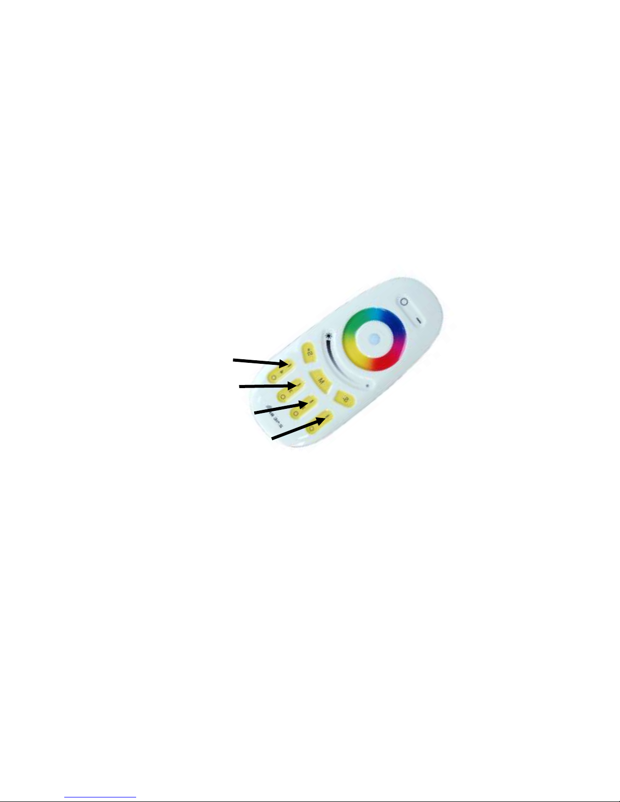
press one of the four channels’ “ON” buttons of the handheld Remote Control. The four buttons are
pointed out below.
Channel 1
Channel 2
Channel 3
Channel 4
NOTE: If the floor panel is new, or does not respond to the remote control, skip steps 1 thru 3.
STEP 1:
Changing or reprograming to a new channel will always require that the Floor Panel is first
unprogrammed from the channel it is currently assigned. To establish what channel the panel is
currently assigned, simply press the on and off button of each channel until the panel responds.
STEP 2:
Disconnect the Floor Panel from power and then reconnect. Within 3 seconds press and hold the “ON”
button of the currently assigned channel.
STEP 3:
If successful, ILLUMA SQUARE will flash white 9 times quickly. If not, repeat steps 1 and 2.
STEP 4:
Disconnect the panel from power.
STEP 5:
Reconnect to power and within 3 seconds, press once (do not hold) the “ON” button of the channel you
want the panel to be assigned to.
STEP 6:
If successful, ILLUMA SQUARE will flash white slowly 2 times. If not, repeat steps 4 and 5.
Copyright USA Dance Floor, LLC

10
ASSEMBLY INSTRUCTIONS
All parts are secured together by one-inch, #2 Standard Phillips Head stainless-steel screws. All screws
should only be “started” and kept loose during assembly as shown in Figure A. Keeping the screws loose
will keep the Floor Panels free to move during assembly.
Only after all the screws have been started the screws may be Secured.
Securing a screw does not mean tighten it. Securing a screw means that the top of the
screw’s head is level with or below the floor surface as shown in Figure B.
Figure A
Dance Floor surface
The cutaway drawing on the right shows
the screw in the “started” position.
Figure B
This drawing shows the screw in the
“secured” position. Notice there is room
to allow for flexing and movement.
Figure C
This drawing shows the screw too tight.
This will void any warranty.
NOTE: A power drill may be used to secure screws only if it has a ratchet drive set at low torque.
Copyright USA Dance Floor, LLC

11
STEP BY STEP ASSEMBLY:
Steps 1 thru 5 will get your first floor panel connected and functional. If you plan to
change the programmed channel, it should be done during step 4.
1 Step 1: Plug the Power Supply into a standard wall outlet
Step 2: Connect the Main Power Trim to the Power Supply
Power Supply 2
Main Power Trim
Step 3: Connect the Power Trim to the Main Power Trim 3
Floor Panel
Power Trim
Step 4: Connect the first Floor Panel to the Power Trim 4
5Step 5: Using two stainless steel screws, attach the trim pieces to the Floor Panel
Copyright USA Dance Floor, LLC

12
ASSEMBLY ORIENTATION: To the Power Supply
After completing the first five steps you will have the first floor
panel installed and functioning. It should look like this drawing.
The drawing below shows the first panel
(in the upper right-hand) and it shows how to assemble the rest of
your system. This is the repeated process for any size or arrangement. To the Power Supply
NON-POWER
TRIM
POWER
TRIM

13
FINAL STEP & NOTES
ARRAIGNMENTS:
Remember you can arrange your floor to form a square, rectangle, or runway. Pictured below are only a
few ideas.
FINISHING STEP:
Once all the Floor Panels are connected and the screws have been “Started”, it is time to secure all of
the screws and attach the optional aluminum beveled edging. Remember; securing a screw means that
the top of the screw’s head is level with or below the floor surface. Do not tighten screws as explained
under, “ASSEMBLY INSTRUCTIONS” on page 10 of this manual.
NOTE: A power drill may be used to secure screws only if it has a ratchet drive set at low torque
You should be ready to go. Have fun!
NOTE: If you have the optional Beveled Edging and you are arranging a floor with inside corners, such as
an “L” or “T” shape, beveled inside corner sets are available at www.illumasquare.com
CLEANING & MAINTENANCE:
ILLUMA SQUARE is recommended for inside use only. You may setup ILLUMA SQUARE on any flat hard
surface.
Floor panels are water resistant but not waterproof. You may spill drinks and wet mop. All that is
needed to clean the acrylic surface is water and a clean rag. Never use anything abrasive.
Whatever does not come off with water can be easily removed with “Goof Off” remover and a clean rag.
We have tested many cleaners and recommend “Goof Off” brand professional strength remover (in the
yellow can). It can be used to clean any parts of the floor panels and trim. Simply wet a clean rag with
Goof Off and wipe.
ILLUMA SQUARE is a product of USA Dance Floor, LLC
Copyright USA Dance Floor, LLC

14
Copyright USA Dance Floor, LLC
This manual suits for next models
1
Table of contents
Popular Dj Equipment manuals by other brands

Velleman
Velleman HQ Power Mini Mushroom 6 X 3 RGBWA user manual

Memorex
Memorex MKA320 operating instructions

Velleman
Velleman HQ Power HQLP10007 user manual

ColorMaker
ColorMaker PS500 manual

Chauvet Professional
Chauvet Professional Rogue R2 Wash VW Quick reference guide

Laserworld
Laserworld RTI NEO SIX RGB 2 manual