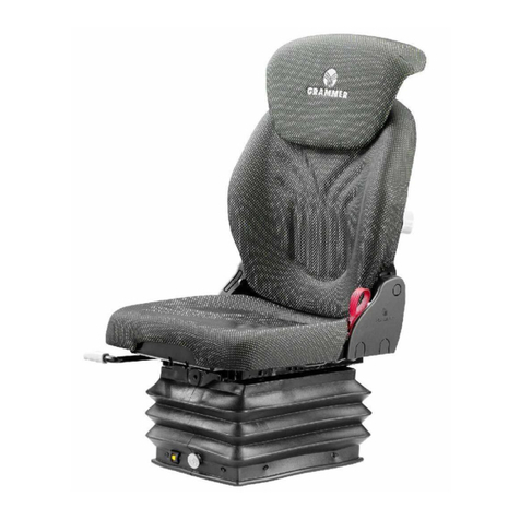
USA Standard Gear Spartan Locker User manual

II
Also available from USA Standard Gear:
• Ring & Pinion Sets • Master Overhaul Kits • Small Parts
• Axles • OE Replacement Driveshafts
• Manual Transmission & Transfer Case Components
General Spartan Locker Installation Manual .......... 2
Preparing the vehicle for installation .................................................2
Carrier removal .....................................................................................2
Removal of spider gears.......................................................................3
Installing your Spartan Locker.............................................................3
Final Installation Steps – Carrier in vehicle........................................6
Final Installation Steps – Carrier out of vehicle.................................6
Suzuki Samurai Installation Manual........................ 7
Preparing the vehicle for installation .................................................7
Carrier removal and teardown ............................................................8
Installation Steps:..................................................................................8
Final Installation Steps ......................................................................11
Toyota V6 Installation Manual ................................12
Preparing the vehicle for installation ...............................................12
Carrier removal and teardown ..........................................................13
Installation Steps:................................................................................13
Final Installation Steps ......................................................................16
Ford 8” & 9” Installation Manual............................17
Side Gear & Driver Height Verification ............................................. 17
Preparing the Vehicle for Installation ...............................................18
Carrier Removal and Teardown.........................................................18
Installation Steps for 4 Pinion Ford 9” Rear Axles: .........................18
Installation Steps for 2 Pinion Ford 8” or 9” Rear Axles: ...............20
Final Installation Steps ......................................................................21
Contents
© USA Standard Gear

2 3
General Spartan Locker Installation Manual
Note about your carrier: Before beginning to tear down your differential,
please be aware that the Spartan Locker is designed to fit open carriers only. It
will not install into any type of limited slip carrier.
Preparing the vehicle for installation
Take the following steps to prepare your vehicle for installation:
• Block the vehicle’s tires, and place the transmission in neutral.
• Loosen the lug nuts and jack the vehicle up.
• Make sure that the vehicle is securely resting on jack stands.
• Remove the wheels, disconnect the brake lines and emergency brake cables.
• Remove the differential cover (if it is not a third member style differential),
and drain the oil.
• Slide out both axles to provide enough clearance to remove the carrier, if
necessary. This requires the removal of C-clips, if present.
• Check your ring gear to see if there is enough clearance to remove the
cross pin shaft. If there is not enough clearance, please take the steps in the
following section to remove your carrier.
Carrier removal
If you are running a low ratio ring & pinion set, such as a 4.88 or 5.13, you
may find that your ring gear is too thick to allow for removal of the cross pin
shaft. If this is the case, please take the following steps:
• Using a punch, mark one of the bearing caps so you can remember which
side it belongs to. Bearing caps are specific to each side of the housing. This
is very important for re-assembly. Figure 1-A
• Check your backlash with a dial indicator and make note of it. You will need
to check it again later after re-assembly to make sure everything went back
together properly.
• Remove your bearing caps, and pull out your carrier. Some designs have
shims outside the races. You must keep track of which side you removed the
shims from; they must be returned to the same sides they were removed
from. This is also true for the carrier races.
• Remove your ring gear from the carrier.
Removal of spider gears
*Note: If you were able to remove the cross pin shaft without having to
remove the ring gear, the following process can be performed with the carrier
still in the differential housing.
• Remove your cross pin shaft retaining pin or bolt.
• Remove the cross pin shaft and inspect it for damage. If it shows excessive wear
or damage, purchase a new shaft prior to installation of your Spartan Locker.
• Remove your spider gears and thrust washers.
• Thoroughly clean the inside of the carrier and dry it. Inspect for any cracks
or excessive wear. If the carrier is damaged or worn, replace it prior to
installation of your Spartan Locker.
Installing your Spartan Locker
• Place a spring into the hollow end of each of the alignment pins, set aside.
Figure 2-A
• Install the four alignment pin/spring assemblies into the respective driver
holes. Figure 3-A
• Push each alignment pin/spring assembly fully down into the driver and
insert the retainer wire into retainer wire hole in the driver to hold the
alignment pin/spring assembly down. Figure 4-A
• Install side couplers into carrier case. DO NOT use thrust washers.
Figure 5-A
Figure 1-A

4 5
Figure 2-A
• Install the spacers into the centers of each driver, Making sure that the
“open” face of the spacer is positioned toward the driver’s teeth. Figure 6-A
• Take one of the center drivers, with the spacer placed in it, and install it into
the carrier. Figure 7-A
• Rotate the drivers until the alignment pin/spring assemblies line up with
corresponding alignment pin seating notches in the opposite driver.
•
Pull the alignment pin/spring assembly retainer wire out of one of the alignment
pin/spring assemblies using a suitable tool, allowing the assembly to extend
fully into the seating notch in the opposite driver. Figure 8-A
• Repeat process for the remaining three alignment pin/spring assemblies.
Note: Retaining wire may need to be bent along side the Spartan drivers to be
properly installed in some cases.
Center Gap Measurement
1. With the Spartan components fully installed measure the distance between
the two Spartan drivers using a set of feeler gauges or slide caliper.
Distance should measure between .145 and .170 in.
2. If measurement does not fall within range check installation procedure and
product for potentials obstructions.
Figure 3-A Figure 4-A
Figure 5-A Figure 6-A
Figure 7-A Figure 8-A

6 7
Final Installation Steps – Carrier in vehicle
• Install the cross pin shaft and retaining pin.
• Finish assembly by reconnecting brake lines, backing plates, tires, etc.
• Check installation by putting the vehicle in gear and in 4wd if installing in a
front application.
• Rotate one tire forcefully until it stops against the drivetrain. This must be
done in both directions on each side.
• Have a second person rotate the opposite tire in the opposite direction, It
should unlock and spin.
• Your Spartan locker should make a clicking sound as the teeth move over
each other. If this sound is not present, or you cannot get the teeth to disen-
gage at all, check your work.
• Once everything is correctly installed, and the locker has been tested, attach
the differential cover (if your vehicle has one) using a gasket or black RTV
silicone and tighten all the cover bolts.
• Add gear oil.
Final Installation Steps – Carrier out of vehicle
• Thoroughly clean the housing.
• Place the carrier cares on same sides they were removed from.
• Install the carrier into the housing. If outside carrier shims were present,
install them into the same sides they were removed from.
• Replace bearing caps to their correct sides, torque down bolts to the proper
amount. Consult shop manual for the torque specification.
• Finish assembly by reconnecting brake lines, backing plates, tires, etc.
•
Check locker operation as described in Final Installation Steps – Carrier in
vehicle.
•
Once everything is correctly installed, attach the differential cover (if your vehicle
has one) using a gasket or black RTV silicone and tighten all the cover bolts.
• Add gear oil.
**Note about tire diameters**
For safety and long life of your Spartan Locker, it is important that your tire di-
ameters are as close to identical as possible. Differing tire sizes can cause pre-
mature wear to your Spartan Locker, shortening its life and causing possible
damage to your differential. Measure each tire to make sure that they match
from the ground to the top of the wheel, adjusting tire pressure as necessary.
Note about your carrier: Before beginning to tear down your differential,
please be aware that the Spartan Locker is designed to fit open carriers only. It
will not install into any type of limited slip carrier.
Note about thrust washers: This Spartan Locker does not use the side gear
thrust washers. Attempting to install or operate the unit with thrust washers
present may damage the unit or your case.
This Spartan Locker design comes with the following components: Figure 1-B
• Two (2) Drivers
• One (1) Long cross pin shaft
• Two (2) Short cross pin shafts
• Four (4) Alignment pins
• Four (4) Springs
• Two (2) Spacers
Preparing the vehicle for installation
Take the following steps to prepare your vehicle for installation:
• Block the vehicle’s tires, and place the transmission in neutral.
• Loosen the lug nuts and jack the vehicle up.
• Make sure that the vehicle is securely resting on jack stands.
• Remove the wheels; disconnect the brake lines and emergency brake cables.
•
Slide out both axles to provide enough clearance to remove the carrier, if needed.
• Remove the dropout from the axle housing.
Suzuki Samurai Installation Manual

8 9
Figure 1-B Figure 2-B
Figure 3-B - MUST REMOVE thrust washers Figure 4-B
Figure 5-B Figure 6-B
Carrier removal and teardown
• Using a punch, mark one of the bearing caps so you can remember which
side it belongs to. Bearing caps are specific to each side of the housing. This
is very important for re-assembly.
• Check your backlash with a dial indicator and make note of it. You will need
to check it again later after re-assembly to make sure everything went back
together properly.
• Remove bearing caps, and pull out carrier.
• Remove ring gear from the carrier.
• Loosen carrier case bolts and remove the carrier hat.
• Remove cross pin shafts, spider gears and thrust washers. Figure 2-B & 3-B
• Clean carrier case and side gears thoroughly.
• Inspect carrier case and side gears for excessive wear. If the carrier or side
gears are damaged or worn excessively, your Spartan Locker may not work
properly or could be damaged.
• Prior to beginning the installation process, check the side gear fit in carrier
hat with the thrust washer removed to make sure it spins freely. Figure 4-B
Installation Steps:
• Place springs into the alignment pins. Figure 5-B
• Carefully install the alignment pins and springs into the holes in the back
of the drivers. Make sure the springs do not fall out or become wedged
sideways in the holes during installation. Figure 6-B
• Stack the drivers together as they would sit in the carrier case. Figure 7-B
• Install the first side gear into the carrier case. Figure 8-B
• Install the drivers together into the carrier case. Figure 9-B
• Place first spacer on top of the bottom side gear. Figure 10-B
• Install cross pin block. Figure 11-B
• Install all three cross pin shafts. Figure 12-B
• Place the second spacer on top of the cross pin block. Figure 13-B
• Install the second spider gear on top of the driver. Figure 14-B
• Place carrier hat on top of carrier and push down to make sure the hat seats
completely against the carrier. Figure 15-B
• Install carrier case bolts and tighten down.
• Mount and install the ring gear.
• Install and torque down ring gear bolts. Consult shop manual for
torque specifications.

10 11
Figure 7-B Figure 8-B
Figure 9-B
Final Installation Steps
• Thoroughly clean the housing.
• Place the carrier races on same sides they were removed from.
• Install the carrier into the housing.
• Replace bearing caps to their correct sides, torque down bolts to the proper
specification. Consult shop manual for the torque specification.
• Adjust backlash and tighten down side adjusters. Consult shop manual for
proper bearing preload specification.
• Finish assembly by reconnecting brake lines, backing plates, tires, etc
• Check installation by putting the vehicle in gear and in 4wd if installing in a
front application.
•
Rotate one tire forcefully until it stops against the drivetrain. Repeat engagement/
disengagement testing for both direction on each side of the vehicle.
• Have a second person rotate the opposite tire in the opposite direction, It
should unlock and spin.
• Your Spartan locker should make a clicking sound as the teeth move over
each other. If this sound is not present, or you cannot get the teeth to
disengage at all, check your work.
• Add gear oil.
Figure 10-B
Figure 11-B Figure 12-B
Figure 13-B
Figure 14-B Figure 15-B

12 13
Toyota V6 Installation Manual
Note about your carrier: Before beginning to tear down your differential,
please be aware that the Spartan Locker is designed to fit open carriers only. It
will not install into any other type of carrier.
Note about thrust washers: This Spartan Locker does not use the side gear
thrust washers. Attempting to install or operate the unit with thrust washers
present may damage the unit or your case. Figure 1-C
This Spartan Locker design comes with the following components:
• Two (2) Drivers
• Four (4) Alignment pins
• Four (4) Springs
• Two (2) Spacers
Preparing the vehicle for installation
Take the following steps to prepare your vehicle for installation:
• Block the vehicle’s tires, and place the transmission in neutral.
• Loosen the lug nuts and jack the vehicle up.
• Make sure that the vehicle is securely resting on jack stands.
• Remove the wheels; disconnect the brake lines and emergency brake cables,
if needed.
• Slide out both axles to provide enough clearance to remove the carrier.
• Remove the dropout from the axle housing.
Carrier removal and teardown
•
Using a punch, mark one of the bearing caps so you can remember which side
it belongs to. Bearing caps are specific to each side of the housing. This is very
important for re-assembly.
•
Check your backlash with a dial indicator and make note of it. You will need to
check it again later after re-assembly to make sure everything went back
together properly.
• Remove bearing caps, and pull out carrier.
• Make note of the bearing races as they will need to be reinstalled on the
same side they came off of.
• Loosen carrier case bolts and remove the top half of the carrier. Figure 2-C
• Remove cross pin shaft, spider gears and thrust washers.
• Clean carrier case and side gears thoroughly.
• Inspect carrier case and side gears for excessive wear. If the carrier or side
gears are damaged or worn excessively, your Spartan Locker may not work
properly or could be damaged.
Installation Steps:
• Place springs into the alignment pins. Figure 3-C
• Carefully install the alignment pins and springs into the holes in the back of the
drivers. Make sure the springs do not fall out or become wedged sideways in
the holes during installation. Figure 4-C
•
Install the first side gear into the carrier case, without the thrust washer. Figure 5-C
• Place first driver onto side gear. Figure 6-C
• Place first spacer on top of the bottom side gear. Figure 7-C & 8-C
• Install cross. Figure 9-C
• Place the second driver on top of the cross. The alignment pins in each driver
must fall into the slots of the opposing driver. Figure 10-C
• Install the second spacer. Figure 11-C & 12-C
•
Install the 2nd side gear on top of the driver, without the thrust washer. Figure 13-C
• Place top carrier half onto carrier assembly. Figure 14-C
• Install carrier case bolts and tighten down. Consult shop manual for
torque specifications.
Figure 1-C Figure 2-C

14 15
Figure 3-C Figure 9-C
Figure 5-C Figure 11-C
Figure 7-C Figure 13-C
Figure 4-C Figure 10-C
Figure 6-C Figure 12-C
Figure 8-C Figure 14-C

16 17
Final Installation Steps
• Thoroughly clean the housing.
• Place the carrier races on same sides they were removed from.
• Install the carrier into the housing.
• Replace bearing caps to their correct sides, torque down
bolts to the proper specification. Consult shop manual for the
torque specification.
• Adjust backlash and tighten down side adjusters. Consult shop
manual for proper bearing preload specification.
• Finish assembly by reconnecting brake lines, backing plates, tires, etc
• Check installation by putting the vehicle in gear and in 4WD if
installing in a front application.
•
Rotate one tire forcefully until it stops against the drivetrain. Have a
second person rotate the opposite tire in the opposite direction, It
should unlock and spin.
• Repeat engagement/disengagement testing for both directions on
each side of the vehicle.
•
Your Spartan locker should make a clicking sound as the teeth move
over each other. If this sound is not present, or you cannot get the
teeth to disengage at all, check your work.
• Repeat engagement/disengagement testing as indicated above.
• Add gear oil.
**Note about tire diameters**
For safety and long life of your Spartan Locker, it is important that
your tire diameters are as close to identical as possible. Differing tire
sizes can cause premature wear to your Spartan Locker, shortening
its life and causing possible damage to your differential. Measure
each tire to make sure that they match from the ground to the
top of the wheel.
Ford 8” & 9” Installation Manual
Note about your carrier: Before beginning to tear down your differential,
please be aware that the Spartan Locker is designed to fit open carriers only. It
will not install into any other type of carrier.
Note about thrust washers: This Spartan Locker does not use the side gear
thrust washers. Attempting to install or operate the unit with thrust washers
present may damage the unit or your case.
This Spartan Locker design comes with the following components:
• Two (2) Drivers
• Four (4) Alignment Pins
• Four (4) Springs
• One (1) Center Block
• One (1) Large Cross Pin
• Two (2) Small Cross Pins
• Two (2) Extra Small Cross Pins
• Three (3) Roll Pins
Side Gear & Driver Height Verification
Place your stock side gear on the driver as shown below and verify that the height
is more than 1.1950” without the thrust washer in place. The thrust washers will
not be used in the installation. If the height is less than what is indicated you must
purchase new side gears; part # FORF900301 for 31 spline axles and FORF900303
for 28 spline axles. (2 of each are required per application)

18 19
Preparing the Vehicle for Installation
Take the following steps to prepare your vehicle for installation:
• Block the vehicle’s tires, and place the transmission in neutral.
• Loosen the lug nuts and jack the vehicle up.
• Make sure that the vehicle is securely resting on jack stands.
• Remove the wheels; disconnect the brake lines and emergency brake cables,
if needed.
• Slide out both axles to provide enough clearance to remove the dropout.
• Remove the dropout from the axle housing.
Carrier Removal and Teardown
• Using a punch, mark one of the bearing caps so you can remember which side
it belongs to. Bearing caps are specific to each side of the housing. This is very
important for re-assembly.
• Check your backlash with a dial indicator and make note of it. You will need
to check it again later after re-assembly to make sure everything went back
together properly.
• Remove bearing caps, and pull out carrier.
• Make note of the bearing races as they will need to be reinstalled on the
same side they came off of.
• Remove roll pins and separate the carrier.
• Remove cross pin shaft, spider gears and thrust washers.
• Clean carrier case and side gears thoroughly.
• Inspect carrier case and side gears for excessive wear. If the carrier or side
gears are damaged or worn excessively, your Spartan Locker may not work
properly or could be damaged.
Installation Steps for 4 Pinion Ford 9” Rear Axles:
• Place springs into the alignment pins. Figure 1-D
• Carefully install the alignment pins and springs into the holes in the back of
the drivers. Make sure the springs do not fall out or become wedged side-
ways in the holes during installation. Figure 2-D
•
Install the first side gear into the carrier case, without the thrust washer. Figure 3-D
• Place first driver onto side gear. Figure 4-D
• Install center block. Figure 5-D
• Take note of roll pin holes in case
• Install large cross pin lining up hole in pin with hole in case. Figure 6-D
• Install small cross pins aligning hole in pins with holes in case. Figure 7-D
• Place the second driver on top of the cross. The alignment pins in each driver
must fall into the slots of the opposing driver. Figure 8-D
• Install the second side gear on top of the driver, without the thrust washer.
Figure 9-D
• Place top carrier half onto carrier assembly. Figure 10-D
Figure 1-D
Figure 3-D
Figure 5-D
Figure 7-D
Figure 2-D
Figure 4-D
Figure 6-D
Figure 8-D

20 21
• Install roll pins. Figure 11-D
Installation Steps for 2 Pinion Ford 8” or 9” Rear Axles:
• Place springs into the alignment pins. Figure 12-D
• Carefully install the alignment pins and springs into the holes in the back of
the drivers. Make sure the springs do not fall out or become wedged side-
ways in the holes during installation. Figure 13-D
• Install the first side gear into the carrier case, without the thrust washer.
Figure 14-D
• Place first driver onto side gear. Figure 15-D
•
Install center block with (2) extra small cross pins on opposite sides. Figure 16-D
• Take note of roll pin hole in case. Figure 17-D
• Install large cross pin lining up hole in pin with hole in case. Figure 18-D
• Place the second driver on top of the cross. The alignment pins in each driver
must fall into the slots of the opposing driver. Figure 19-D
• Install the second side gear on top of the driver, without the thrust washer.
Figure 20-D
• Place top carrier half onto carrier assembly. Figure 21-D
• Install roll pin. Figure 22-D
Final Installation Steps
• Thoroughly clean the housing.
• Place the carrier races on same sides they were removed from.
• Install the carrier into the housing.
• Replace bearing caps to their correct sides, torque down bolts to the proper
specification. Consult shop manual for the torque specification.
• Adjust backlash and tighten down side adjusters. Consult shop manual for
proper bearing preload specification.
• Finish assembly by reconnecting brake lines, backing plates, tires, etc
• Rotate one tire forcefully until it stops against the drivetrain. Have a second
person rotate the opposite tire in the opposite direction, It should unlock
and spin.
• Repeat engagement/disengagement testing for both directions on each side
of the vehicle.
• Your Spartan locker should make a clicking sound as the teeth move over
each other. If this sound is not present, or you cannot get the teeth to
disengage at all, check your work.
• Repeat engagement/disengagement testing as indicated above.
• Add gear oil.
**Note about tire diameters**
For safety and long life of your Spartan Locker, it is important that your tire diameters are as
close to identical as possible. Differing tire sizes can cause premature wear to your Spartan
Locker, shortening its life and causing possible damage to your differential. Measure each tire
to make sure that they match from the ground to the top of the wheel.
Figure 9-D
Figure 11-D
Figure 13-D
Figure 15-D
Figure 14-D
Figure 16-D
Figure 12-D
Figure 10-D

22 23
Figure 17-D
Figure 19-D
Figure 21-D
Figure 18-D
Figure 20-D
Figure 22-D
Table of contents