Utile 675A Guide

GAS COMPRESSORS / BOOSTERS GAS & AIR MIXING SYSTEMS AIR BLOWERS & VACUUM PUMPS
The Utile Engineering Co. Ltd. Irthlingborough, Northamptonshire, NN9 5UG, ENGLAND
Telephone: + 44 (0) 1933 650216 Facsimile: + 44 (0) 1933 652738 Email: [email protected] www.utileengineering.com
Feb-19 1 IC013 Rev2
Installation
Operation
Maintenance Instructions
Model 675A
Centrifugal
Blowers /Exhausters
& Gas Boosters
Serial Number
Site Location
Installation Date

GAS COMPRESSORS / BOOSTERS GAS & AIR MIXING SYSTEMS AIR BLOWERS & VACUUM PUMPS
The Utile Engineering Co. Ltd. Irthlingborough, Northamptonshire, NN9 5UG, ENGLAND
Telephone: + 44 (0) 1933 650216 Facsimile: + 44 (0) 1933 652738 Email: [email protected] www.utileengineering.com
Feb-19 2 IC013 Rev2
Page
General ……………………………………………………………………………………………………………… 3
Operating Principle ………………………………………………………………………………………………… 3
Health and Safety ……………………………………………………………………………………………………………… 4
Atex ……………………………………………………………………………………………………………… 6
Technical Specification ………………………………………………………………………………………………… 7
Packaging ……………………………………………………………………………………………………………… 7
Storage ……………………………………………………………………………………………………………… 8
Handling …………………………………………………………………………………………………………………………… 8
Installation ……………………………………………………………………………………………………………… 8
Installation - Drive ………………………………………………………………………………………………… 10
Pipework ……………………………………………………………………………………………………………… 12
Vibration ……………………………………………………………………………………………………………… 12
Noise …………………………………………………………………………………………………………………………… 13
Leakage Rates ……………………………………………………………………………………………………………… 13
Protective Devices ………………………………………………………………………………………………… 13
Pre Start-up Checks ………………………………………………………………………………………………… 14
Start-up ……………………………………………………………………………………………………………… 14
Operating Notes ……………………………………………………………………………………………………………… 14
Stopping Procedure ………………………………………………………………………………………………… 14
Lubrication ……………………………………………………………………………………………………………… 14
Maintenance ……………………………………………………………………………………………………………… 15
Troubleshooting ………………………………………………………………………………………………… 17
To Dismantle ……………………………………………………………………………………………………………… 18
Reassembly ……………………………………………………………………………………………………………… 18
Spare Parts ……………………………………………………………………………………………………………… 19
After Sales Service ………………………………………………………………………………………………… 19
Spare Parts List ………………………………………………………………………………………………… 20
Warranty ……………………………………………………………………………………………………………… 21
Installation & Commissioning Check Sheet ………………………………………………………… 22
Logbook Check Sheet ………………………………………………………………………………………………… 23
Warning
Read the installation and maintenance information before commencing work on this equipment. Your attention is drawn to
the health and safety information on page 4. Until the equipment into which the machine has been incorporated and the
said equipment declared to be in conformity with the Machinery Directive, they must not be put into service.
Foreword
The 675 series centrifugal gas booster has been developed based on many years of experience in the booster and exhauster industry.
Using modern design techniques and production methods coupled with rigorous testing and high quality standards ensure this series of
machines have a long, efficient and reliable service life.
These operating instructions have been written for all personnel who have responsibility to the machine, it contains all the necessary
information required for the machine to have a long trouble free service life. This manual must be stored near the machine and read
before attempting any work on it.
Ensure that all operation and maintenance is only performed by competent and trained personnel and any repairs use only original
parts from the manufacturer.
Contents

GAS COMPRESSORS / BOOSTERS GAS & AIR MIXING SYSTEMS AIR BLOWERS & VACUUM PUMPS
The Utile Engineering Co. Ltd. Irthlingborough, Northamptonshire, NN9 5UG, ENGLAND
Telephone: + 44 (0) 1933 650216 Facsimile: + 44 (0) 1933 652738 Email: [email protected] www.utileengineering.com
Feb-19 3 IC013 Rev2
General
The normal routine of running the machine is very simple. If it is carried out strictly at all times, many years of trouble free service can
be expected.
We emphasise three points of paramount importance-
1. Filtration of incoming air of gas 2. Lubrication 3. Temperature monitoring
It is essential that the compressor/booster is installed, commissioned and maintained correctly. To assist with this an
installation/commissioning check sheet, and a sample logbook record sheet is found at the back of this manual. If the operator can
enter daily/weekly readings into the logbook, with regular logbook readings along with the check sheet completed on installation can
then show whether the machine is performing as it did originally.
Operating Principle
Centrifugal pumps, work as their name suggests by centrifugal force driving outwards from the centre of rotation. They provide a
constant, low-pulsation supply of air or gas.
The machines have an impeller rotating inside a volute casing. The air/gas enters at the eye (centre) of the impeller, and is thrown out
to the edge of the casing by centrifugal force as the impeller rotates (fig 1) and is discharged through the machine outlet.
The impeller has a number of curved vanes fitted to either one or fitted between two side plates (fig 2) to generate the centrifugal
force when the impeller is rotated at high speed.
Some boosters has multi-stages, following the same principle through each stage, the main advantage of multi-stage pumps is that
they are able to achieve higher delivery pressures, which allows greater flexibility in variations of flow and pressures
The machine can only be run in one direction, which is indicated by an arrow on the casing. The direction of rotation must not be
reversed.
General
Operating Principle
Fig. 1
Fig. 2

GAS COMPRESSORS / BOOSTERS GAS & AIR MIXING SYSTEMS AIR BLOWERS & VACUUM PUMPS
The Utile Engineering Co. Ltd. Irthlingborough, Northamptonshire, NN9 5UG, ENGLAND
Telephone: + 44 (0) 1933 650216 Facsimile: + 44 (0) 1933 652738 Email: [email protected] www.utileengineering.com
Feb-19 4 IC013 Rev2
Read the installation and operating instructions carefully.
Various codes of practice are in existence and users must ensure that adequate precautions are taken to prevent a health
hazard to employees or third party.
All personnel working in or passing through the area should be adequately warned by
signs and trained to exercise appropriate safety precautions. Ensure the correct
personal protective equipment is worn at all times.
Certain machinery can generate high levels of noise which can be harmful if exposed to it for lengthy periods of time.
Hearing protectors must be used when working/operating near the machinery.
Rotating machinery and pressurised components, which may contain toxic, flammable or otherwise hazardous media are
potentially dangerous equipment if not operated and maintained correctly. It is imperative that all users of such equipment
fully educate themselves to the potential dangers and satisfy themselves that the personnel responsible for installing,
testing, commissioning, operating and maintaining the plant are competent to do so. Instruction manuals are provided for
guidance but must assume some basic level of competence by users. If there are any doubts or ambiguities concerning
correct procedures, ask Utile Engineering. DO NOT TAKE RISKS.
Equipment with internal pressures above or below ambient pressures can create a hazard. Before attempting to investigate
problems, service or maintain equipment, it must be safely depressurised or pressurised to ambient conditions.
Also since the gaseous medium may be flammable, toxic, corrosive or otherwise hazardous it may be necessary to purge
the installation with an inert gas, such as nitrogen. Special precautions are necessary for certain gases and the user must
ensure that adequate procedures are implemented.
Moving parts of machinery must not be touched and all such parts must be adequately guarded. Suitable guards are
provided and must be securely retained in position at all times.
Before commencing maintenance, servicing or making other adjustments, the prime mover and other equipment must be
isolated electrically or otherwise immobilised to prevent accidental start-up. In this vein, a fully qualified electrician should
carry out all electrical work and all electrical equipment should be isolated before it is touched and pneumatic or hydraulic
controls depressurised and made safe. Procedures must also exist to ensure that electrical or other inputs cannot be
restored accidentally during the maintenance or service period.
Safety trips, emergency stop-buttons and other such devices (if fitted) are to be checked regularly to ensure that they
continue to function correctly and will protect the installation and personnel in the event of an emergency.
NO attempt should be made to touch the machine whilst it is rotating. Particular care is needed when checking rotor
clearances. Any movement of rotors may trap fingers.
Most machines, certain pipes and ancillaries become hot during operation whilst certain machines with sub-zero inlet
temperatures may result in very cold surfaces. If it is possible for personnel to come into contact with such surfaces
unknowingly or accidentally they should be guarded.
Before any maintenance work commences the machine should have cooled to ambient temperature.
Health and Safety
Health and Safety

GAS COMPRESSORS / BOOSTERS GAS & AIR MIXING SYSTEMS AIR BLOWERS & VACUUM PUMPS
The Utile Engineering Co. Ltd. Irthlingborough, Northamptonshire, NN9 5UG, ENGLAND
Telephone: + 44 (0) 1933 650216 Facsimile: + 44 (0) 1933 652738 Email: [email protected] www.utileengineering.com
Feb-19 5 IC013 Rev2
If severe vibration is observed, the cause of this should be immediately investigated and the situation rectified. Excessive
vibration can lead to fatigue and other failures. Similarly, if during operation a significant change is noticed in the level of
vibration, noise, temperature or any other parameter, the cause of such changes must be determined, and the cause
rectified.
Inlet filters must be inspected regularly so that liquid or debris is not allowed to enter the machine, which could cause
damage and consequently injury to personnel.
During routine maintenance, coupling alignment should be checked for misalignment.
Only approved lubricants must be used and quantities, etc must be checked regularly.
Before restarting after servicing, all nuts, set screws, etc must be checked for tightness, check all joints, for leaks and
carry out purging as necessary before introducing the process gas.
Also, before start-up, check the machine inlet and outlet isolating valves are open both non-return valves (if fitted) are
the correct orientation.
Adjacent pipework and equipment must not impose undue forces and moments on the machinery flanges.
All welding work must be carried out be an approved gas coded welder.
In order to prevent reverse rotation of machines, it is ESSENTIAL that a non-return valve be installed in the inlet
pipework. Otherwise a hazardous situation can arise during a normal shutdown or if the prime mover power supply is
interrupted for a period of time.
The environment around the installation may need to be monitored in order to detect gas leaks etc., and consideration
must be given to the installation of gas detecting equipment, and the class of electric equipment.
If installation components are only accessible using a pedestal or stairs, then this pedestal or stair may present a falling
hazard. Secure the pedestal or stair with a railing or handrail!
The environment around the installation may need to be monitored in order to detect trip hazards. Tubes, cables etc. laid
around the floor may cause a tripping hazard.
Leakages of hazardous fluids from shaft seals can occur, these should be contained, to avoid any harm to personnel or
the environment.
Care must be taken when dismantling the machine as there may be possible harmful substances from the pumping media
remaining in the compressor/booster.
If the machine is located in a hazardous or zoned area, it is important to prevent unauthorised modes of operation.
Failure to do so may result in the temperature limits being exceeded.
Health and Safety

GAS COMPRESSORS / BOOSTERS GAS & AIR MIXING SYSTEMS AIR BLOWERS & VACUUM PUMPS
The Utile Engineering Co. Ltd. Irthlingborough, Northamptonshire, NN9 5UG, ENGLAND
Telephone: + 44 (0) 1933 650216 Facsimile: + 44 (0) 1933 652738 Email: [email protected] www.utileengineering.com
Feb-19 6 IC013 Rev2
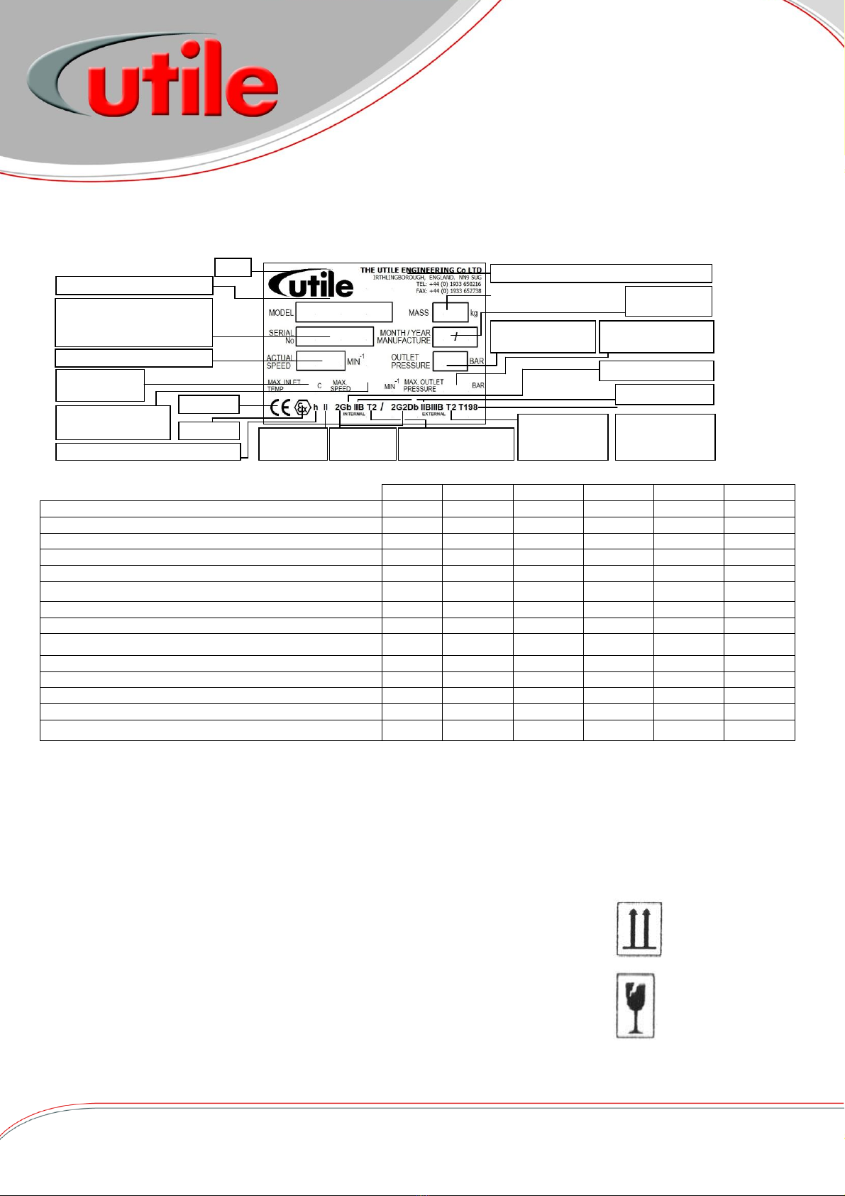
Temperature Classification
Temperature
Class
Maximum Surface
Temperature(°C)
T1
450
T2
300
T3
200
T4
135
T5
100
T6
85
ATEX
Atex from the French Atmospheres EXplosibles. It means a hazardous or potentially explosive environments, both gaseous and dusts.
For an explosion to take place, three basic requirements must be fulfilled. These are a flammable substance, oxygen or air and a
source of ignition such as a spark.
When all intake and discharge pipework and therefore all machine wetted parts are completely filled with the process fluid during
normal operation, an explosive atmosphere is prevented from occurring. If this condition cannot be guaranteed, then any appropriate
monitoring devices must be used by the user
Atex Coding
Atex Equipment group
Equipment for potentially explosive atmospheres is divided into 2 groups,
Group I equipment for mining
Group II equipment for non-mining areas with potentially explosive atmospheres.
Atex Equipment Categories and Zones
The degree of danger varies from extreme to rare. Hazardous areas are classified into three Categories and six Zones as follows: -
Category 1 –Zone 0 is which an explosive gas/air mixture is continuously present or present for long periods.
Category 1 –Zone 20 is which a combustible dust/air mixture is continuously present or present for long periods.
Atex equipment category 1G (gas) or 1D (dust).
Equipment in this category shall have a sufficient level of protection even in the event of a rare malfunction.
Category 2 –Zone 1 is which an explosive gas/air mixture is likely to occur in normal operation.
Category 2 –Zone 21 is which a combustible dust/air mixture is likely to be present in normal operation.
Atex equipment category 2G (gas) or 2D (dust).
Equipment in this category shall have a sufficient level of protection for normal operation and expected malfunctions.
Category 3 –Zone 2 is which an explosive gas/air mixture is not likely to occur in normal operation and if it occurs it will only exist for
a short time.
Category 3 –Zone 22 is which a combustible dust/air mixture is not likely to occur in normal operation, but if it is present it will only
exist for a short time.
Atex equipment category 3G (gas) or 3D (dust).
Equipment in this category shall have a sufficient level of protection for normal operations.
An area that is not classified Zone 0, 1, 2, 20, 21 or 22 is deemed to be a non-hazardous or safe area.
Gas and Dust Groups
There are 4 gas groups, group I for mining only (test gas methane), and groups IIA (test gas propane), IIB (test gas Ethylene) and IIC
(test gas hydrogen) for non-mining are in increasing order of sensitivity to ignition sources, so a machine designed for a IIB is also
safe for a IIA gas.
There are 3 dust groups for explosive dusts in surface industries, groups IIIA (combustible flyings), IIIB (non-conductive dust) and IIIC
(conductive dust).
Protection Concept
Constructional safety “c” – Any sparks or thermal ignition sources are prevented from being created by selection of materials and
operating speeds.
Control of ignition sources “b” – Ignition sources are not present in normal operation, though may occur during malfunctions. Systems
are in place to detect any such malfunction and prevent the ignition arising.
Atex Temperature
The minimum temperature at which a gas, vapour or mist ignites spontaneously, at
atmospheric pressure, is known as the Auto Ignition Temperature. To avoid the risk of
explosion, the temperature of any part or surface of the compressor or booster exposed to the
surrounding atmosphere must always remain below the Auto Ignition Temperature of the
mixture.
The classification of the maximum surface temperature is detailed on the right.
Atex

GAS COMPRESSORS / BOOSTERS GAS & AIR MIXING SYSTEMS AIR BLOWERS & VACUUM PUMPS
The Utile Engineering Co. Ltd. Irthlingborough, Northamptonshire, NN9 5UG, ENGLAND
Telephone: + 44 (0) 1933 650216 Facsimile: + 44 (0) 1933 652738 Email: [email protected] www.utileengineering.com
Feb-19 7 IC013 Rev2
Machine Mass
Nameplate Data
Machine Model eg 675A
Machine Serial Number
(Always quote this in
correspondence)
Logo
Machine Working Speed
CE Mark
Contact Address & Phone Numbers
Machine Working
Outlet Pressure
Month/Year of
Manufacture
Ex Mark
Equipment
Group
Equipment
Category
Maximum Machine
Outlet Pressure
Maximum Gas
Inlet Temp.
Maximum Machine
Running Speed
Compliance to ISO 80079-36
Gas/Dust Group
Protection Concept
Maximum Surface
Temp. Inside - Gas
Maximum
Surface Temp.
Outside - Gas
Maximum
Surface Temp.
Outside - Dust
Technical Specification
The model, machine serial number, year of manufacture, temperature class and zone rating for the machine appear on the machine
data plate, other machine data can be found in the following table.
Units
1 Stage
2 Stage
3 Stage
4 Stage
5 Stage
Maximum Pressure (Air)
mbar
45
74
134
175
210
Speed –Maximum
R.P.M.
10000
10000
10000
10000
10000
Speed - Minimum
R.P.M.
4500
4500
4500
4500
4500
Volume at 35 mbar at Max. Speed (Air)
m3/hr
135
205
240
252
257
Volume at 35 mbar at Max. Speed (Nat Gas (SG=0.6))
m3/hr
---
133
215
235
238
Absorbed Power at 35 mbar at Max. Speed (Air)
kW
0.55
1.10
1.48
2.06
2.73
Absorbed Power at 35 mbar at Max. Speed (Nat Gas)
kW
---
0.73
0.87
1.32
1.72
Maximum Ambient Temperature
C
40
40
40
40
40
Surface Temperature at Max. Press. at Max. Speed (Air)
C
129
129
129
129
129
Machine ‘T’ rating
T4
T4
T4
T4
T4
IP Rating
IP56
IP56
IP56
IP56
IP56
Moment of Inertia
kg m2
0.002
0.003
0.004
0.006
0.007
Noise Level at 1 metre
db (A)
73 - 84
73 - 84
73 - 84
73 - 84
73 - 84
Weight (Bareshaft Unit)
Kg
5.0
6.4
7.8
9.2
10.5
Note: Machine must not be used on any other gas than originally specified. Utile Engineering must be consulted if traces of any other
gas are introduced into the machine.
The machine must NOT be operated beyond the limiting values for the medium/fluid handled, the capacity/pressure, speed,
temperature and motor ratings specified.
Performance curves (pressure lift v flow and pressure lift v power) can be supplied upon request
Packaging
The packaging conforms to the relevant regulations. The symbols used on the packages are
shown on the right. The machines are bolted down on a pallet and therefore should not move
during transportation and either cased or shrink wrapped for general protection. The ancillary
components are packed suitably within the case. The packaging and contents should be received
in good condition.
When unpacking do not remove the inlet/outlet protection covers.
The contents should be inspected against the advice note, notify Utile Engineering within 3 days
of any items, which are damaged or are missing, followed by a written claim within seven days
of the goods being delivered.
Top /
This Way Up
Fragile
Technical Specification
Packaging

GAS COMPRESSORS / BOOSTERS GAS & AIR MIXING SYSTEMS AIR BLOWERS & VACUUM PUMPS
The Utile Engineering Co. Ltd. Irthlingborough, Northamptonshire, NN9 5UG, ENGLAND
Telephone: + 44 (0) 1933 650216 Facsimile: + 44 (0) 1933 652738 Email: [email protected] www.utileengineering.com
Feb-19 8 IC013 Rev2
Storage
If the machine is not required for immediate installation, the machine should be stored in a clean, dry area protected from the
weather. The intake and discharge port covers must remain in position until the machine is installed.
For a storage period longer than 60 days, we recommend the following 2 points:-
The shaft be turned a few revolutions by hand to ensure the machine is running free every month until the machine is
installed.
Loosen any drive belts fitted.
The green protective coating on the shaft remains effective for approximately 1 year. If the machine is stored for a longer period of
time, the coat must be renewed.
Handling
Skilled personnel working in accordance with safe working practices must carry out the lifting of machines. Before lifting
the correct equipment must be available. Certified cranes, jacks, slings, and lifting beams must be capable of carrying
the weight of the machine to be lifted. Do not use the shaft extension for lifting or moving the machine.
For weights see above in Technical Specification.
Installation
Before commencing installation, a site specific risk assessment, method statement and hazard identification list must be completed and
adhered to. All work must be carried out in a safe area.
Utile Engineering trained personnel or those trained to an equivalent standard should carry out installation, any claims for damage due
to faulty installation will be void.
The machine is delivered ready to be connected, with only the removal of the intake and discharge protection covers. All warning
labels and instructions must be observed and retained with the machine. Before installation, ensure there is no damage to the machine
and that it turns freely by hand.
Typical tools required for installation include: -
Set of spanners Pipe Wrenches Set of screwdrivers Hacksaw
Hammer / mallet Drill (low voltage)
Typical maximum recommended hex head bolt tightening torques for various grades of fixings are shown in the table below.
All fixings should be clean and have a light coating of lubricant or anti-seizure compound added to both the nut and male thread.
Maximum Recommended Hex Head Bolt Tightening Torques for Various Material Grades
Bolt Size
Grade 8.8
Grade 10.9
Grade A2 & A4
M4
3 Nm
4 Nm
2 Nm
M5
6 Nm
8 Nm
4 Nm
M6
10 Nm
15 Nm
6 Nm
M8
25 Nm
35 Nm
15 Nm
M10
50 Nm
70 Nm
30 Nm
M12
87 Nm
122 Nm
50 Nm
M16
210 Nm
299 Nm
121 Nm
M20
412 Nm
578 Nm
224 Nm
M24
711 Nm
1000 Nm
400 Nm
Storage
Handling
Installation

GAS COMPRESSORS / BOOSTERS GAS & AIR MIXING SYSTEMS AIR BLOWERS & VACUUM PUMPS
The Utile Engineering Co. Ltd. Irthlingborough, Northamptonshire, NN9 5UG, ENGLAND
Telephone: + 44 (0) 1933 650216 Facsimile: + 44 (0) 1933 652738 Email: [email protected] www.utileengineering.com
Feb-19 9 IC013 Rev2
Location
The booster should be installed in a clean, dry, well-ventilated area. Ventilation should be provided in the booster area and should be
comply with IGEM/UP/2.
Ensure the booster is certified and suitable for the zone in which it is being installed in.
Allow adequate space and facilities for service, inspection and future expansion. A minimum of 0.75m of working space around the
machine is recommended.
Adequate space around the motor and booster, particularly any fan inlets, is also necessary to facilitate a good cooling airflow.
If several machines are installed in close proximity, care must be taken to ensure there is no recirculation of exhausted warm air.
Foundation
Simple slab type foundations, designed for static loadings only are satisfactory. These foundations must be flat and even. The
foundations should raise the machine to a reasonable height above the floor for convenient service and inspection.
The use of anti-vibration mounts between the base and foundation are recommended, these absorb the vibrations generated by the
rotating parts of the machine and insulate it against any vibration in the surrounding environment. Ensure that the anti-vibration
mounts are evenly loaded.
Foundation bolts should fix the base, once completely tightened they should not deform the base.
Electrical Supply and Connection
The voltage rating of the supply must be compatible with the motor and the fittings. All electrical installation must be carried out by a
qualified electrician and in accordance with current regulations and within the framework of the Electricity of Work Regulation 1989.
Ensure all electrical connections, plugs, sockets etc are secure before switching the supply on.
If user is supplying their own power circuit, then provision must be made for the installation of adequate over-current protection of the
power circuit.
If electrical disconnecting device is not supplied or user is supplying their own power circuit, then provision must be made for the
installation of an electrical disconnecting device of the power circuit.
If installing in a hazardous area, compliance with BS EN 60079-14 (Electrical Installations in Hazardous Areas) is required for power
connections.
Earthing
It is important that the motor enclosure is soundly earthed by metallic earth continuity conductor, or by separate earth bonding, but in
all cases the installation must be made and tested and approved for this feature by a qualified installer before the supply is applied to
the motor.
Motor
The wiring instructions for connecting the motor, the motor thermal protection and anti-condensation heaters can be found in a later
page in the manual if supplied by Utile, or alternatively in the motor terminal box.
Ensure adequate space around the motor for cooling. Do not obstruct the motor cooling fan inlet.
Ensure adequate motor overload protection, fuses should be motor rated.
Ensure the motor is certified and suitable for the zone in which it is being installed in.
Ensure that the motor running current is within the full load current indicated on the motor nameplate.
Location
Foundation
Electrical Supply

GAS COMPRESSORS / BOOSTERS GAS & AIR MIXING SYSTEMS AIR BLOWERS & VACUUM PUMPS
The Utile Engineering Co. Ltd. Irthlingborough, Northamptonshire, NN9 5UG, ENGLAND
Telephone: + 44 (0) 1933 650216 Facsimile: + 44 (0) 1933 652738 Email: [email protected] www.utileengineering.com
Feb-19 10 IC013 Rev2
Fitting Pulleys and Couplings
These should be bored to our standard limits (details supplied upon request) and fitted to the shaft with a screwing motion. On no
account should they be driven on. Tapping of fitments onto the machine shaft with a hammer or mallet, causes bearing damage. This
results in an increase in bearing noise and a significant reduction in bearing life. Attention should be paid to the guarding of all moving
parts.
Drive Bushes
Ensure that all mating surfaces are completely clean and free from oil and dirt. Lightly oil the grub screw thread and tip of grub screw.
Using a hexagon wrench to tighten to the torques shown below.
Bush size
1008
1108
1210
1610
1615
2012
2517
3020
3030
3525
3535
Tightening Torque (Nm)
5.6
5.6
20
20
20
30
50
90
90
115
115
Screw
Details
Qty
2
2
2
2
2
2
2
2
2
3
3
Size (BSW)
¼”
¼”
3/8”
3/8”
3/8”
7/16”
½”
5/8”
5/8”
½”
½”
Hex socket size
(mm)
3
3
5
5
5
6
6
8
8
10
10
Drive Alignment
The compressor/booster must be accurately aligned with the prime mover, failure to maintain this will lead to excessive loads being
placed on the bearings and coupling and cause undue wear of the drive coupling or belts.
The rotor shaft must always be horizontal. There are three basis modes of misalignment, these are angular, parallel and axial (shown
in fig. 3).
Flexible Coupling
1. Remove any dirt, oil, etc. from all mating surfaces. Place bush in hub and match half
holes on both shafts.
2. Place setscrews loosely in threaded holes. Mount assembly in desired position on shafts.
3. Tighten setscrews. Place disc/flexible coupling in position, and bring the shafts together
obtaining the manufacturers assembled length for the coupling given in their
instructions.
4. To check for angular alignment: (see fig. 4). Rotate the coupling through 90°and
measure the distance between the faces. Repeat adjusting the shafts until four identical
measurements are obtained.
To check for parallel alignment: (see fig. 4). Place a straight edge across the coupling.
The hubs will be in correct alignment when the straight edge contacts the 4 points squarely.
If being installed in a hazardous area, the coupling/spider must be inspected after 3000hours or
6 months after start-up. If no significant wear then further inspections at 3000 hourly intervals.
However, if significant wear is noticed it is recommended to replace the spider.
Coupling Size
SPDR70
L090
L100
RFC13FF
RFC15FF
RFC18FF
Utile Part No.
P1017
P1010
P1011
P1146/A
P1436
P1431
Max. Speed
14000
9000
7000
4850
4200
3500
Power (kw) /100rpm
0.05
0.10
0.50
3.30
6.28
9.95
Nominal Torque (Nm)
4.9
16.3
47.1
315
600
950
Max.
Misalignment
Parallel (mm)
0.25
0.40
0.40
0.40
0.40
0.40
Angular
1°
1°
1°
1°
1°
1°
Angular Misalignment
Parallel Misalignment
Axial Misalignment
Fig. 3
Installation - Drive
Parallel Alignment Check
Angular Alignment Check
Fig. 4

GAS COMPRESSORS / BOOSTERS GAS & AIR MIXING SYSTEMS AIR BLOWERS & VACUUM PUMPS
The Utile Engineering Co. Ltd. Irthlingborough, Northamptonshire, NN9 5UG, ENGLAND
Telephone: + 44 (0) 1933 650216 Facsimile: + 44 (0) 1933 652738 Email: [email protected] www.utileengineering.com
Feb-19 11 IC013 Rev2
Correct pulley alignment
Span Distance
Fig.5
Drive Belts
1. Remove dirt, oil, etc. from all mating surfaces. Place bush in hub and match half holes on
both shafts.
2. Mount assembly in desired position on shafts ensuring both shafts are parallel and in correct
alignment, use a straight edge, a correctly aligned drive will contact both pulleys squarely
(see fig. 5). Pulley angular misalignment should not exceed 1/2° and axial misalignment of
5mm/metre drive centre.
3. When the pulleys have been correctly positioned on the shafts, belts can be installed. The
drive centre distance should be reduced by at least the minimum belt installation allowance
shown in the table below. Under no circumstances should belts be prised into the grooves,
as belts and pulleys can be damaged by tools stretching the belts over the rim of the pulley.
4. Fit driving belts. Spin the pulleys 3-4 revolutions to bed belts into the pulley grooves. (Note:
if done manually, beware of finger entrapment between belts and pulleys). Measure span of
belts between tangent points of the two pulleys. A deflection of 16mm is obtained for every
1metre of the measured span. Check the deflection force required with the table below. If
the force required is according to the table then the tension is suitable. Too little force
indicates under-tension and visa-versa.
5. New drive belts should be tensioned as per the “new drive tension column” in the table, run
the drive under load for 30 minutes. Stop the drive, check the tension and reset to the “normal tension” in the table. Belt
tension and condition should be checked daily in the first week after installation/renewal, and regularly thereafter. On
packaged units (where Utile supply the motor and machine), the recommended belt tension is shown on/next to the guard.
Belt Section
Setting force required to deflect belt 16mm per metre of span
Minimum belt
installation
allowance (mm)
Small Pulley
diameter (mm)
Normal Tension
New drive Tension
Newtons (N)
Kilograms (kgf)
Newtons (N)
Kilograms (kgf)
SPZ
56 to 71
16
1.6
20
2.0
20
75 to 90
18
1.8
22
2.2
95 to 125
20
2.0
25
2.5
Over 125
22
2.2
28
2.8
SPA
80 to 100
22
2.2
28
2.8
25
106 to 140
30
3.0
38
3.9
150 to 200
36
3.7
45
4.6
Over 200
40
4.1
50
5.1
SPB
112 to 160
40
4.1
50
5.1
30
170 to 224
50
5.1
62
6.3
236 to 355
62
6.3
77
7.9
Over 355
65
6.6
81
8.3
SPC
224 to 250
70
7.1
87
8.9
50
265 to 355
92
9.4
115
11.7
Over 375
115
11.7
144
14.7
Belt Section
Setting force per rib required to deflect belt 16mm per metre of span
Minimum belt
installation
allowance (mm)
Small Pulley
diameter (mm)
Normal Tension
New drive Tension
Newtons (N)
Kilograms (kgf)
Newtons (N)
Kilograms (kgf)
PJ
below 45
1.6
0.16
3.0
0.31
20
45 to 66
3.0 to 5.0
0.30
5.0
0.51
67 to 125
4.0 to 7.0
0.40
7.0
0.71
PL
below 160
10 to 15
1.0
15
1.5
28
160 to 224
12 to 20
1.2
20
2.0
Warning:
Always replace belts in matched sets.
Excessive tension on the pulleys will damage the bearings and lead to a probable shaft rupture.
Belt speed must NOT exceed 30m/s.
Belts must comply with BS ISO1813:2014 and BS ISO9563:2015.
Belts, which become charged electrostatically, must not be used in hazardous atmospheres.
Installation - Drive

GAS COMPRESSORS / BOOSTERS GAS & AIR MIXING SYSTEMS AIR BLOWERS & VACUUM PUMPS
The Utile Engineering Co. Ltd. Irthlingborough, Northamptonshire, NN9 5UG, ENGLAND
Telephone: + 44 (0) 1933 650216 Facsimile: + 44 (0) 1933 652738 Email: [email protected] www.utileengineering.com
Feb-19 12 IC013 Rev2
Pipework –Process Gas
The connecting pipework must be completely clean, dry and free from internal rust or scale.
When fitting the intake and discharge pipework it is essential that adequate supports be provided and that it is properly aligned to
prevent excessive strain and loads being placed upon the machine. Flexible pipe connectors should be placed in the pipeline to
remove this strain.
During installation care must be taken to ensure that no foreign matter enters the machine or serious damage may result.
An intake filter must be fitted into the intake side to prevent any particles from entering the machine.
Use P.T.F.E. tape only as a jointing medium since surplus from jointing compounds will damage the blades if drawn into the
machine.
When the machine is delivering into or exhausting from a receiver, or working with a system having a large storage capacity, it is
essential to fit a non-return valve in the inlet pipework, to prevent the machine from running in reverse on shutdown.
Arrange both the intake and discharge pipework so that any condensate flows away from the machine, with drain points for
condensate removal at low points in the gas pipework. The condensate drain must always remain closed during operation.
During cold weather conditions ensure no condensate freezes in the machine casing.
If user is installing their own protective switches and other devices these must be suitable for operation in the zone classified.
All pipework and fittings must comply with IGEM/UP/2 or the national standard for the country of installation.
Vibration
All boosters have impellers which have been dynamically balanced, and the completed booster is test run at the working speed with its
vibration level recorded.
Utile run its boosters at all the available speeds and the boosters do not induce resonance.
The table below from BS ISO 14694:2003 + A1:2011 shows the vibration limits for a category BV3 fan when tested in workshop
conditions –Utile tests to flexibly mounted conditions.
Vibration limit levels for test in manufacturers workshop
Fan Category
Rigidly Mounted (mm/s)
Flexibly mounted (mm/s)
Peak
r.m.s.
Peak
r.m.s.
BV-3
3.8
2.8
5.1
3.5
The above table does not guarantee the vibration levels for in-situ mounting as several external factors can affect the vibration levels,
such as the mass and stiffness of the supporting system. The booster manufacturer cannot be responsible for the in-situ vibration
levels.
The table below shows guidelines for acceptable vibration levels of boosters in-situ.
Vibration limit levels for BV3 category booster in-situ
Condition
Rigidly Mounted (mm/s)
Flexibly mounted (mm/s)
Peak
r.m.s.
Peak
r.m.s.
Start-up
6.4
4.5
8.8
6.3
Alarm
10.2
7.1
16.5
11.8
Shutdown
12.7
9.0
17.8
12.5
Newly commissioned boosters should be at or below the start-up level. As time increases, the vibration level will increase due to wear
and other accumulated effects.
If alarm level is reached, an investigation into the cause of the increase should be initiated the operation monitored and action taken
to reduce the level.
Once shutdown level is reached, corrective action should be taken immediately or the booster shut down and taken out of service.
Note: For applications where close monitoring is required, vibration sensors can be supplied.
Utile supply various different types of anti-vibration mounts with packaged sets, it is important that the function of these is regularly
checked, and consult Utile if excessive vibration or noise becomes an issue.
Pipework
Vibration

GAS COMPRESSORS / BOOSTERS GAS & AIR MIXING SYSTEMS AIR BLOWERS & VACUUM PUMPS
The Utile Engineering Co. Ltd. Irthlingborough, Northamptonshire, NN9 5UG, ENGLAND
Telephone: + 44 (0) 1933 650216 Facsimile: + 44 (0) 1933 652738 Email: [email protected] www.utileengineering.com
Feb-19 13 IC013 Rev2
Flexible Connectors
Flexible connections on the inlet/outlet are designed to minimize noise and vibration transmitting through the pipework. These should
be positioned as close to the compressor/booster as possible. These will also allow take up of a small amount of misalignment through
the pipework. When fitting, ensure that the flexible connector is not twisted.
If user is supplying their own flexible connector, these must not be smaller diameter than the inlet diameter of the
compressor/booster, and of a suitable length to remove any deflection/vibration from the compressor/booster.
Noise
Packaged units are noise tested in accordance with the relevant sections of BS EN ISO 2151:2008, and the A-weighted sound power
level measured at the workstation shall be rounded to the nearest decibel with the uncertainty value of +3dB to engineering grade 2.
Note however, that ambient noise levels and proximity of reflective surfaces such as walls, ceilings etc. will have an effect. For this
reason the noise levels quoted or shown on any test certificate can never be assumed to be those that will exist on the actual location.
Noise is also very subjective, e.g. could be more of a nuisance during the night than daytime. Various options are available for noise
reduction such as silencers and acoustic covers etc.
Leakage Rates
During construction the assemblies are pressure tested to check the integrity of the castings, seals and gaskets. All finished assemblies
are then pressure tested to IGEM/UP/1.
It is important that the machines are not subjected to system pressures above the maximum indicated on the machine nameplate.
Protective Devices
Ensure all protective devices are certified and suitable for the zone in which they are being installed in.
All pressure, temperature and level switches/transmitters must be wired “failsafe”
Below is list of recommended protective devices.
Inlet Filter
After the first 50 running hours, remove the cone shaped mesh strainer from the inlet, clean and replace. If a large amount of debris
has been collected run for a further 50 hour period repeating the process until the filter remains clean.
Low Pressure Switch
A low pressure switch fitted to the inlet line, close to the machine and after any filters and wired normally open and set no lower than
10mbar.
High Pressure Switch
A high pressure switch fitted to the discharge line, close to the machine and before any filters. Outlet high-pressure switches are wired
normally closed, adjust the high pressure cut out switch in the same manner and reset at working pressure plus 10%.
High Temperature Switch
A high temperature switch fitted to the discharge line, close to the machine and before any filters. Outlet high-temperature switches
are wired normally closed.
All pressure and temperature switches must be set and tested at the desired set point by simulating the set point in actual operation.
With the machine running at the duty pressure after warming up, adjust the discharge temperature switch downwards to actuate and
stop the machine. Reset the switch at the cut out temperature plus 10°C - 15°C in order to avoid false tripping from small and
reasonable increases above normal levels.
Pressure Proving Switch
A pressure proving switch fitted to the discharge line, the last item in the line. The pressure proving switch may be wired normally
open or normally closed to make or break your circuit, the set pressure should be just below actual operating pressure.
Vibration Monitoring
Fitted to the machine, monitoring conditions that would shorten normal lifespan can be addressed before they develop into a major
failure.
Noise
Leakage Rates
Protective Devices

GAS COMPRESSORS / BOOSTERS GAS & AIR MIXING SYSTEMS AIR BLOWERS & VACUUM PUMPS
The Utile Engineering Co. Ltd. Irthlingborough, Northamptonshire, NN9 5UG, ENGLAND
Telephone: + 44 (0) 1933 650216 Facsimile: + 44 (0) 1933 652738 Email: [email protected] www.utileengineering.com
Feb-19 14 IC013 Rev2
Shell Gadus Grease
S3 V100 2
Base Oil (type)
Mineral
NLGI Consistency
2
Kinematic Viscosity
@ 40C cSt
100C cSt (IP71/ASTM-D445)
100
11.3
Dropping Point ºC (IP396)
250
Maximum Operating Temperature C (peak)
150 (180)
Minimum Operating Temperature C
-20
Cone Penetration
Worked @ 25C 0.1mm
(IP 50/ASTM-D217)
265-295
Pre Start-up Checks
Before starting the machine for the first time after installation, maintenance or after a long downtime, make the following checks: -
Ensure all the anchor bolts for the machine, base and motor are securely fastened.
Ensure electrical power is connected correctly with suitable protection fitted.
Ensure all equipment is installed and earthed in accordance with current legislation.
Ensure all equipment is certified and suitable for the zone in which it is being installed in
Ensure all cooling fans are not obstructed.
Check that the machine is free running by turning the shaft by hand through a few revolutions.
Flick start the motor to check that the direction of rotation agrees with the arrow on top of the machine cylinder. Note this
should be completed with the coupling/drive belts removed.
Recheck coupling/drive alignment and retension (see page 11).
Check all guarding is fitted correctly and securely.
Check all piping connections.
If the system is to be pressure tested, all gauges and pressure switches must be isolated or removed. Maximum purge or
pressure test is 1.50 times the working pressure.
Check all protective devices ensuring they are working correctly.
Ensure personnel are adequately protected from accidental contact with all dangerous equipment.
Instruct the operating personnel that the machine is operational.
Start-up
Proceed as follows: -
i. When starting boosters the intake and discharge valves are fully open.
ii. Boosters should always be started under load conditions.
iii. Start the drive motor and bring the machine up to operating speed.
iv. When full speed is reached slowly close the manual start-up bypass valve.
v. Check all protective devices and controls making sure they are working correctly.
vi. Check the machine vibration is within the limits.
vii. Check that the motor running current is within the full load current indicated on the motor nameplate.
Operating Notes
After the initial running in period, check the belt tension. Belt squeal denotes a loose belt that requires tightening.
During freezing conditions, ensure all cooling fans are not obstructed, and able to rotate freely.
Inspect the filter fitted to the inlet, regularly clean and renew the element when necessary.
Excessive discharge temperature for normal operation as indicated by the rise in temperature shown in the log book
indicates inadequate cooling, faulty lubrication or a dirty intake filter. The machine should be stopped and inspected.
Check the machine internally for wear every 10,000 running hours. (see Inspection and Service)
When checking for bearing and seal wear, the old grease must be removed and replaced with new.
If machine is on a standby service, run for a few minutes each week.
When all intake and discharge pipework and thus all machine wetted parts are completely filled with the process fluid during
normal operation, an explosive atmosphere is prevented from occurring. If this condition cannot be guaranteed, then any
appropriate monitoring devices must be used by the user.
Stopping Procedure
Proceed as follows: -
i. Trip out or Stop the drive motor.
Lubrication
The recommended grade of grease is Shell Gadus S3 V100 2 the typical
physical characteristics are shown right.
The quantity and relubrication times cannot be exactly specified as the
grease consumption depends on the operating conditions of the machine
and on the environmental conditions. In general the bearing housing
should be filled up to 1/2 of the free volume.
Note: if lubrication is excessive, bearing self-heating takes place with an increasing bearing temperature over time. However, if the
lubrication is correct after an initial increase the temperature decreases.
Pre Start-up Checks
Operating Notes
Stopping Procedure
Lubrication

GAS COMPRESSORS / BOOSTERS GAS & AIR MIXING SYSTEMS AIR BLOWERS & VACUUM PUMPS
The Utile Engineering Co. Ltd. Irthlingborough, Northamptonshire, NN9 5UG, ENGLAND
Telephone: + 44 (0) 1933 650216 Facsimile: + 44 (0) 1933 652738 Email: [email protected] www.utileengineering.com
Feb-19 15 IC013 Rev2
Maintenance
Fully trained and competent staff must carry out any maintenance work. Utile Engineering offers contract maintenance services if
required contact our service department.
When carrying out any maintenance and inspections always follow the health and safety guidelines on page 4.
A regular correct maintenance plan is essential to good operational reliability and a long service life for your machine. As operating
conditions vary, no exact timings can be specified for wear checks, repairs and inspections, however the following plan can be used as
a guide until time scales to better suit the machines environment are found.
The machine, ancillaries and surrounding area should be kept as clean as possible.
Ensure all items are properly held and supported during all aspects of maintenance as not to pose a problem for health and safety.
Observe all lifting points and apply care when handling the equipment.
Ensure the electrical supply has been locked out and all machines and associated pipework have cooled down sufficiently before
touching and attempting any maintenance.
Typical tools required for maintenance include: -
Set of spanners Pipe Wrenches Circlip Pliers
Set of screwdrivers Vernier Gauge / Micrometer Two-leg Pulley drawer
Set of Allen Keys Hammer / mallet Feeler Gauges
Typical bolt tightening torques can be seen on page 6.
New gaskets must be fitted every time the machine is dismantled.
After maintenance the machine and equipment must be treated, as new and all pre-commissioning checks should be made. Install and
check all protective devices and controls properly after completion of work. All finished assemblies/pipework should then be pressure
tested to IGEM/UP/1. Ensure all cabling, unions and guards are correct, secure and in place. Dispose of any used oil and cleaning
solutions as prescribed by law.
Shaft Seals
These fitted on the shafts or sleeves prevent leakage of process fluid from contaminating the bearings. It is important to check the
seals at regular intervals for any signs of leakage. These must not be allowed to run dry, else premature failure will occur. They must
be of the same type and size as the original. Seals are recommended to be replaced after 15000 operating hours or 2 years whichever
is sooner.
Bearings
In all machines, one of the bearings will be fixed and the other shall be free. Where a ball and roller bearing are used the ball will be
the fixed bearing, and any axial movement will be permitted within the roller bearing. When 2 ball bearings are used, any axial
movement will be taken by the outer race sliding within the bearing housing. If 2 roller bearings are fitted then one of these will be
located.
These are packed for life with grease and do not require any maintenance prior to initial start-up.
These must not be allowed to run dry, else premature failure will occur and the machine may exceed the specified temperature limits.
The bearings have special internal clearances to allow for expansion and should be replaced with the same type and variant, or
machine failure may result.
When maintaining or replacing bearings, the working environment must be as clean as possible to prevent foreign particles from
getting into the bearing races and causing damage when running. Do not hammer them into position as this will damage the bearings
and cause premature failure these must be pressed into position. They must be of the same type and size as the original. Bearings are
recommended to be replaced after 15000 operating hours or 2 years whichever is sooner.
Bearing temperatures will vary with machine speed, pressure, power transmitted, vibration, ambient temperature and suitable
lubrication. It is not possible to accurately calculate bearing running temperatures and therefore bearing life. However, ensuring
vibration is within the recommended limits and keeping a record in the daily/weekly logbook the operator can show when things are
not operating as normal.
Maintenance

GAS COMPRESSORS / BOOSTERS GAS & AIR MIXING SYSTEMS AIR BLOWERS & VACUUM PUMPS
The Utile Engineering Co. Ltd. Irthlingborough, Northamptonshire, NN9 5UG, ENGLAND
Telephone: + 44 (0) 1933 650216 Facsimile: + 44 (0) 1933 652738 Email: [email protected] www.utileengineering.com
Feb-19 16 IC013 Rev2
Material Pairings and clearances
To minimise the risk of ignition through friction and friction-impact sparks due to possible malfunctions, aluminium/aluminium or
aluminium/brass pairings have been used.
The minimum radial and axial clearances between the impeller and casing should be at least 0.5% of the impeller diameter or a
minimum of 2mm. Inspections should be made during regular maintenance downtime to check the clearances. Methods to carry out
these checks can be seen in the dismantle/re-assembly section.
MAINTENANCE PLAN
DAILY CHECKS
QUARTERLY CHECKS
TASK
CHECK
TASK
CHECK
Check drive coupling / belt & pulley condition / Tension
/ Alignment (Hourly for running in period).
Check control panel for wiring, cleanliness and
function of all panel features. (if applicable)
Drain all vessels, condensate traps, outlet filters and
condensate lines manually
Check function of emergency stop button and local
motor isolator. (if applicable)
Clean inlet filters (Daily for 1st week).
Check motors for excessive vibration and damage.
Check compressor/booster vibration levels and bearing
temperatures (during running in period)
Check compressor/booster for excessive vibration
and damage.
Check machine for leaks
Check function of pressure gauges.
Check compressor/booster for loose bolts/damage
Check function of non-return valves
Check function of pressure relief valves
WEEKLY CHECKS
Check function of monitoring devices (if fitted -
vibration, bearing temperature etc.)
Check lubricator drip rate
Check function of protection devices (pressure,
temperature switches etc.)
Check drive coupling / belt & pulley condition / tension /
alignment
Clean inlet filters (After for 1st week).
Run Standby machine for a few minutes.
YEARLY CHECKS
MONTHLY CHECKS
Check gas pipe, flanges and joints for leaks.
Check function and operation of all valves.
Clean internally vessels, condensate traps, filters
(including elements).
Check differential pressure across filters (clean and
replace if necessary).
Inspect machine internally (at least once a year)
(replacing any components worn/damaged or those
used beyond their working limits)
Check function and operation of autodrains /
condensate lines.
Protection equipment recalibrated
Clean externally machine and motor for maximum air
cooling efficiency
Check Earth continuity
Maintenance

GAS COMPRESSORS / BOOSTERS GAS & AIR MIXING SYSTEMS AIR BLOWERS & VACUUM PUMPS
The Utile Engineering Co. Ltd. Irthlingborough, Northamptonshire, NN9 5UG, ENGLAND
Telephone: + 44 (0) 1933 650216 Facsimile: + 44 (0) 1933 652738 Email: [email protected] www.utileengineering.com
Feb-19 17 IC013 Rev2
Troubleshooting
The following table shows some typical problems and the remedies.
Note: If assistance is required in determining or correcting the fault with the machine then contact our service department.
SYMPTONS
CAUSES
REMEDIES
Machine revolves in wrong direction
Incorrect connection of motor terminal
Re-arrange terminal connection
Low intake pressure
1. Restriction on intake
2. Broken impeller
1. Check intake filter/pipe for blockage
2. Replace impeller
Low flow
1. Restriction on intake
2. Wrong speed
3. Excessive internal clearance
1. Remove restriction
2. Operate at correct speed
3. Reassemble to correct clearance
Machine overheating
1. Restriction in cooling system.
2. Low process flow
1. Check cooling system function.
2. Check for restrictions.
High discharge pressure
1. Restriction on discharge
1. Check valve position & pipework for
blockage
Discharge temperature excessive
1. Machine operating at higher duty than
specified.
1. Check rating.
2. Blocked intake filter.
3. Insufficient or wrong lubrication.
4. Restriction on discharge.
5. Incorrect clearances
2. Clean intake filter.
3. Use correct lubrication & feed rates.
4. Check valve position & pipework for
blockage
5. Correct clearances
6. Excessive operating temperature
7. High inlet temperature
6. See remedies for excessive discharge
temperature.
7. Reduce inlet temperature.
Excessive bearing temperature
1. Machine overheating.
2. Insufficient lubrication.
3. Drive misalignment/too much tension
1. Check machine cooling system.
2. Check/Increase lubrication level/rate.
3. Realign and retension drive.
Abnormal noise, vibration or periodic
knocking
1. Worn bearing.
1. Replace bearing.
2. Insufficient lubrication
2. Increase lubrication
3. Impeller contacting casing
3. Check temperature, pressure &
internal clearances
4. Drive misalignment
4. Realign and retension drive.
5. Excessive liquid carryover.
6. Loose fixing bolts
7. Inadequate pipe supports
8. Impeller loose.
9. Impeller blade damaged.
5. Drain all points.
6. Check/tighten fixing bolts.
7. Correct pipe supports
8. Tighten impeller.
9. Repair and rebalance, or replace
impeller.
Pressure cannot be built up or only up
to a certain extent.
1. Worn blades.
1. Replace rotor blades.
2. Improper belt tension.
2. Adjust belt tension.
3. Sticking relief valve.
4. Dirty inlet filter
5. Impeller blade damaged.
6. Leak in pipework.
3. Clean and replace.
4. Clean and replace.
5. Repair and rebalance, or replace
impeller.
6. Repair pipework.
Slipping of belts
1. Improper belt tension.
1. Adjust belt tension.
2. Worn belt.
2. Replace with new ones.
Machine does not start
1. Breakdown of electric current
1. Contact power company.
2. Malfunction of motor.
2. Check motor.
3. Wrong motor connections.
3. Check electrical connections.
Excessive loss of lubrication
Faulty Seal
Replace Seal
Excessive power consumption
1. Operation at wrong pressure ratio
2. Incorrect clearances
3. Speed too high
1. Operate at correct pressure ratio
2. Reassemble with correct clearances
3. Reduce speed
Troubleshooting

GAS COMPRESSORS / BOOSTERS GAS & AIR MIXING SYSTEMS AIR BLOWERS & VACUUM PUMPS
The Utile Engineering Co. Ltd. Irthlingborough, Northamptonshire, NN9 5UG, ENGLAND
Telephone: + 44 (0) 1933 650216 Facsimile: + 44 (0) 1933 652738 Email: [email protected] www.utileengineering.com
Feb-19 18 IC013 Rev2
Photo A
Photo B
Photo C
Photo D
Photo E
Photo F
Photo G
Photo H
1. To Dismantle (see parts list page 20 for item numbers)
1.1 Remove the four dome nuts (34) and pull off the inlet
casing (2) from complete with the inlet flange and
gasket (10) (photo A).
1.2 Grip the drive pulley firmly and remove the lock nut
(22), which has a left-hand thread. Removal of this
will ‘jack off’ the inlet casing bearing (25) fitted to 4
and 5 stage machines only.
1.3 Any interstage casings (9), impellers (12), impeller
hubs (13), and spacing collars (14) can now be
removed (photo B).
1.4 To remove the shaft (3-7) with bearings (23 & 24),
first remove the drive pulley, then undo three screws
(26) to release the end cap (11). Lift out the thrust
washer (21), the shaft can now be pushed towards the
pulley end with bearings attached (photo C).
1.5 To renew the shaft seal (18) first remove circlip (20)
then drive out towards the inner side complete with
the seal ring (16) and o-ring (17).
1.6 Clean the mechanical parts carefully.
2. To Re–assemble
Proceed as follows:
2.1 Position circlip (20) in volute casing (1) (photo E).
2.2 Fit seal (18) into the volute casing from the inner
side using Loctite 648 on the seal outside diameter,
taking care not to damage the sealing lip, fit with
the spring side facing the impeller. Ensure that the
seal is pressed in approx. 2mm below the inner face
of the volute casing to give clearance for the seal
ring flange (photo D).
2.3 Insert the o-ring (17) into the groove in the seal ring
bore using a little grease, then press the seal ring into
position in the volute casing (photo C) until the bearing
stops against circlip (photo B) and the outer bearing is
just below the face (photo G).
2.5 Ensure the thrust washer (21) is replaced before fitting
end cap (11) (photo H).
2.5 If renewing the shaft seal (19) in end cap (11) press in
flush with outer edge and with tension spring facing
bearing, lightly greasing the seal lip.
2.6 Smear a light coating of Loctite 5922 on the volute and
endcap mating faces only (remove any excess and do
not allow any to get into the bearings). Refit end cap
(11) with gasket (41).
Dismantle
To Re assemble
SYMPTONS
CAUSES
REMEDIES
Overheating/overloading of electric
motor
1. Overloading of motor due to excessive
working pressure.
2. Speed too high.
3. Incorrect voltage
4. Insufficient cooling
1. Lower working pressure.
2. Check speed with motor data plate.
3. Check and correct
4. Check motor cooling is not restricted
Shaft partially or totally locked
1. Machine seized.
2. Faulty bearing
3. Foreign particles in machine.
1. Repair machine.
2. Replace bearing.
3. Disassemble machine and remove
foreign particles

GAS COMPRESSORS / BOOSTERS GAS & AIR MIXING SYSTEMS AIR BLOWERS & VACUUM PUMPS
The Utile Engineering Co. Ltd. Irthlingborough, Northamptonshire, NN9 5UG, ENGLAND
Telephone: + 44 (0) 1933 650216 Facsimile: + 44 (0) 1933 652738 Email: [email protected] www.utileengineering.com
Feb-19 19 IC013 Rev2
Photo I
Photo J
2.7 Fit gasket (10) onto volute, slide impeller/hub assembly
(12&13) onto shaft, then add spacers (14), interstage
casing (9) and gaskets (10) to suit the quantity of stages.
Note the interstage nearest the volute does NOT have a
front plate assembled on 4 and 5 stage units only.
2.8 Firmly tighten left-hand nut (22) to a torque of 45Nm
(photo I). Spin by hand to check if any impellers catch or
rub, if free then continue, else remove impellers and
check which one rubbed.
2.9 Press inlet bearing (25) (4&5 stage units only) onto shaft
(photo J and A).
2.10 Fit inlet casing (2), and torque dome nuts (34) (2-5 stage) or screws (29) (1 stage) to 8-9Nm. Run a DTI to check for any
mis-alignment. Tighten any dome nut/screw to suit
2.11 Ensure the machine turns freely by spinning by hand.
Leak test after assembly with nitrogen or air to IGEM/UP/1
For working pressures upto and including 100mbarg –pressure test to 2.5 times the maximum operating pressure.
For working pressures over 100mbarg and upto and including 1barg –pressure test to 2.0 times the maximum operating pressure.
3. Spare Parts
A stock of the main wearing parts at the installation site is important to the constant availability and smooth running of the machine.
We recommend the following parts and quantities to be kept in stock at the installation site.
Description
Part Number
Quantity
1 Stage
2 Stage
3 Stage
4 Stage
5 Stage
Ball Bearing –(Pulley Side)
H 1014
H 1014
H 1014
H 1014
H 1014
1
Ball Bearing –(Impeller Side)
H 1097
H 1097
H 1097
H 1097
H 1097
1
Ball Bearing –(Inlet Casing)
------
------
------
H 1080
H 1080
1
Oil Seal –End Cap
F 1010
F 1010
F 1010
F 1010
F 1010
1
Oil Seal - Bearing Seal
F 1276
F 1276
F 1276
F 1276
F 1276
1
O-Ring –Seal Ring
F 1289
F 1289
F 1289
F 1289
F 1289
1
Gasket - Interstage
S 7385
S 7385
S 7385
S 7385
S 7385
1/2/3/4/5
Gasket –End Cap
K 1213
K 1213
K 1213
K 1213
K 1213
1
Gasket –(Inlet & Outlet Flange)
K 1134
K 1134
K 1134
K 1134
K 1134
2
Drive Belt
1
Always quote the machine serial number when ordering spare parts.
After Sales Service
Contact the address or telephone number shown at the bottom of each page or our local distributor, for any after sales service,
maintenance or service problems.
Contract maintenance, service exchange machines or a site visit by a Utile Engineering Service Engineer can also be arranged in the
same manner.
Utile Engineering can also provide Training Programs for all your requirements, from maintenance repair to operator and supervisor
training. They are structured to give specialist knowledge of our products and procedures including use of authorised spares. The
enacting of the Health and Safety at Work Act focused attention on the responsibility of all parties, manufacturers, users and repairers
on the repair of equipment. We strongly recommend that repairs should be carried out to the original specification using authorised
replacement parts where necessary.
EU Directives
Utile compressors/boosters comply with all relevant EC directives including:-
Machinery Directive 2006/42/EC
Atex Directive 2014/34/EU
REACH Directive 2006/121/EC
EMC Directive 2004/108/EC (motors, electrical controls)
DSEAR Regulation 2002
Spare Parts
After Sales Service

GAS COMPRESSORS / BOOSTERS GAS & AIR MIXING SYSTEMS AIR BLOWERS & VACUUM PUMPS
The Utile Engineering Co. Ltd. Irthlingborough, Northamptonshire, NN9 5UG, ENGLAND
Telephone: + 44 (0) 1933 650216 Facsimile: + 44 (0) 1933 652738 Email: [email protected] www.utileengineering.com
Feb-19 20 IC013 Rev2
]#
Item
Description
1 STAGE
2 STAGE
3 STAGE
4 STAGE
5 STAGE
Part No.
Qty
Part No.
Qty
Part No.
Qty
Part No.
Qty
Part No.
Qty
1
VOLUTE CASING
S 7388
1
S 7388
1
S 7388
1
S 7388
1
S 7388
1
2
INLET CASING
S 7386
1
S 7386
1
S 7386
1
S 7386
1
S 7386
1
3-7
SHAFT
S 7405/1
1
S 7405/2
1
S 7405/3
1
S 7405/4
1
S 7405/5
1
8
FRONT PLATE
S 7000/1
---
S 7000/1
1
S 7000/1
2
S 7000/1
2
S 7000/1
3
9
INTERSTAGE CASING
-------
---
S 7387
1
S 7387
2
S 7387
3
S 7387
4
10
GASKET - INTERSTAGE
S 7385
1
S 7385
2
S 7385
3
S 7385
4
S 7385
5
11
END CAP
S 7324
1
S 7324
1
S 7324
1
S 7324
1
S 7324
1
12
IMPELLER
S 7397
1
S 7397
2
S 7397
3
S 7397
4
S 7397
5
13
IMPELLER HUB
S 7398
1
S 7398
2
S 7398
3
S 7398
4
S 7398
5
14
SPACING COLLAR
-------
---
S 7399
1
S 7399
2
S 7399
3
S 7399
4
15
FOOT
S 7014
1
S 7014
1
S 7014
1
S 7014
1
S 7014
1
16
SEAL RING
S 7034/SS
1
S 7034/SS
1
S 7034/SS
1
S 7034/SS
1
S 7034/SS
1
17
O-RING
F 1289
1
F 1289
1
F 1289
1
F 1289
1
F 1289
1
18
OIL SEAL
F 1276
1
F 1276
1
F 1276
1
F 1276
1
F 1276
1
19
OIL SEAL
F 1010/V
1
F 1010/V
1
F 1010/V
1
F 1010/V
1
F 1010/V
1
20
CIRCLIP
B 1030
1
B 1030
1
B 1030
1
B 1030
1
B 1030
1
21
THRUST WASHER
B 1027
1
B 1027
1
B 1027
1
B 1027
1
B 1027
1
22
LOCK NUT
B 1031
1
B 1031
1
B 1031
1
B 1031
1
B 1031
1
23
BALL BEARING
H 1014
1
H 1014
1
H 1014
1
H 1014
1
H 1014
1
24
BALL BEARING
H 1097
1
H 1097
1
H 1097
1
H 1097
1
H 1097
1
25
BALL BEARING
-------
---
-------
---
-------
---
H 1080
1
H 1080
1
26
C'SK SOCKET HEAD SCREW
G 1135
3
G 1135
3
G 1135
3
G 1135
3
G 1135
3
27
SOCKET HEAD CAP SCREW
G 1121
2
G 1121
2
G 1121
2
G 1121
2
G 1121
2
28
SOCKET HEAD CAP SCREW
G 1289
4
G 1289
4
G 1289
4
G 1289
4
G 1289
4
29-33
STUD OR GRUB SCREW
G 1090
4
S 7320/2
4
S 7320/3
4
S 7320/3
4
S 7320/4
4
34
DOME NUT
-------
---
B 1166
4
B 1166
4
B 1166
4
B 1166
4
35
STUD
D 1037
4
D 1037
4
D 1037
4
D 1037
4
D 1037
4
36
GASKET - FLANGE
K 1134
1
K 1134
1
K 1134
1
K 1134
1
K 1134
1
37
WASHER
U 1028/SS
4
U 1028/SS
4
U 1028/SS
4
U 1028/SS
4
U 1028/SS
4
38
NUT
B 1071/SS
4
B 1071/SS
4
B 1071/SS
4
B 1071/SS
4
B 1071/SS
4
39
FLANGE –INLET/OUTLET
M 1238/SS
1
M 1238/SS
1
M 1238/SS
1
M 1238/SS
1
M 1238/SS
1
40
PLUG
G 1206
1
G 1206
1
G 1206
1
G 1206
1
G 1206
1
41
GASKET –END CAP
K 1213
1
K 1213
1
K 1213
1
K 1213
1
K 1213
1
42
KEY
N 1017
1
N 1017
1
N 1017
1
N 1017
1
N 1017
1
Parts List
Table of contents
Popular Ventilation Hood manuals by other brands

Franke
Franke Faber Inca Lux Premium INLP28SSV installation instructions

Kenmore
Kenmore 233.51345590 Use & care / installation manual

Starck
Starck Gorenje S3 WHI661STX manual

Galvamet
Galvamet LINE-UP230 Vac 50 Hz Installation, Operating and Maintenance Instruction

Beko
Beko CWB 9560 X user manual

point
point POHO5052INTB user manual