V-TUF RAPIDHB240-21 User manual

RAPIDHB240-21
RAPIDHB110-21
Please read this manual before using the HB240-21 & HB110-21
V-TUF RAPID HOT BOX

2
GLOSSARY
In the present list they are rechon up the terminologies and abbreviation descriptions most
commonly used on the present manual.
H.P
L.P
min.
max.
1’
h
H
L
Fig.
Pag.
Sez.
Automat.
Man.
High pressure
Low pressure
Minimum
Maximum
Minutes
hour
Height
Length
Figure
Page
Section
Automatically
Manual
Rif.
V
Ah
Hz
kW
˚C
kg
CO
l/h
Mono
Tri
TS
CEE
Reference
Volt
Ampere
Hertz
Kilowatt
Degrees centigrade
Kilogram
Carbon dioxide
Litres/hour
Monophase
Triphase
Total Stop
European Economic Community
LEGENDA
FLUXOSTATH Device suitable for take off the flux of a liquid
SUMMARY
1
2
3
4
5
6
7
8
9
10
11
12
13
14
15
16
17
18
19
20
INTRODUCTION
GENERAL DIRECTIONS
IMPORTANT RECOMMENDATIONS
TECHNICAL FEATURES
TECHNICAL DATAS
DIMENSIONS
MACHINE DESCRIPTION
IDENTIFICATION DATA
CONTROLS
ADHESIVES
OUTFIT
SAFETY STANDARDS
IMPROPER USE
WRONG USE
PRECAUTIONS
INSTALLATION
USE
MAINTENANCE
FAULT-CAUSE-REMEDIES
SYSTEM PLANS
Pag. 1
Pag. 1
Pag. 2
Pag. 3
Pag. 4
Pag. 5
Pag. 5
Pag. 6
Pag. 7
Pag. 7
Pag. 7
Pag. 8
Pag. 8
Pag. 8
Pag. 10
Pag. 11
Pag. 11
Pag. 13
Pag. 15
Pag. 16
21
22
23
24
25
TRANSPORT-HOISTING
DISPLACEMENT
STORING
WARRANTY CONDITIONS
ACCESSORIES
SCRAPPING
Pag. 17
Pag. 17
Pag. 18
Pag. 19
Pag. 20

3
TECHNICAL FEATURES
Fire proof feeding cable.
Fiber-glass reinforced incoming sheating cable.
Equipotential circuit.
Plastic switchboard.
Painted steel frame.
Cover in plastic material fixed by means of screw.
Noise level below the limits according to the directives.
Boiler V1 type with double steel coil at high thermal conductivity, upper, lower head and
vane in stainless steel, bottom made of thich refractary cement, embedded in the casing .
Quick coupling assembled on the water inlet and outlet.
Two rigid type rubber wheels.
Two pivotant type rubber wheel (one with parking brake).
High tension transformer.
Safety valve.
No return valve.
Fluxostath.
Termostath.
Painted steel gasoil tank.
The machine is constructed with riciclables materials.
The mobile boiler can work in joining with every cold water high pressure washer to
obtain warm water.

4
MODEL
MAX. PRESSURE
MAX POWER
MAX. FLOW
MAX. WATER FEEDING PRESS.
WATER TEMPERATURE
THERMAL POWER
POWER SUPPLY
WEIGHT
GASOIL TANK CAPACITY
EXHAUST SMOKE
CO RELEASE
FREQUENCY
TECHNICAL DATAS
200
200 bar
450 W
900 l/h
4 bar
30/150 ˚С
53.000 K.cal. /h
230 V monophase
70 kg
11 litres
less than 2 on the "Shell Bacharach" scale
les than 0,04% of the volume
50 Hz
ACOUSTIC PRESSURE LEVEL IN ATMOSPHERE
ACOUSTIC POWER LEVEL
LEVEL OF THE ACOUSTIC PRESSURE AT THE
OPERATING PLACE
60 Hz version, upon request
MAX BEARING VALUES OF THE ACOUSTIC LEVELS
Less than the limits according to the
EEC directives

5

6
ITEM
CODE Description QTY
1
2
3
4
5
6
7
8
9
10
11
12
13
14
15
16
17
18
19
20
21
22
23
24
25
1
1
1
1
1
1
1
1
1
1
2
2
2
3
3
3
3
1
1
4
4
1
1
2
2
0000
0000
0000
0000
0000
0000
0000
0000
0000
0000
0000
0000
0000
0000
0000
0000
0000
0000
0000
0000
0000
0000
0000
0000
0000
Feeding Cable
Water Inlet
Water Outlet
Rigid rubber wheels
Pivotant wheels
Pivotant wheels with parking brake
Handle
Parking brake
Control panel
Frame
Cover
Cover fixing screw
Flussostath
Safety valve
Boiler
Gasoil Tank
Exhaust smoke chimney
Starting electrodes
Gasoil tank plug
Starting transformer
Fan
No return valve
Hot water outlet hose
Water suction hose
Boiler head hook

7
CONTROLS
1 ON/OFF switch
2 Thermostat adjusting knob
PRECAUTIONS
Before starting the machine, make sure that the inlet water supply is properly connected
(1 bar min., 4 bar max.), running dry, can damage the pump.
Always check that the exhaust smoke chimney and the air intakes are not obstructed.
As a safety measure for the worker and for the machine same, do not modify the H.P.
washer without the manufacturer permit in writing.
If You detect find a damage, before starting a working, immediately contact Your Dealer.
When using the H.P. cleaner, never cover it; however if You think that is necessary to
protect it, do it letting the air through so as to cool down the motor.
Switch the machine off, during longer idle periods (more than 15/20 minutes), and unload
the pressure in the machine by pulling the spraying gun trigger.
For working breaks of one hour or more, it is necessary to remove the electrical plug
from the electrical socket.
The maintenance works, requires the intervention of semi-skilled personnel that are also
acquantained with this instructions manual and all the same well-informed about the safety
general regulations as about the machine's specific safety systems.
For repair, special maintenance operations or for the setting up of the machine, apply to
the Customer Service Centre or to the authorized technicians only.

8
INSTALLATION
OPERATORS IN CHARGE
The machine installation will be carry out only by skilled technicians with the care and
responsibility of the user.
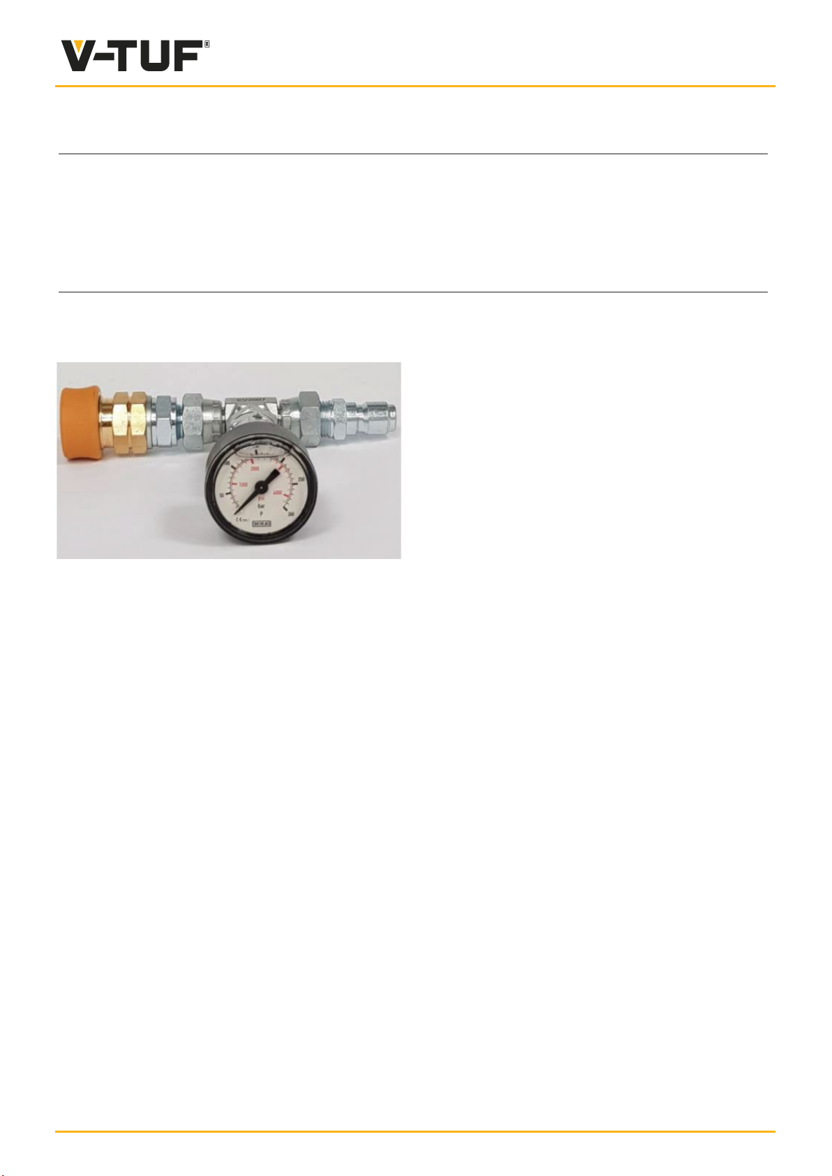
Connect the suction hose to the inlet coupling.
Connect the outlet hose to the outlet coupling.
Connect the other end of the suction hose to
the water tap.
Check that the electric plug has all the required
characteristics and the proper differential protection
than, connect if into the electrical socket.
NOTE: if is possible, do not use electrical extensions.
WARNING: the electrical feeding network must be equipped with an high sensibility
differential switch with an interference thresold id equal to 30 mA.
The machine must be earthed at a contact voltage resistant value not over 25 V.
The machine must be installed so that the pipings connot be damaged by people or things.
The machine should be placed out of passage ways and in order to avoid mechanical stress
and damages.
CHECKS BEFORE USE
Before the use, check that all the parts was fitted up
and that the installation was checked by skilled personnel.
Check that are gasoil in the apposite tank,
if not, fill up.
Turn on the water lap.
Check that the thermostat is in "O” °C position.
Start the machine acting on the apposite (ON/OFF) burner switch and wait for 30 sec. to
obtain the filling of the gasoil pump, act on the thermostat knob and put the temperature
selector at 90° C for almost 30 sec. than, select tha water working temperature acting on
the same knob.
When the request temperature is reached, the burner automatically stop and start again
every time the temperature reachees.
At the end of the work, put the thermostat knob at ("0") 0° C position and wait for the
water to be cold.
Act on the (ON/OFF) burner switch to stop the machine then, close the water tap.
H O outlet
2H O inlet
2
Burner ON/OFF switch
Thermostat knob
USE

9
USE
USE IN ENCLOSED AREAS
In case the machine is placed in an enclosed area,
You have to install the chimney adapter our code: 5000030.
We suggest the use of a chimney as illustrated in the picture.
WARNING: the chimney (2) diameter (Z)
should not be inferior than the adapter (1).
USE IN WINDY PLACE
In case the machine is placed in a windy place, You have to install the chimney
adapter our code: 5000030.
This precautionary measure can avoid damages to Your machine.

10
V-TUF STEAM OPERATION WITH HOT BOX
With the aid of the V-TUF Super-heated steam performance kit. You can customise your
“hotbox” for many demanding & specialised cleaning processes, including historical restoration
& renovation projects.
SUPER HEATED STEAM PERFORMANCE KIT:
Set up the PRESSURE GAUGE 0 to 300BAR CALIBRATING KIT MSQ - C6.030KIT
below on the cold side of the HOT BOX. Remove the gauge kit once calibration.
To select the ultimate pressure suited to the surface you are cleaning, and make sure
that you have the correct nozzle size (see below) to suit that pressure.
Nozzle size: 09 - Pressure: 30 BAR
Nozzle size: 08 - Pressure: 40 BAR
Nozzle size: 07 – Pressure: 50 BAR
Nozzle size: 065 – Pressure: 60 BAR
Nozzle size: 06 – Pressure: 70 BAR
Nozzle size: 05 – Pressure: 100 BAR
Nozzle size: 04 - Pressure: 145 BAR
Remember: Please select the best jet spray angle too (0 degree; 15 degrees; 25 degrees; 40
degrees).
0 degree jets: https://www.v-tuf.co.uk/spares-accessories/triggers-lances-nozzles/nozzles
holders/fan-nozzles/00-pencil-jet-nozzle
15 degree jets: https://www.v-tuf.co.uk/spares-accessories/triggers-lances-nozzles/nozzles
holders/fan-nozzles/150-fan-nozzle
25 degree jets: https://www.v-tuf.co.uk/spares-accessories/triggers-lances-nozzles/nozzles
holders/fan-nozzles/250-fan-nozzle
40 degree jets: https://www.v-tuf.co.uk/spares-accessories/triggers-lances-nozzles/nozzles
holders/fan-nozzles/400-fan-nozzle
These nozzles are calibrated with the standard hot box fuel injector size of 1.35 80H

11
To maintain efficient and effective cleaning above 100 deg C with your V-TUF HOTBOX
there are certain very important settings that must be in place:
1. For optimal cleaning effectiveness, turn the pressure adjustment knob
(anti-clockwise – to lower pressure) on your V-TUF pressure washer.
2. Calibrate the pressure (before switching the HOT BOX on) to the correct
nozzle size as shown in the list on the previous page.
Picture 1
2. Please the jet into the end of the spray lance and then check your calibration on
cold. Once you are happy with this then turn the thermostat of your HOTBOX on highest
temperature (clock-wise – see below)
Picture 2
Important points:
1. Run machine on this setting and you will notice the hot water will start steaming.
2. Proceed with cleaning.
3. Please note when the unit is very hot, the trigger can only be closed off for very
short periods.
4. If you wish to take a break – you must turn the thermostat knob (picture 2)
anti-clockwise to 0 degC and run the water cool. Do this every time!

12
SAFETY RULES
Do not consent intervention on the machine at not authorized personnel.
Do not carry out any intervention without preventive authorization.
Before every check and/or maintenance work, check that the
machine
Do not put the limbs into the openings of the machine parts
without the aid of suitable guards.
Do not aligne the holes with the fingers but only using the suitable centering fools.
Never use gasoline, solvents or other flammable liquid to cleane; instead apply to the
commercialized detergents, authorized, unflammables and untoxic.
Using compressed air for clean or dry parts of the machine,
protect the eyes with goggles equipped with side guards
and limit the air working pressure at max. 1,9 bar.
Every day keep clean and in good order the machine.
Immediately replace each notice, warning or instruction
plate that is not readable or missing
WARNING: a poorly adjustment
of the burner, increases the
fuel consumption and causes
environmental pollution.
WARNING: if the machine remain for a long time idle, before using it for any
cleaning operation, we suggest to let the water flow in the coil for some time,
fill it comes out clean.
MAINTENANCE
Maintain in efficency the equipment it means to ensure more reliability and a longer life;
please follow simple check on a regular basis.

13
BURNER MAINTENANCE
The burner installed on our high pressure cleaner, runs only with gasoil.
Periodically check and clean the filters and the fuel nozzle, we
recommend the replacement of the same every 400 working hours.
BODY AND TANK WORK MAINTENANCE
Wash the machine only with neutral surface-active products and water in order to eliminate
corrosive agents (such as salt, sand, etc.); accurately dry so as to thoroughly eliminate
any patches of water.
If trace of dirt persist, we recommend the use of specific products following the instructions
provided by the manufacturer.
WARNING: DO NOT USE products containing aromatic solvents, methanol
or hydrocarbon.
HYDRAULIC SYSTEM
Periodically check that all the system parts are correctly tights
and that are not leakages.
COIL
If the coil is covered with sooth, You should check the burner at the
Customer Service Centre.
AIR FLOW ADJUSTMENT
On 60 Hz models is installed an air flow adjusting blade; this
device placed between the fan and the boiler is adjusted by
the manufacturer but acting on the apposite nut, the slope
will be changed for allow a small or a greater air flow.
ELECTRODES SETTING
To obtain the best performances of the machine, check that the starting electrodes are
always placed as showns in picture.
WARNING: for repair, special maintenance operations or for setting up of the
machine, apply to the Customer Service Centre or to the authorized technicians
only.

13
The water does not reach
working temperature.
Damaged thermostat.
Thermostat adjusted too low.
Scale in the hydraulic system.
Sooted boiler.
Water in the gasoil tank.
Incorrect gasoil pressure.
Electrodes improperly
positioned.
Fuel nozzle dirty.
Fuel nozzle worm out.
Heating coil blocked by soot.
Gasoil pump dirty.
Gasoil solenoid valve not operating.
Gasoil tank empty
Water in the gasoil tank.
Fluxostath damaged.
Starting transformer damaged.
Rotation of the starting
electrodes.
Gasoil nozzle dirty.
Gasoil nozzle damaged.
Gasoil pump damaged.
Gasoil solenoid valve
damaged.
No current.
Replace.
Place the thermostat at the
required temperature.
Contact the Maintenance
Service.
Contact the maintenance
Service.
Completely drain the gasoil
tank than, fill up with clean
gasoil.
Turn the adjusting screw
until obtaining aprox. 10
bar; contact the Maintenance
Service.
Adjust the distance between
the electrodes;contact the
Maintenance Service.
Clean the fuel nozzle.
Replace the fuel nozzle.
Clean the heating coil.
Disassemble the pump and
clean the filter; contact the
Mainenance Service.
Replace the solenoid valve.
Fil up the gasoil tank.
Completely drain the gasoil
tank and fill up with clean
gasoil
Replace the fluxostath.
Replace the transformer.
Set the electrodes back to
their proper position; contact
the Maintenance Service.
Clean the nozzle.
Replace the nozzle.
Replace the gasoil pump.
Replace the gasoil solenoid
valve.
Check if the plug is in the
socket and if there is current
in the network.
The boiler is smoking
The burner cut out during
operation
The motor does not start

14
SYSTEM PLANS
WIRING DIAGRAM
I
MP
TA
F
E.V.
T
M
Switch
Burner motor
Transformator
Fluxostath
Gasoil solenoid valve
Thermostat
Ground

15
Our Company reserves the right to introduce at any time, eventual changes
for technical or commercial reasons, therefore informations, descriptions and
illustrations contained in this publication, are updated until their approval for
the printing.
WARNING: the graphic illustration of the part, can be different from the detail
mounted on the machine, only the code number on the spare parts catalogue,
determinates the spare part validity.

16
This manual suits for next models
1
Table of contents
Popular Portable Generator manuals by other brands

Generac Power Systems
Generac Power Systems XG 6500 Watt Series owner's manual

Agilent Technologies
Agilent Technologies 75000 Series C Service manual

morse
morse GCRS-40-40 T4F product manual

Jackery
Jackery Explorer 1500 user guide

Extron electronics
Extron electronics VTG 300R brochure

Champion Power Equipment
Champion Power Equipment 100463 Operator's manual