OPERATION
Initial Pre-Start Inspection
Before starting the unit for the first time, the following
inspections and checks are recommended:
a. Clear the site area of any loose parts, connections,
or foreign materials such as cut off tie wrap ends,
scrap insulating tape, tools, hardware, etc.
b. Insure that the set turns freely. Bar the set over by
hand for at least 2 revolutions to be sure that there
is no interference. Do not use the generator’s fan as
a fulcrum to bar over the set. If the generator rotor
seems to bind, check for clearance in the generator
and exciter air gap.
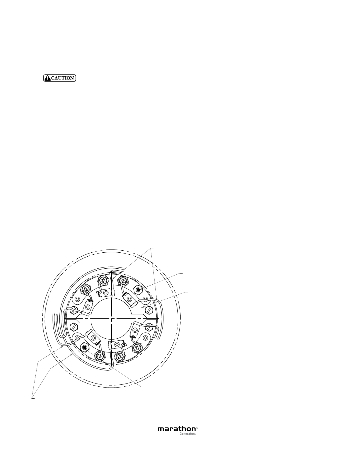
c. Check all wiring against the proper connection
diagrams, and insure that all connections and
terminations are tight and properly insulated
PANCAKE GENERATORS MAY HAVE VOLTAGE
PRESENT AT THEIR LEAD TERMINALS WHEN THE
SHAFT IS ROTATING. DO NOT PERMIT OPERATION
OF THE UNIT UNTIL ALL LEADS HAVE BEEN
CONNECTED AND INSULATED. FAILURE TO DO THIS
MAY RESULT IN PERSONAL INJURY OR EQUIPMENT
DAMAGE.
d. Insure that all equipment is properly grounded
(earthed).
e. Inspect for any remaining packing materials, and
remove any loose debris, building materials, rags,
etc., which could be drawn into the generator.
f. Check all fasteners for tightness.
g. Check all access plates, covers, screens, and
guards. If they have been removed for assembly or
inspection, reinstall and check for security.
h. Review all prime mover manufacturer’s pre start-up
instructions, and insure that all recommended steps
and procedures have been followed.
i. Remove any paint masking material from the
generator nameplate and warning/caution decals.
Initial Start-Up
The following procedure should be followed for starting-
up the generator set for the first time:
a. The generator output must be disconnected from
the load. Be sure that the main circuit breaker or
fused disconnect is in the open position.
b. Open the input power to the automatic voltage
regulator (AVR). Remove the fuse or disconnect and
insulate one of the AVR input power leads (see AVR
manual)
c. Insure that all prime mover manufacturer’s pre-start-
up and start-up procedures have been followed.
d. Start the prime mover, and adjust it for proper speed
(frequency). (See generator nameplate.)
e. The purpose of this initial test with the AVR out of
the circuit is to detect any wiring mistakes without
exposing the unit to undue risk. Check all Line-
to-Line and Line-to-Neutral voltages for balanced
voltage. At this point, with the AVR de-energized,
the residual voltage should be about 10% to 25% of
rated value. If voltages are unbalanced, shut down
the equipment and check for improper wiring. Re-
start the set, and again check for voltage balance. If
the problem persists, consult the factory. If everything
checks good, shut down the set and reconnect the
AVR. It is recommended that the residual voltage,
together with driver rpm, be recorded for use as a
future troubleshooting benchmark
f. Start the set and adjust the terminal voltage to
the desired value by means of the AVR voltage
adjustment device. If the AVR is equipped with a
stability adjust, follow the instructions in the AVR
manual to adjust the stability. Again, check all line-
to-line and line-to-neutral voltages for balance.
It is recommended practice to record the no load
excitation (DC voltage across F+ and F-) together
with line-to-line voltage and driver rpm as a bench
mark for future troubleshooting
THIS PROCEDURE MUST BE CONDUCTED BY
QUALIFIED ELECTRICAL PERSONNEL. LETHAL
VOLTAGE MAY WELL BE PRESENT AT BOTH. THE
GENERATOR AND VOLTAGE REGULATOR TERMINALS
DURING THIS PROCEDURE. CAUTION MUST BE
EXERCISED NOT TO COME INTO PERSONAL
CONTACT WITH LIVE TERMINALS, LINKS, OR STUDS.
SERIOUS INJURY OR DEATH COULD RESULT.
g. Close the main circuit breaker to the load. If the unit
is equipped with space heaters, insure that they are
turned off.
h. Monitor the generator output current to verify that it
is at or below nameplate value.
i. Check generator frequency (speed) under load.
Adjust as necessary. (Refer to prime mover/governor
manuals)
5