Vaillant VR 34 User manual

Publisher/manufacturer
INT
VR 34
0020017897

2
Contents
Installation instructions VR34 0020287799_00
Contents
cs - Návod k instalaci...............................................................3
da - Installationsvejledning .....................................................7
de - Installationsanleitung .....................................................11
en - Installation instructions .................................................15
es - Instrucciones de instalación..........................................19
fr - Notice d’installation .........................................................23
hr - Upute za instaliranje .......................................................27
hu - Szerelési útmutató ..........................................................31
it - Instruzioni per l‘installazione ..........................................35
nl - Installatiehandleiding ......................................................39
no - Installasjonsveiledning ..................................................43
pl - Instrukcja instalacji .........................................................47
ro - Paigaldusjuhend ..............................................................51
ru - Руководство по монтажу ..............................................55
sk - Návod na inštaláciu ........................................................59
sl - Navodila za namestitev ...................................................63
sr - Įrengimo instrukcija ........................................................67
sv - Installationsanvisning ....................................................71
tr - Montaj kılavuzu .................................................................75
uk - Посібник зі встановлення ............................................79
zh - 安装说明 ............................................................................83
Country specifics ...................................................................87
Figures...................................................................................101

3Návod k instalaci VR34 0020287799_00
Bezpečnost
cs
cs - Návod k instalaci
1 Bezpečnost
1.1 Použití v souladu s určením
Při neodborném používání nebo použití v rozporu s určením
může dojít k poškození výrobku a k jiným věcným škodám.
Výrobek umožňuje připojit cizí regulátor s výstupem 0–10 V na
zdroj tepla eBUS Vaillant.
Použití v souladu s určením zahrnuje:
>dodržování přiložených návodů k obsluze, instalaci a údržbě
výrobku a všech dalších součástí systému
Jiné použití, než je popsáno v tomto návodu, nebo použití,
které přesahuje zde popsaný účel, je považováno za použití v
rozporu s určením. Každé přímé komerční nebo průmyslové
použití je také v rozporu s určením.
aa

4
Popis výrobku
Návod k instalaci VR34 0020287799_00
2 Popis výrobku
2.1 Rozsah dodávky
1 Obr. 1.1 Deska plošných spojů rozhraní
2 Zástrčka X1 s kabelovým můstkem (způsob regulace)
3 Kabelová průchodka s odlehčovací sponou
4 Propojovací kabel X32 deska plošných spojů rozhraní k
desce plošných spojů zdroje tepla
5 Zástrčka X14 s připojovacími svorkami cizího regulátoru a
relé
2.2 Přehled výrobků
1 Obr. 1.2 Pozice X1 (způsob regulace):
– zasunuto (stav při dodání): požadovaná hodnota
výstupní teploty
– nezasunuto: požadovaná hodnota výkonu
2 Pozice X32 přípojka ke zdroji tepla
3 Stavová světelná dioda (zelená)
4 Připojovací svorka cizího regulátoru a relé
2.3 Označení CE
Označením CE se dokládá, že výrobky podle typového štítku
splňují základní požadavky příslušných směrnic.
Prohlášení o shodě je k nahlédnutí u výrobce.
3 Montáž a instalace
Elektroinstalaci smí provádět pouze specializovaný elektrikář.
Dodržujte všechny návody k výrobku a všechny příslušné
směrnice, normy, zákony a ostatní předpisy.
>Dodržujte návod k instalaci zdroje tepla.
3.1 Předpisy (směrnice, zákony, vyhlášky a
normy)
>Dodržujte vnitrostátní předpisy, normy, směrnice, nařízení a
zákony.

5Návod k instalaci VR34 0020287799_00
Montáž a instalace
cs
3.2 Stanovení způsobu regulace
Výrobek může poskytovat buď požadovanou hodnotu výkonu,
nebo požadovanou hodnotu výstupní teploty. Ve stavu při
dodání (zástrčka X1 zasunutá) se poskytuje požadovaná hod-
nota výstupní teploty.
>Obr. 1.3 Pro poskytování požadované hodnoty výkonu
vytáhněte zástrčku X1 s kabelovým můstkem z pozice X1.
Maximální a minimální výstupní teplota závisí na nastavení na
zdroji tepla. Doporučujeme nastavit požadovanou výstupní tep-
lotu zdroje tepla na maximum.
3.3 Nasazení propojovacího kabelu
>Obr. 1.4 Nasaďte propojovací kabel do pozice X32 desky
plošných spojů rozhraní.
3.4 Připojení cizího regulátoru k výrobku
>Obr. 1.5 Připojte cizí regulátor k zástrčce pro pozici X14.
– Řídicí signál cizí regulátor: svorka I
– Zemnicí vodič: svorka
>Dodržujte polaritu přípojek.
>Podle typu spínací skříňky použijte kabelovou průchodku a/
nebo odlehčovací spony.
3.5 Montáž výrobku
>Otevřete spínací skříňku zdroje tepla.
>Obr. 1.7a+b Výrobek zasuňte do vedení ve skříňce elektro-
niky.

6
Recyklace a likvidace
Návod k instalaci VR34 0020287799_00
3.6 Připojení výrobku ke zdroji tepla
>Obr. 1.8 Spojovací kabel zastrčte na zdroji tepla do pozice
X32.
3.7 Připojení relé k výrobku (volitelně)
>Obr. 1.6 V případě potřeby připojte relé na výrobek v pozici
X14 an.
– Spínací signál relé: svorka F
– Vedení nízkého napětí relé: svorka 24V
3.8 Ukončení instalace
>Uveďte výrobek do provozu.
>Nastavte požadovanou výstupní teplotu na maximum.
>Zkontrolujte instalaci rozhraní.
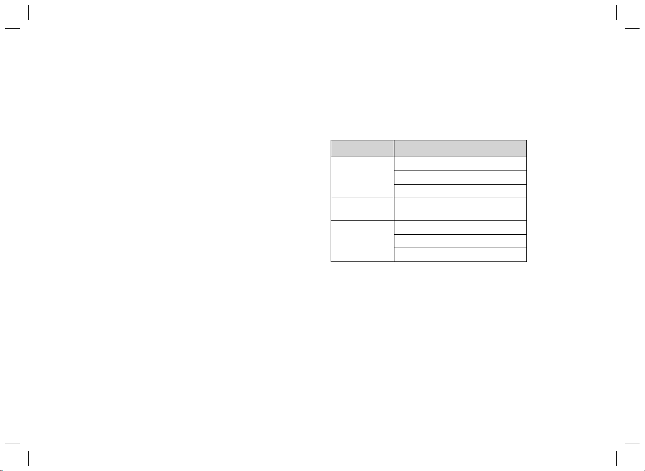
Stav Význam
Svítí trvale Není připojen cizí regulátor
Napětí < 0,5V
Žádný požadavek na vytápění
Rychle bliká Žádné spojení eBus ke zdroji tepla
Svítí s krátkými přerušeními Normální funkce
Napětí > 1,5V
Aktivní požadavek na vytápění
4 Recyklace a likvidace
Likvidace obalu
>Obal odborně zlikvidujte.
>Dodržujte všechny příslušné předpisy.

7Installationsvejledning VR34 0020287799_00
Sikkerhed
da
da - Installationsvejledning
1 Sikkerhed
1.1 Korrekt anvendelse
Enheden og andre materielle værdier kan forringes ved ukor-
rekt eller forkert anvendelse af produktet.
Med produktet er det muligt at tilslutte en ekstern styring med
0-10 V udgang til en Vaillant eBUS-varmegiver.
Korrekt anvendelse omfatter:
>overholdelse af de medfølgende betjenings-, installations-
og vedligeholdelsesvejledninger til produktet samt alle
øvrige anlægskomponenter
Anden anvendelse end den, der er beskrevet i denne vejled-
ning, og anvendelse, der går ud over den her beskrevne, er
forkert. Forkert anvendelse omfatter også enhver umiddelbar
kommerciel og industriel anvendelse.
aa

8
Produktbeskrivelse
Installationsvejledning VR34 0020287799_00
2 Produktbeskrivelse
2.1 Leveringsomfang
1 Fig. 1.1 Brugerflade-printplade
2 Stik X1 med kabelbro (styringsart)
3 Kabelgennemføring med trækaflastning
4 Forbindelseskabel X32 brugerfladeprintplade til printplade
varmegiver
5 Stik X14 med tilslutningsklemmer ekstern styring og relæ
2.2 Produktoversigt
1 Fig. 1.2 Stikplads X1 (styringsart):
– Isat (leveringstilstand): Nominel fremløbstemperatur-
værdi
– Ikke isat: Nominel effektværdi
2 Stikplads X32 tilslutning til varmegiver
3 Status lysdiode (grøn)
4 Tilslutningsklemme ekstern styring og relæ
2.3 CE-mærkning
CE-mærkningen dokumenterer, at produkterne i henhold til
typeskiltet overholder de grundlæggende krav i de relevante
direktiver.
Overensstemmelseserklæringen foreligger hos producenten.

9Installationsvejledning VR34 0020287799_00
Montering og installation
da
3 Montering og installation
Elinstallationen må kun foretages af en elektriker. Vær
opmærksom på alle produktledsagende vejledninger og alle
gældende retningslinjer, normer, love og andre forskrifter.
>Vær opmærksom på installationsvejledningen til varmegive-
ren.
3.1 Forskrifter (direktiver, love, standarder)
>Overhold de gældende forskrifter, normer, retningslinjer, for-
ordninger og love.
3.2 Fastlæggelse af styringsart
Produktet kan enten fastsætte en nominel effektværdi eller en
nominel fremløbstemperaturværdi. I leveringstilstand (stik X1
påsat) fastsættes en nominel fremløbstemperaturværdi.
>Fig. 1.3 Træk stik X1 med kabelbroen ud af stikplads X1 for
at fastsætte en nominel effektværdi.
Den maksimale og den minimale fremløbstemperatur afhænger
af varmegiverens indstilling. Vi anbefaler at indstille varmegive-
rens nominelle fremløbstemperatur til maks.
3.3 Isætning af forbindelseskabel
>Fig. 1.4 Isæt forbindelseskablet på brugerflade-printpladens
stikplads X32.
3.4 Tilslutning af ekstern styring til produktet
>Fig. 1.5 Tilslut den eksterne styring til stikket for stikplads
X14.
– Styresignal ekstern styring: Klemme I
– Jordledning: Klemme
>Læg mærke til tilslutningernes polaritet.
>Brug kabelgennemføringen og/eller trækaflastningerne i kon-
trolboksen, afhængigt af kontrolbokstype.
3.5 Montering af produktet
>Åbn varmegiverens kontrolboks.
>Fig. 1.7a+b Stik produktet ind i føringerne i kontrolboksen.

10
Genbrug og bortskaffelse
Installationsvejledning VR34 0020287799_00
3.6 Tilslutning af produkt til varmegiver
>Fig. 1.8 Isæt forbindelseskablet på varmegiveren på stik-
plads X32.
3.7 Tilslutning af relæ til produktet (valgfrit)
>Fig. 1.6 Slut i givet fald et relæ til produktet på stikplads
X14.
– Skiftesignal relæ: Klemme F
– Lavspændingsledning relæ: Klemme 24V
3.8 Afslutning af installationen
>Start produktet.
>Indstil den nominelle fremløbstemperatur til maks.
>Kontrollér installationen af brugerfladen.
Status Betydning
Lyser perma-
nent
Ingen ekstern styring tilsluttet
Spænding < 0,5V
Ingen varmeanmodning
Hurtigt blin-
kende
Ingen eBUS-forbindelse til varme-
giveren
Lyser med
korte afbrydel-
ser
Normal funktion
Spænding > 1,5V
Varmekrav til stede
4 Genbrug og bortskaffelse
Bortskaffelse af emballagen
>Bortskaf emballagen i overensstemmelse med reglerne.
>Følg alle relevante forskrifter.

11Installationsanleitung VR34 0020287799_00
Sicherheit
de
de - Installationsanleitung
1 Sicherheit
1.1 Bestimmungsgemäße Verwendung
Bei unsachgemäßer oder nicht bestimmungsgemäßer Verwen-
dung können Beeinträchtigungen des Produkts und anderer
Sachwerte entstehen. Das Produkt ermöglicht es, einen Frem-
dregler mit 0-10 V Ausgang an einen Vaillant eBUS-Wärmeer-
zeuger anzuschließen.
Die bestimmungsgemäße Verwendung beinhaltet:
>das Beachten der beiliegenden Betriebs-, Installationsund
Wartungsanleitungen des Produkts sowie aller weiteren
Komponenten der Anlage
Eine andere Verwendung als die in der vorliegenden Anleitung
beschriebene oder eine Verwendung, die über die hier
beschriebene hinausgeht, gilt als nicht bestimmungsgemäß.
Nicht bestimmungsgemäß ist auch jede unmittelbare kommer-
zielle und industrielle Verwendung.
aa

12
Produktbeschreibung
Installationsanleitung VR34 0020287799_00
2 Produktbeschreibung
2.1 Lieferumfang
1 Abb. 1.1 Schnittstellen-Leiterplatte
2 Stecker X1 mit Kabelbrücke (Regelungsart)
3 Kabeldurchführung mit Zugentlastung
4 Verbindungskabel X32 Schnittstellen-Leiterplatte zu Lei-
terplatte Wärmeerzeuger
5 Stecker X14 mit Anschlussklemmen Fremdregler und
Relais
2.2 Produktübersicht
1 Abb. 1.2 Steckplatz X1 (Regelungsart):
– gesteckt (Auslieferungszustand): Vorlauftemperatur-
sollwert
– nicht gesteckt: Leistungssollwert
2 Steckplatz X32 Anschluss an Wärmeerzeuger
3 Status LED (grün)
4 Anschlussklemme Fremdregler und Relais
2.3 CE-Kennzeichnung
Mit der CE-Kennzeichnung wird dokumentiert, dass die Pro-
dukte gemäß dem Typenschild die grundlegenden Anforderun-
gen der einschlägigen Richtlinien erfüllen.
Die Konformitätserklärung kann beim Hersteller eingesehen
werden.

13Installationsanleitung VR34 0020287799_00
Montage und Installation
de
3 Montage und Installation
Die Elektroinstallation darf nur von einer Elektrofachkraft durch-
geführt werden. Beachten Sie alle produktbegleitenden Anlei-
tungen und alle einschlägigen Richtlinien, Normen, Gesetze
und anderen Vorschriften.
>Beachten Sie die Installationsanleitung des Wärmeerzeu-
gers.
3.1 Vorschriften (Richtlinien, Gesetze, Normen)
>Beachten Sie die nationalen Vorschriften, Normen, Richtli-
nien, Verordnungen und Gesetze.
3.2 Regelungsart festlegen
Das Produkt kann entweder einen Leistungssollwert oder einen
Vorlauftemperatursollwert vorgeben. Im Auslieferungszustand
(Stecker X1 aufgesteckt) wird ein Vorlauftemperatursollwert
vorgegeben.
>Abb. 1.3 Ziehen Sie zur Vorgabe eines Leistungssollwerts
den Stecker X1 mit der Kabelbrücke vom Steckplatz X1 ab.
Die maximale und die minimale Vorlauftemperatur hängen von
der Einstellung am Wärmeerzeuger ab. Wir empfehlen die Vor-
laufsolltemperatur des Wärmeerzeugers auf max. einzustellen.
3.3 Verbindungskabel aufstecken
>Abb. 1.4 Stecken Sie das Verbindungskabel auf den Steck-
platz X32 der Schnittstellen-Leiterplatte.
3.4 Fremdregler an das Produkt anschließen
>Abb. 1.5 Schließen Sie den Fremdregler an den Stecker für
den Steckplatz X14 an.
– Steuersignal Fremdregler: Klemme I
– Masseleitung: Klemme
>Beachten Sie die Polung der Anschlüsse.
>Nutzen Sie je nach Schaltkastentyp die Kabeldurchführung
und/oder die Zugentlastungen im Schaltkasten.
3.5 Produkt montieren
>Öffnen Sie den Schaltkasten des Wärmeerzeugers.
>Abb. 1.7a+b Stecken Sie das Produkt in die Führungen im
Schaltkasten.

14
Recycling und Entsorgung
Installationsanleitung VR34 0020287799_00
3.6 Produkt an Wärmeerzeuger anschließen
>Abb. 1.8 Stecken Sie das Verbindungskabel am Wärmeer-
zeuger auf Steckplatz X32.
3.7 Relais an das Produkt anschließen (optional)
>Abb. 1.6 Schließen Sie ggf. ein Relais an das Produkt am
Steckplatz X14 an.
– Schaltsignal Relais: Klemme F
– Niederspannungsleitung Relais: Klemme 24V
3.8 Installation abschließen
>Nehmen Sie das Produkt in Betrieb.
>Stellen Sie die Vorlaufsolltemperatur auf maximal ein.
>Prüfen Sie die Installation der Schnittstelle.
Status Bedeutung
leuchtet permanent kein Fremdregler angeschlossen
Spannung < 0,5V
Keine Heizanforderung
Schnell blinkend Keine eBus-Verbindung zum Wärmeerzeuger
leuchtet mit kurzen
Unterbrechungen
Normalfunktion
Spannung > 1,5V
Heizanforderung vorhanden
4 Recycling und Entsorgung
Verpackung entsorgen
>Entsorgen Sie die Verpackung ordnungsgemäß.
>Beachten Sie alle relevanten Vorschriften.

15Installation instructions VR34 0020287799_00
Safety
en
en - Installation instructions
1 Safety
1.1 Intended use
In the event of inappropriate or improper use, damage to the
product and other property may arise.
The product enables a thirdparty control with 0–10 V output to
be connected to a Vaillant eBUS heat generator.
Intended use includes the following:
>observance of accompanying operating, installation and
maintenance instructions for the product and any other sys-
tem components
Any other use that is not specified in these instructions, or use
beyond that specified in this document, shall be considered
improper use. Any direct commercial or industrial use is also
deemed to be improper.
aa

16
Product description
Installation instructions VR34 0020287799_00
2 Product description
2.1 Scope of delivery
1 Fig. 1.1 Interface PCB
2 Plug X1 with cable bridge (control type)
3 Grommet with strain relief
4 Connection cable X32, interface PCB to heat generator
PCB
5 Plug X14 with connection terminals for third-party control
and relay
2.2 Product overview
1 Fig. 1.2 Slot X1 (control type):
– Plugged (as supplied): Target flow temperature value
– Not plugged: Target output value
2 Slot X32 connection to the heat generator
3 Status LED (green)
4 Connection terminal for third-party control and relay
2.3 CE marking
The CE marking shows that the products comply with the basic
requirements of the applicable directives as stated on the data
plate.
The declaration of conformity can be viewed at the manufactur-
er‘s site.

17Installation instructions VR34 0020287799_00
Assembly and installation
en
3 Assembly and installation
Only qualified electricians may carry out the electrical installa-
tion. Observe the instructions that are supplied with the product
and all applicable directives, standards, laws and other regula-
tions.
>Observe the installation instructions for the heat generator.
3.1 Regulations (directives, laws, standards)
>Observe the national regulations, standards, directives, ordi-
nances and laws.
3.2 Defining the control type
The product can specify either a target output value or a target
flow temperature value. A target flow temperature value is
specified in the as-supplied state (plug X1 plugged in).
>Fig. 1.3 To specify a target output value, remove plug X1
with the cable bridge from slot X1.
The maximum and minimum flow temperature depend on the
setting on the heat generator. We recommend setting the heat
generator‘s target flow temperature to the maximum.
3.3 Plugging in the connection cable
>Fig. 1.4 Plug the connection cable into slot X32 on the inter-
face PCB.
3.4 Connecting a third-party control to the
product
>Fig. 1.5 Connect the third-party control to the plug for slot
X14.
– Control signal for third-party control: Terminal I
– Earth line: Terminal
>Observe the polarity of the connections.
>Depending on the type of electronics box, use the grommet
and/or the strain reliefs in the electronics box.
3.5 Installing the product
>Open the heat generator‘s electronics box.
>Fig. 1.7a+b Insert the product into the guides in the electron-
ics box.

18
Recycling and disposal
Installation instructions VR34 0020287799_00
3.6 Connecting the product to the heat generator
>Fig. 1.8 Plug the connection cable on the heat generator
into slot X32.
3.7 Connecting the relay to the product (optional)
>Fig. 1.6 If required, connect a relay to the product at slot
X14.
– Relay switch signal: Terminal F
– Low-voltage line relay: Terminal 24 V
3.8 Completing installation
>Start up the product.
>Set the target flow temperature to maximum.
>Check the installation of the interface.
Status Meaning
Lights up permanently No third-party control connected
Voltage: < 0,5V
No heat demand
Flashing rapidlykend No eBUS connection to the heat generator
Lights up with brief
interruptions
Normal function
Voltage: > 1.5 V
Heat demand present
4 Recycling and disposal
Disposing of the packaging
>Dispose of the packaging correctly.
>Observe all relevant regulations.

19Instrucciones de instalación VR34 0020287799_00
Seguridad
es
es - Instrucciones de instalación
1 Seguridad
1.1 Utilización adecuada
Su uso incorrecto o utilización inadecuada puede provocar
daños en el producto u otros bienes materiales.
El producto permite conectar un regulador externo con salida
0-10 V a un generador de calor eBUS de Vaillant.
La utilización adecuada implica:
>Tenga en cuenta las instrucciones de funcionamiento, insta-
lación y mantenimiento del producto y de todos los demás
componentes de la instalación
Una utilización que no se corresponda con o que vaya más
allá de lo descrito en las presentes instrucciones se considera
inadecuada. También se considera inadecuada cualquier utili-
zación directamente comercial o industrial.
aa

20
Descripción del aparato
Instrucciones de instalación VR34 0020287799_00
2 Descripción del aparato
2.1 Volumen de suministro
1 Fig. 1.1 Placa de circuitos impresos de interfaces
2 Conector X1 con canal para cables (tipo de regulación)
3 Conducto de cables con descarga de tracción
4 Cable de unión X32 de la placa de circuitos impresos de
interfaces a la placa de circuitos impresos del generador
de calor
5 Conector X14 con bornes de conexión del regulador
externo y relé
2.2 Vista general del aparato
1 Fig. 1.2 Ranura X1 (tipo de regulación):
– ocupada (estado de entrega): valor nominal de la tem-
peratura de ida
– no ocupada: valor nominal de potencia
2 Ranura X32 conexión al generador de calor
3 LED de estado (verde)
4 Borne de conexión del regulador externo y relé
2.3 Homologación CE
Con la homologación CE se certifica que los aparatos cumplen
los requisitos básicos de las directivas aplicables conforme
figura en la placa de características.
Puede solicitar la declaración de conformidad al fabricante.
Other manuals for VR 34
2
Table of contents
Languages: