manuals.online logo
Brands
  1. Home
  2. •
  3. Brands
  4. •
  5. Vaillant
  6. •
  7. Boiler
  8. •
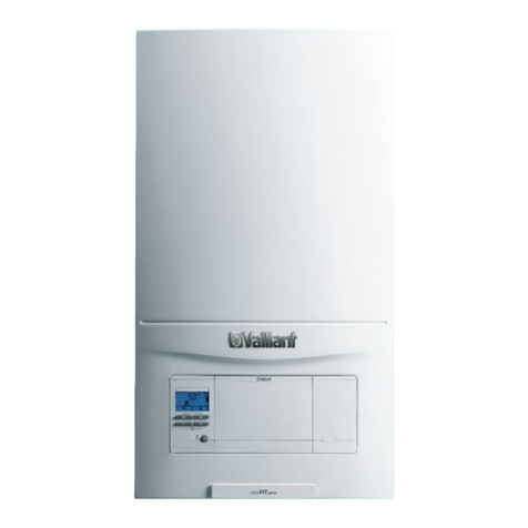
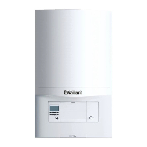
  9. Vaillant ecoTEC plus VU Series User manual

Vaillant ecoTEC plus VU Series User manual

en Installation and maintenance instructions
ecoTEC plus
VU../VUW..
0020308118_05 - 31.05.2023
2Installation and maintenance instructions 0020308118_05
Installation and maintenance
instructions
Contents
1 Safety .................................................................... 4
1.1 Intended use .......................................................... 4
1.2 Qualification ........................................................... 4
1.3 General safety information .................................... 4
1.4 Regulations (directives, laws, standards) .............. 7
1.5 List of relevant standards for Great Britain and
Ireland.................................................................... 7
2 Guarantee and Customer Service...................... 8
3 Technical data...................................................... 9
4 Notes on the documentation ............................ 16
5 Product description........................................... 16
5.1 CE marking .......................................................... 16
5.2 UKCA mark.......................................................... 16
5.3 Hot Water Association ......................................... 16
5.4 Water Regulations Advisory Scheme .................. 16
5.5 Data plate ............................................................ 17
5.6 Serial number ...................................................... 17
5.7 Sitherm Pro™ technology.................................... 17
5.8 Display of the energy consumption, energy
yields and efficiencies.......................................... 17
5.9 Product design..................................................... 18
5.10 Design of the product's hydraulic block ............... 19
5.11 Safety Devices..................................................... 19
6 Set-up.................................................................. 19
6.1 Checking the scope of delivery............................ 19
6.2 Product dimensions ............................................. 20
6.3 Installation site ..................................................... 20
6.4 Minimum clearances............................................ 21
6.5 Compartment Ventilation ..................................... 21
6.6 Using the mounting template............................... 21
6.7 Wall-mounting the product................................... 21
7 Installation.......................................................... 21
7.1 Prerequisites........................................................ 21
7.2 Installing the air/flue pipe..................................... 23
7.3 Installing the gas connection ............................... 27
7.4 Installing the hot and cold water connection........ 28
7.5 Connecting the domestic hot water cylinder........ 28
7.6 Installing the heating flow and heating return ...... 28
7.7 Installing the heating flow and heating return ...... 28
7.8 Installing the condensate discharge .................... 28
7.9 Installing combined condensate and pressure
relief valve............................................................ 31
7.10 Electrical installation ............................................ 31
7.11 Installing the front casing..................................... 38
8 Operation............................................................ 38
8.1 Operating concept ............................................... 38
8.2 Calling up the installer level................................. 38
8.3 Calling up/setting diagnostics codes ................... 38
8.4 Running a check programme .............................. 38
8.5 Carrying out the actuator test .............................. 39
8.6 Calling up the data overview ............................... 39
8.7 Calling up status codes........................................ 39
8.8 Exiting the menu level.......................................... 39
8.9 Running the chimney sweep mode
(combustion analysis).......................................... 39
8.10 Switching on the button lock (Advanced Key
Lock) .................................................................... 39
9 Start-up ............................................................... 39
9.1 Pre-Commissioning checklist .............................. 39
9.2 Carrying out the initial start-up............................. 40
9.3 Checking and treating the heating water/filling
and supplementary water .................................... 40
9.4 Deactivating standby mode ................................. 41
9.5 Running through the installation assistant........... 41
9.6 Check programmes and actuator tests................ 42
9.7 Guaranteeing the system pressure ..................... 42
9.8 Flushing the heating installation for the first
time ("cold") ......................................................... 42
9.9 Filling the heating installation .............................. 43
9.10 Purging the heating installation ........................... 43
9.11 Filling and purging the domestic hot water
system ................................................................. 43
9.12 Filling the condensate siphon .............................. 44
9.13 Checking the gas settings ................................... 44
9.14 Thoroughly flushing the heating installation
("hot")................................................................... 47
9.15 Checking the heating mode................................. 48
9.16 Checking the domestic hot water generation ...... 48
9.17 Checking leak-tightness ...................................... 48
9.18 Converting the product to a different gas type..... 48
10 Adapting the unit to the installation ................ 48
10.1 Setting parameters .............................................. 48
10.2 Activating an additional component for the
multi-functional module........................................ 48
10.3 Adapting the heating mode settings .................... 49
10.4 Adapting the domestic hot water settings............ 53
10.5 Displaying the product information ...................... 53
11 Handing over to the end user........................... 53
12 Inspection and maintenance ............................ 54
12.1 Complete Service Interval Record section .......... 54
12.2 Using original seals.............................................. 54
12.3 Maintenance interval............................................ 54
12.4 Actuator test......................................................... 54
12.5 Inspection and maintenance................................ 54
12.6 Preparing the maintenance work......................... 54
12.7 Removing/installing the compact thermal
module ................................................................. 55
12.8 Cleaning/checking the components..................... 56
12.9 Draining the product ............................................ 58
12.10 Completing inspection and maintenance work .... 59
13 Troubleshooting ................................................ 59
13.1 Checking the data overview ................................ 59
13.2 Service messages ............................................... 59
13.3 Fault messages ................................................... 59
13.4 Limp home mode messages ............................... 59
0020308118_05 Installation and maintenance instructions 3
13.5 Resetting parameters to factory settings ............. 59
13.6 Eliminating faults in the product........................... 60
13.7 Replacing defective components......................... 60
14 Decommissioning.............................................. 68
14.1 Activate the standby mode .................................. 68
14.2 Temporarily decommissioning............................. 68
14.3 Permanently decommissioning............................ 68
15 Disposing of the packaging.............................. 68
Appendix ............................................................................ 69
A Tightening torques ............................................ 69
B Inspection and maintenance work................... 69
C Installer level ...................................................... 71
D Diagnostics codes ............................................. 72
E Status codes ...................................................... 79
F Fault codes......................................................... 80
G Check programmes ........................................... 91
H Actuator test....................................................... 91
I Maintenance codes............................................ 92
J Reversible limp home mode codes ................. 92
K Irreversible limp home mode codes ................ 92
L Wiring diagram................................................... 95
M Commissioning Checklist............................... 104
N Commissioning Flow Chart ............................ 108
Index ................................................................................. 109
4Installation and maintenance instructions 0020308118_05
1 Safety
1.1 Intended use
The product is intended as a heat generator
for sealed heating installations and for do-
mestic hot water generation.
Improper use of any kind is prohibited.
Intended use also includes the following:
–use of the product only in mobile homes
that are made, transported once and per-
manently situated in Great Britain and Ire-
land. After the transportation of the mo-
bile home to its destination the complete
product must be checked for leak-tightness
again
–validity of the product only for Great Britain
and Ireland and for the gas types in Great
Britain and Ireland as listed on the data
plate
–Installing and operating the product only
in conjunction with accessories for the
air/flue pipe which are listed in the other
applicable documents and comply with the
type of unit
–Using the product while observing the ac-
companying operating, installation and
maintenance instructions for the product
along with all other components of the in-
stallation
–Installing and setting up the product while
observing the product and system ap-
proval
–Observing all inspection and maintenance
conditions listed in the instructions
–Installing while observing the IP code
The following is classed as improper use:
–Using the product in vehicles, such
caravans. Units that are not classed as
vehicles are those that are installed in a
fixed and permanent location (known as
"fixed installation").
–Using the product in combination with dir-
ectly connected wall-hung domestic hot
water cylinders, whether in the case of a
replacement or for a new installation.
–Using the product for a multiple-flue config-
uration or as a cascade
–Any direct use in industrial or commercial
processes
–Any use other than those described in
these instructions and any use that goes
beyond what is described here
1.2 Qualification
The person carrying out the work described
here must have completed professional train-
ing. The competent person must demon-
strably have all of the knowledge, skills and
capabilities that are required in order to carry
out the work mentioned below.
The following work must only be carried out
by competent persons who are sufficiently
qualified to do so:
–Set-up
–Dismantling
–Installation
–Start-up
–Inspection and maintenance
–Repair
–Decommissioning
▶Proceed in accordance with current tech-
nology.
▶Use the correct tool.
The above-mentioned work must always only
be carried out by persons with sufficient qual-
ifications.
This product can be used by children aged
from 8 years and persons with reduced phys-
ical, sensory or mental capabilities or lack of
experience and knowledge if they have been
given supervision or instruction concerning
use of the product in a safe way and under-
stand the hazards involved. Children must
not play with the product. Cleaning and user
maintenance work must not be carried out by
children unless they are supervised.
1.3 General safety information
The following sections convey important
safety information. It is essential to read and
observe this information in order to prevent
risk of death, risk of injury, material damage
or environmental damage.
1.3.1 Gas
If you smell gas:
▶Avoid rooms that smell of gas.
▶If possible, open doors and windows fully
and ensure adequate ventilation.
0020308118_05 Installation and maintenance instructions 5
▶Do not use naked flames (e.g. lighters,
matches).
▶Do not smoke.
▶Do not use any electrical switches, mains
plugs, doorbells, telephones or other com-
munication systems in the building.
▶Close the emergency control valve or the
main isolator.
▶If possible, close the gas stopcock on the
product.
▶Warn other occupants in the building by
yelling or banging on doors or walls.
▶Leave the building immediately and ensure
that others do not enter the building.
▶Alert the police and fire brigade, and in-
form the emergency service department of
the gas supply company as soon as you
are outside the building.
1.3.2 Liquefied petroleum gas
There is a risk that liquefied petroleum gas
may collect in the lower part of multi-configur-
ation air/flue systems at floor level.
If the product is installed below ground level,
liquefied petroleum gas may accumulate at
floor level if there are any leaks.
To prevent explosions and fire:
▶Do not use liquefied petroleum gas to op-
erate the heat generator for a multi-config-
uration air/flue system operating at excess
pressure.
▶Make sure that liquefied petroleum gas
cannot escape from the product or the gas
pipe under any circumstances.
To prevent ignition problems when the lique-
fied petroleum gas tank is poorly ventilated:
▶Ensure that the liquid gas tank has been
purged properly before installing the
product.
▶If required, contact the filler or the liquid
gas supplier.
1.3.3 Flue gas
Flue gases may cause poisoning, while hot
flue gases may also cause burns. Flue gases
must therefore never be allowed to escape
uncontrollably.
What to do if you smell flue gas in the prop-
erty:
▶Open all accessible doors and windows
fully to provide ventilation.
▶Switch off the product.
▶Check the flue gas routes in the product
and the flue gas diversions.
To prevent flue gas exit:
▶Only operate the product if the air/flue pipe
has been completely installed.
▶With the exception of short periods for
testing purposes, only operate the product
when the front casing is installed and
closed.
▶In order to operate the product, ensure that
the condensate siphon is always full.
–Water seal level for units with condens-
ate siphon (third-party accessory):
≥200 mm
To ensure that the seals are not damaged:
▶Instead of grease, use only water or com-
mercially available soft soap to aid installa-
tion.
1.3.4 Air supply
Unsuitable or insufficient combustion and
room air may lead to material damage, but
also to life-threatening situations.
▶Use the data plate, to check the unit types
(air/flue gas) for which the product is ap-
proved:
–Unit type B = open-flued combustion
air supply
–Unit type C = room-sealed combustion
air supply
▶If the product has the approval for unit type
Band you want to operate the product as
open-flued, ensure that the air supply to
the product's installation room is perman-
ently unobstructed and sufficient in accord-
ance with the relevant ventilation require-
ments. This also applies, in particular, for
cupboard installations.
To prevent corrosion on the product and in
the flue system:
▶Ensure that the combustion air supply is
free from sprays, solvents, chlorinated
cleaning agents, paint, adhesives, am-
monia compounds, dust or similar sub-
stances.
▶Ensure that no chemical substances are
stored at the installation site.
6Installation and maintenance instructions 0020308118_05
▶If you are installing the product in
hairdressing salons, painter's or joiner's
workshops, cleaning businesses or similar
locations, choose a separate installation
room in which the room air is technically
free of chemical substances.
1.3.5 Air/flue pipe
The heat generators are system-certified
together with the original air/flue pipes.
▶Only use original air/flue pipes from the
manufacturer.
1.3.6 Electricity
The power supply terminals L and N remain
live.
To prevent electric shocks, proceed as fol-
lows before working on the product:
▶Disconnect the product from the power
supply by switching off all power supplies
at all poles (electrical partition with a con-
tact gap of at least 3 mm, e.g. fuse or cir-
cuit breaker) or remove the mains plug (if
present).
▶Secure against being switched back on
again.
▶Wait at least three minutes until the con-
densers have discharged.
▶Check that there is no voltage.
1.3.7 Weight
To prevent injuries when transporting the
product:
▶Make sure that the product is transported
by at least two people.
To prevent material damage to the flexible
gas pipe:
▶Never suspend the compact thermal
module on the flexible gas pipe.
1.3.8 Explosive and flammable substances
To prevent explosions and fire:
▶Do not use the product in rooms that con-
tain explosive or flammable substances
(such as petrol, paper or paint).
1.3.9 High temperatures
High temperatures may occur in the product
and its immediate vicinity, and may lead to
burns.
To prevent burns:
▶Always ensure that no high temperatures
are present, and only work on components
once they have cooled down sufficiently.
To prevent material damage that is caused
by heat transfer, particularly during soldering
work:
▶Before carrying out soldering work, remove
all sealing materials.
▶Separate components which may be in-
ternally damaged by heat from each other.
▶Only continue the installation processes
once all components have cooled down
(warm to the touch).
1.3.10 Heating water
Both unsuitable heating water and air in the
heating water may cause material damage to
the product and in the heat generator circuit.
▶Check the quality of the heating water.
(→Section 9.3)
▶If you use non-diffusion-tight plastic pipes
in the heating installation, ensure that no
air gets into the heat generator circuit.
1.3.11 Neutralisation device
To prevent contamination of the waste water:
▶Check whether a neutralising unit must
be installed in accordance with national
regulations.
▶Observe local regulations on neutralising
condensate.
1.3.12 Frost
To prevent material damage:
▶Do not install the product in rooms prone
to frost.
1.3.13 Safety devices
▶Install the necessary safety devices in the
installation.
0020308118_05 Installation and maintenance instructions 7
1.4 Regulations (directives, laws,
standards)
▶Observe the national regulations, stand-
ards, directives, ordinances and laws.
1.5 List of relevant standards for Great
Britain and Ireland
▶Observe the national regulations, stand-
ards, directives, ordinances and laws.
You can find a list of relevant standards at:
https://www.vaillant.co.uk/standards
8Installation and maintenance instructions 0020308118_05
2 Guarantee and Customer Service
Thank you for installing a new Vaillant appliance in your home.
Vaillant appliances are manufactured to the very highest standard so we are pleased to offer our
customers a comprehensive guarantee.
To maintain your guarantee, the boiler must be serviced annually by a competent person who
holds the required qualifications in accordance with the rules in force of the country where the
product is installed and in accordance with the manufactures recommendations.
We recommend you complete your guarantee registration as soon as possible.
Guarantee Registration
Sales Support:
Telephone: 0345 602 0262
Technical Enquiries:
Telephone: 0344 693 3133
Email: technical@vaillant.co.uk
General Enquiries:
Telephone: 0345 602 2922
Training Enquiries:
Telephone: 0345 601 8885
Email: training.enquiriesuk@vaillant-group.com
Spares Enquiries:
Telephone: 01773 596 615
To register your Vaillant appliance visit:
https://self-service.vaillant.co.uk/warranty-registration
Vaillant is a licensed member of the Benchmark Scheme. Benchmark places responsibilities on both manufacturers and installers.
The purpose is to ensure that customers are provided with the correct equipment for their needs, that it is installed, commissioned
and serviced in accordance with the manufacturer’s instructions by a competent person approved at the time by the Health and
Safety Executive and that it meets the requirements of the appropriate Building Regulations.
The Benchmark Checklist can be used to demonstrate compliance with Building Regulations and should be provided to the customer
for future reference.
Installers are required to carry out installation, commissioning and servicing work in accordance with the Benchmark Code of
Practice which is available from the Heating and Hotwater Industry Council who manage and promote the Scheme.
Benchmark is managed and promoted by the Heating and Hotwater Industry Council.
0020308118_05 Installation and maintenance instructions 9
3 Technical data
During initial start-up, the operating data may initially deviate from the specified nominal data.
Technical data –General
VU 10 VU 15 VU 20
Designated country (designation in accordance with
ISO 3166)
GB, IE GB, IE GB, IE
Permitted gas boiler category (depending on the unit version) II2H3P II2H3P II2H3P
CE PIN 0063CU3910 0063CU3910 0063CU3910
UKCA PIN 0063CU3910 0063CU3910 0063CU3910
Gas connection, boiler side 15 mm 15 mm 15 mm
Flow/return heating connections, boiler side G 3/4 ″G 3/4 ″G 3/4 ″
Flow/return cylinder connections, boiler side –––
Domestic hot/cold water connections, boiler side –––
Expansion relief valve connection 15 mm 15 mm 15 mm
Condensate discharge hose connection 19 mm 19 mm 19 mm
Air/flue pipe connection 60/100 mm 60/100 mm 60/100 mm
Capacity of the heating expansion vessel 10 l 10 l 10 l
Pre-charge pressure of the heating expansion vessel 70 kPa
(700 mbar)
70 kPa
(700 mbar)
70 kPa
(700 mbar)
Min. flue gas temperature 35 ℃35 ℃35 ℃
Max. flue gas temperature 85 ℃85 ℃85 ℃
Approved gas boiler types C13, C33, C43,
C53
C13, C33, C43,
C53
C13, C33, C43,
C53
NOx class 666
SAP 2009/2012 annual efficiency (%) –––
Weight with packaging (incl. accessories) 37 kg 37 kg 37 kg
Weight (without packaging, without water) 34 kg 34 kg 34 kg
Weight ready for operation (filled) 37 kg 37 kg 37 kg
VU 25 VU 30 VU 35
Designated country (designation in accordance with
ISO 3166)
GB, IE GB, IE GB, IE
Permitted gas boiler category (depending on the unit version) II2H3P II2H3P I2H
CE PIN 0063CU3910 0063CU3910 0063CU3910
UKCA PIN 0063CU3910 0063CU3910 0063CU3910
Gas connection, boiler side 15 mm 15 mm 15 mm
Flow/return heating connections, boiler side G 3/4 ″G 3/4 ″G 3/4 ″
Flow/return cylinder connections, boiler side –––
Domestic hot/cold water connections, boiler side –––
Expansion relief valve connection 15 mm 15 mm 15 mm
Condensate discharge hose connection 19 mm 19 mm 19 mm
Air/flue pipe connection 60/100 mm 60/100 mm 60/100 mm
Capacity of the heating expansion vessel 10 l 10 l 10 l
Pre-charge pressure of the heating expansion vessel 70 kPa
(700 mbar)
70 kPa
(700 mbar)
70 kPa
(700 mbar)
Min. flue gas temperature 35 ℃35 ℃35 ℃
Max. flue gas temperature 85 ℃85 ℃85 ℃
Approved gas boiler types C13, C33, C43,
C53
C13, C33, C43,
C53
C13, C33, C43,
C53
NOx class 666
SAP 2009/2012 annual efficiency (%) –––
Weight with packaging (incl. accessories) 39 kg 39 kg 41 kg
10 Installation and maintenance instructions 0020308118_05
VU 25 VU 30 VU 35
Weight (without packaging, without water) 36 kg 36 kg 40.5 kg
Weight ready for operation (filled) 41 kg 41 kg 44 kg
VUW 20/26 VUW 25/32 VUW 30/36
Designated country (designation in accordance with
ISO 3166)
GB, IE GB, IE GB, IE
Permitted gas boiler category (depending on the unit version) II2H3P II2H3P II2H3P
CE PIN 0063CU3910 0063CU3910 0063CU3910
UKCA PIN 0063CU3910 0063CU3910 0063CU3910
Gas connection, boiler side 15 mm 15 mm 15 mm
Flow/return heating connections, boiler side G 3/4 ″G 3/4 ″G 3/4 ″
Flow/return cylinder connections, boiler side –––
Domestic hot/cold water connections, boiler side G 3/4 ″G 3/4 ″G 3/4 ″
Expansion relief valve connection 15 mm 15 mm 15 mm
Condensate discharge hose connection 19 mm 19 mm 19 mm
Air/flue pipe connection 60/100 mm 60/100 mm 60/100 mm
Capacity of the heating expansion vessel 10 l 10 l 10 l
Pre-charge pressure of the heating expansion vessel 70 kPa
(700 mbar)
70 kPa
(700 mbar)
70 kPa
(700 mbar)
Min. flue gas temperature 35 ℃35 ℃35 ℃
Max. flue gas temperature 85 ℃85 ℃85 ℃
Approved gas boiler types C13, C33, C43,
C53
C13, C33, C43,
C53
C13, C33, C43,
C53
NOx class 666
SAP 2009/2012 annual efficiency (%) –––
Weight with packaging (incl. accessories) 39 kg 41 kg 41 kg
Weight (without packaging, without water) 36 kg 37 kg 37 kg
Weight ready for operation (filled) 40 kg 43 kg 43 kg
VUW 30/40
Designated country (designation in accordance with
ISO 3166)
GB, IE
Permitted gas boiler category (depending on the unit version) I2H
CE PIN 0063CU3910
UKCA PIN 0063CU3910
Gas connection, boiler side 15 mm
Flow/return heating connections, boiler side G 3/4 ″
Flow/return cylinder connections, boiler side –
Domestic hot/cold water connections, boiler side G 3/4 ″
Expansion relief valve connection 15 mm
Condensate discharge hose connection 19 mm
Air/flue pipe connection 60/100 mm
Capacity of the heating expansion vessel 10 l
Pre-charge pressure of the heating expansion vessel 70 kPa
(700 mbar)
Min. flue gas temperature 35 ℃
Max. flue gas temperature 85 ℃
Approved gas boiler types C13, C33, C43,
C53
NOx class 6
SAP 2009/2012 annual efficiency (%) –
Weight with packaging (incl. accessories) 44 kg
0020308118_05 Installation and maintenance instructions 11
VUW 30/40
Weight (without packaging, without water) 41 kg
Weight ready for operation (filled) 48 kg
Technical data –G20 output/heat input (depending on the unit version)
VU 10 VU 15 VU 20
Gas connection pressure, G20 natural gas 2.0 kPa
(20.0 mbar)
2.0 kPa
(20.0 mbar)
2.0 kPa
(20.0 mbar)
NOx emission, weighted, G20 (EN 15502-2-1) 35.70 mg/kW⋅h 35.00 mg/kW⋅h 33.20 mg/kW⋅h
30% efficiency, G20 108.2 % 108.5 % 108.8 %
Gas flow rate for max. gas volume at 15 °C and 1013 mbar,
G20
2.16 m³/h 2.16 m³/h 2.59 m³/h
Nominal heat output range at 40/30 °C 2.9 to 10.9 kW 2.9 to 16.4 kW 2.9 to 21.7 kW
Nominal heat output range at 50/30 °C 2.8 to 10.6 kW 2.8 to 15.9 kW 2.8 to 21.2 kW
Nominal heat output range at 60/40 °C 2.6 to 10.1 kW 2.6 to 15.1 kW 2.6 to 20.3 kW
Nominal heat output range at 80/60 °C 2.5 to 9.9 kW 2.5 to 14.8 kW 2.5 to 19.8 kW
Max. heat input for heating 10.2 kW 15.3 kW 20.4 kW
Heating min. heat input 2.7 kW 2.7 kW 2.7 kW
Min. flue gas mass flow rate 1.23 g/s
(4.43 kg/h)
1.23 g/s
(4.43 kg/h)
1.23 g/s
(4.43 kg/h)
Max. flue gas mass flow rate 10.28 g/s
(37.01 kg/h)
10.28 g/s
(37.01 kg/h)
12.34 g/s
(44.42 kg/h)
Max. DHW heat output 19.6 kW 19.6 kW 23.6 kW
DHW nominal heat input 20.4 kW 20.4 kW 24.5 kW
Nominal heat input range for heating 2.7 to 10.2 kW 2.7 to 15.3 kW 2.7 to 20.4 kW
Heating adjustment range 10.2 kW (auto) 2.7 to 15.3 kW 2.7 to 20.4 kW
VU 25 VU 30 VU 35
Gas connection pressure, G20 natural gas 2.0 kPa
(20.0 mbar)
2.0 kPa
(20.0 mbar)
2.0 kPa
(20.0 mbar)
NOx emission, weighted, G20 (EN 15502-2-1) 27.00 mg/kW⋅h 27.80 mg/kW⋅h 27.30 mg/kW⋅h
30% efficiency, G20 109.4 % 109.1 % 109.4 %
Gas flow rate for max. gas volume at 15 °C and 1013 mbar,
G20
3.24 m³/h 3.76 m³/h 4.32 m³/h
Nominal heat output range at 40/30 °C 4.0 to 26.9 kW 4.3 to 32.9 kW 5.2 to 37.8 kW
Nominal heat output range at 50/30 °C 3.9 to 26.5 kW 4.2 to 32.2 kW 5.0 to 37.7 kW
Nominal heat output range at 60/40 °C 3.6 to 25.6 kW 4.0 to 31.1 kW 4.8 to 36.4 kW
Nominal heat output range at 80/60 °C 3.5 to 24.9 kW 3.7 to 29.9 kW 4.5 to 34.9 kW
Max. heat input for heating 25.5 kW 30.6 kW 35.7 kW
Heating min. heat input 3.7 kW 4.2 kW 4.8 kW
Min. flue gas mass flow rate 1.71 g/s
(6.16 kg/h)
1.94 g/s
(6.98 kg/h)
2.22 g/s
(7.99 kg/h)
Max. flue gas mass flow rate 14.68 g/s
(52.85 kg/h)
17.52 g/s
(63.07 kg/h)
20.55 g/s
(73.98 kg/h)
Max. DHW heat output 29.6 kW 34.3 kW 39.4 kW
DHW nominal heat input 30.6 kW 35.5 kW 40.8 kW
Nominal heat input range for heating 3.7 to 25.5 kW 4.2 to 30.6 kW 4.8 to 35.7 kW
Heating adjustment range 3.7 to 25.5 kW 4.2 to 30.6 kW 4.8 to 35.7 kW
VUW 20/26 VUW 25/32 VUW 30/36
Gas connection pressure, G20 natural gas 2.0 kPa
(20.0 mbar)
2.0 kPa
(20.0 mbar)
2.0 kPa
(20.0 mbar)
NOx emission, weighted, G20 (EN 15502-2-1) 33.20 mg/kW⋅h 27.00 mg/kW⋅h 27.80 mg/kW⋅h
30% efficiency, G20 108.8 % 109.4 % 109.1 %
12 Installation and maintenance instructions 0020308118_05
VUW 20/26 VUW 25/32 VUW 30/36
Gas flow rate for max. gas volume at 15 °C and 1013 mbar,
G20
2.80 m³/h 3.45 m³/h 3.88 m³/h
Nominal heat output range at 40/30 °C 2.9 to 21.7 kW 4.0 to 26.9 kW 4.3 to 32.9 kW
Nominal heat output range at 50/30 °C 2.8 to 21.2 kW 3.9 to 26.5 kW 4.2 to 32.2 kW
Nominal heat output range at 60/40 °C 2.6 to 20.3 kW 3.6 to 25.6 kW 4.0 to 31.1 kW
Nominal heat output range at 80/60 °C 2.5 to 19.8 kW 3.5 to 24.9 kW 3.7 to 29.9 kW
Max. heat input for heating 20.4 kW 25.5 kW 30.6 kW
Heating min. heat input 2.7 kW 3.7 kW 4.2 kW
Min. flue gas mass flow rate 1.23 g/s
(4.43 kg/h)
1.71 g/s
(6.16 kg/h)
1.94 g/s
(6.98 kg/h)
Max. flue gas mass flow rate 13.26 g/s
(47.74 kg/h)
15.75 g/s
(56.70 kg/h)
18.36 g/s
(66.10 kg/h)
Max. DHW heat output –––
DHW nominal heat input 26.5 kW 32.6 kW 36.7 kW
Nominal heat input range for heating 2.7 to 20.4 kW 3.7 to 25.5 kW 4.2 to 30.6 kW
Heating adjustment range 2.7 to 20.4 kW 3.7 to 25.5 kW 4.2 to 30.6 kW
VUW 30/40
Gas connection pressure, G20 natural gas 2.0 kPa
(20.0 mbar)
NOx emission, weighted, G20 (EN 15502-2-1) 26.30 mg/kW⋅h
30% efficiency, G20 109.2 %
Gas flow rate for max. gas volume at 15 °C and 1013 mbar,
G20
4.32 m³/h
Nominal heat output range at 40/30 °C 5.2 to 32.9 kW
Nominal heat output range at 50/30 °C 5.0 to 32.3 kW
Nominal heat output range at 60/40 °C 4.8 to 31.2 kW
Nominal heat output range at 80/60 °C 4.5 to 29.8 kW
Max. heat input for heating 30.6 kW
Heating min. heat input 4.8 kW
Min. flue gas mass flow rate 2.22 g/s
(7.99 kg/h)
Max. flue gas mass flow rate 20.55 g/s
(73.98 kg/h)
Max. DHW heat output –
DHW nominal heat input 40.8 kW
Nominal heat input range for heating 4.8 to 30.6 kW
Heating adjustment range 4.8 to 30.6 kW
Technical data –G31 output/heat input (depending on the unit version)
VU 10 VU 15 VU 20
Gas connection pressure, G31 liquefied petroleum gas 3.7 kPa
(37.0 mbar)
3.7 kPa
(37.0 mbar)
3.7 kPa
(37.0 mbar)
NOx emission, weighted, G31 (EN 15502-2-1) 35.46 mg/kW⋅h 28.04 mg/kW⋅h 38.75 mg/kW⋅h
Gas flow rate for max. gas volume at 15 °C and 1013 mbar,
G31
0.83 m³/h 0.83 m³/h 1.0 m³/h
Nominal heat output range at 40/30 °C 5.5 to 10.7 kW 5.5 to 16.1 kW 5.5 to 21.2 kW
Nominal heat output range at 50/30 °C 5.4 to 10.3 kW 5.4 to 15.4 kW 5.4 to 20.6 kW
Nominal heat output range at 60/40 °C 5.1 to 9.9 kW 5.1 to 14.8 kW 5.1 to 20.0 kW
Nominal heat output range at 80/60 °C 5.0 to 9.9 kW 5.0 to 14.8 kW 5.0 to 19.8 kW
Max. heat input for heating 10.2 kW 15.3 kW 20.4 kW
Heating min. heat input 5.2 kW 5.2 kW 5.2 kW
Min. flue gas mass flow rate 2.53 g/s
(9.11 kg/h)
2.53 g/s
(9.11 kg/h)
2.53 g/s
(9.11 kg/h)
0020308118_05 Installation and maintenance instructions 13
VU 10 VU 15 VU 20
Max. flue gas mass flow rate 9.78 g/s
(35.21 kg/h)
9.78 g/s
(35.21 kg/h)
11.99 g/s
(43.16 kg/h)
Max. DHW heat output 19.5 kW 19.5 kW 23.3 kW
DHW nominal heat input 20.4 kW 20.4 kW 24.5 kW
Nominal heat input range for heating 5.2 to 10.2 kW 5.2 to 15.3 kW 5.2 to 20.4 kW
Heating adjustment range 10.2 kW (auto) 5.2 to 15.3 kW 5.2 to 20.4 kW
VU 25 VU 30 VUW 20/26
Gas connection pressure, G31 liquefied petroleum gas 3.7 kPa
(37.0 mbar)
3.7 kPa
(37.0 mbar)
3.7 kPa
(37.0 mbar)
NOx emission, weighted, G31 (EN 15502-2-1) 25.44 mg/kW⋅h 25.33 mg/kW⋅h 38.75 mg/kW⋅h
Gas flow rate for max. gas volume at 15 °C and 1013 mbar,
G31
1.25 m³/h 1.45 m³/h 1.07 m³/h
Nominal heat output range at 40/30 °C 8.6 to 26.7 kW 8.6 to 31.8 kW 5.5 to 21.2 kW
Nominal heat output range at 50/30 °C 8.2 to 26.2 kW 8.2 to 31.3 kW 5.4 to 20.6 kW
Nominal heat output range at 60/40 °C 8.0 to 25.2 kW 8.0 to 30.3 kW 5.1 to 20.0 kW
Nominal heat output range at 80/60 °C 8.0 to 24.6 kW 8.0 to 29.5 kW 5.0 to 19.8 kW
Max. heat input for heating 25.5 kW 30.6 kW 20.4 kW
Heating min. heat input 8.2 kW 8.2 kW 5.2 kW
Min. flue gas mass flow rate 4.10 g/s
(14.76 kg/h)
4.10 g/s
(14.76 kg/h)
2.53 g/s
(9.11 kg/h)
Max. flue gas mass flow rate 15.08 g/s
(54.29 kg/h)
17.85 g/s
(64.26 kg/h)
12.82 g/s
(46.15 kg/h)
Max. DHW heat output 29.5 kW 34.2 kW –
DHW nominal heat input 30.6 kW 35.5 kW 26.2 kW
Nominal heat input range for heating 8.2 to 25.5 kW 8.2 to 30.6 kW 5.2 to 20.4 kW
Heating adjustment range 8.2 to 25.5 kW 8.2 to 30.6 kW 5.2 to 20.4 kW
VUW 25/32 VUW 30/36
Gas connection pressure, G31 liquefied petroleum gas 3.7 kPa
(37.0 mbar)
3.7 kPa
(37.0 mbar)
NOx emission, weighted, G31 (EN 15502-2-1) 25.44 mg/kW⋅h 25.33 mg/kW⋅h
Gas flow rate for max. gas volume at 15 °C and 1013 mbar,
G31
1.33 m³/h 1.45 m³/h
Nominal heat output range at 40/30 °C 8.6 to 26.7 kW 8.6 to 31.8 kW
Nominal heat output range at 50/30 °C 8.2 to 26.2 kW 8.2 to 31.3 kW
Nominal heat output range at 60/40 °C 8.0 to 25.2 kW 8.0 to 30.3 kW
Nominal heat output range at 80/60 °C 8.0 to 24.6 kW 8.0 to 29.5 kW
Max. heat input for heating 25.5 kW 30.6 kW
Heating min. heat input 8.2 kW 8.2 kW
Min. flue gas mass flow rate 4.10 g/s
(14.76 kg/h)
4.10 g/s
(14.76 kg/h)
Max. flue gas mass flow rate 16.06 g/s
(57.82 kg/h)
17.85 g/s
(64.26 kg/h)
Max. DHW heat output – –
DHW nominal heat input 32.6 kW 35.5 kW
Nominal heat input range for heating 8.2 to 25.5 kW 8.2 to 30.6 kW
Heating adjustment range 8.2 to 25.5 kW 8.2 to 30.6 kW
Technical data –Heating
VU 10 VU 15 VU 20
Max. flow temperature 85 ℃85 ℃85 ℃
Flow temperature adjustment range (factory setting: 75 °C) 30 to 80 ℃30 to 80 ℃30 to 80 ℃
14 Installation and maintenance instructions 0020308118_05
VU 10 VU 15 VU 20
Permissible operating pressure, heating 0.25 MPa
(2.50 bar)
0.25 MPa
(2.50 bar)
0.25 MPa
(2.50 bar)
Nominal circulation water volume based on ΔT = 20 K,
80/60 °C
439 l/h 659 l/h 878 l/h
Approx. condensate rate (pH value 3.5 to 4.0) in 50/30 °C heat-
ing mode
1.0 l/h 1.5 l/h 2.0 l/h
Remaining pump head at nominal circulation water volume 0.025 MPa
(0.250 bar)
0.025 MPa
(0.250 bar)
0.025 MPa
(0.250 bar)
VU 25 VU 30 VU 35
Max. flow temperature 85 ℃85 ℃85 ℃
Flow temperature adjustment range (factory setting: 75 °C) 30 to 80 ℃30 to 80 ℃30 to 80 ℃
Permissible operating pressure, heating 0.25 MPa
(2.50 bar)
0.25 MPa
(2.50 bar)
0.25 MPa
(2.50 bar)
Nominal circulation water volume based on ΔT = 20 K,
80/60 °C
1,098 l/h 1,318 l/h 1,537 l/h
Approx. condensate rate (pH value 3.5 to 4.0) in 50/30 °C heat-
ing mode
2.6 l/h 3.1 l/h 3.6 l/h
Remaining pump head at nominal circulation water volume 0.025 MPa
(0.250 bar)
0.025 MPa
(0.250 bar)
0.025 MPa
(0.250 bar)
VUW 20/26 VUW 25/32 VUW 30/36
Max. flow temperature 85 ℃85 ℃85 ℃
Flow temperature adjustment range (factory setting: 75 °C) 30 to 80 ℃30 to 80 ℃30 to 80 ℃
Permissible operating pressure, heating 0.25 MPa
(2.50 bar)
0.25 MPa
(2.50 bar)
0.25 MPa
(2.50 bar)
Nominal circulation water volume based on ΔT = 20 K,
80/60 °C
878 l/h 1,098 l/h 1,318 l/h
Approx. condensate rate (pH value 3.5 to 4.0) in 50/30 °C heat-
ing mode
2.0 l/h 2.6 l/h 3.1 l/h
Remaining pump head at nominal circulation water volume 0.025 MPa
(0.250 bar)
0.025 MPa
(0.250 bar)
0.025 MPa
(0.250 bar)
VUW 30/40
Max. flow temperature 85 ℃
Flow temperature adjustment range (factory setting: 75 °C) 30 to 80 ℃
Permissible operating pressure, heating 0.25 MPa
(2.50 bar)
Nominal circulation water volume based on ΔT = 20 K,
80/60 °C
1,318 l/h
Approx. condensate rate (pH value 3.5 to 4.0) in 50/30 °C heat-
ing mode
3.1 l/h
Remaining pump head at nominal circulation water volume 0.025 MPa
(0.250 bar)
Technical data –Domestic hot water
VUW 20/26 VUW 25/32 VUW 30/36
Start-up flow rate 2.0 l/min 2.0 l/min 2.0 l/min
Specific flow rate D (ΔT = 30 K) (EN 13203-1) 12.4 l/min 15.2 l/min 17.0 l/min
Flow rate (ΔT = 35 K) 10.6 l/min 13.0 l/min 14.6 l/min
Permissible operating pressure 0.95 MPa
(9.50 bar)
0.95 MPa
(9.50 bar)
0.95 MPa
(9.50 bar)
Required connection pressure 0.07 MPa
(0.70 bar)
0.07 MPa
(0.70 bar)
0.07 MPa
(0.70 bar)
Domestic hot water temperature adjustment range 35 to 65 ℃35 to 65 ℃35 to 65 ℃
Flow rate limiter 8.7 l/min 10.4 l/min 11.7 l/min
Classification in accordance with the total comfort factor
(EN 13203-1)
*** *** ***
0020308118_05 Installation and maintenance instructions 15
VUW 30/40
Start-up flow rate 2.0 l/min
Specific flow rate D (ΔT = 30 K) (EN 13203-1) 19.0 l/min
Flow rate (ΔT = 35 K) 16.3 l/min
Permissible operating pressure 0.95 MPa
(9.50 bar)
Required connection pressure 0.07 MPa
(0.70 bar)
Domestic hot water temperature adjustment range 35 to 65 ℃
Flow rate limiter 14.0 l/min
Classification in accordance with the total comfort factor
(EN 13203-1)
***
Technical data –Electrics
VU 10 VU 15 VU 20
Nominal voltage/mains frequency 230 V/50 Hz 230 V/50 Hz 230 V/50 Hz
Permissible connected voltage 190 to 253 V 190 to 253 V 190 to 253 V
Built-in fuse (slow-blow) 4 A 4 A 4 A
Max. power consumption in heating mode 55 W 66.3 W 81.7 W
Max. power consumption in domestic hot water mode 96 W 96 W 102 W
Electrical standby energy consumption <2W <2W <2W
IP rating IP X5 D IP X5 D IP X5 D
VU 25 VU 30 VU 35
Nominal voltage/mains frequency 230 V/50 Hz 230 V/50 Hz 230 V/50 Hz
Permissible connected voltage 190 to 253 V 190 to 253 V 190 to 253 V
Built-in fuse (slow-blow) 4 A 4 A 4 A
Max. power consumption in heating mode 87.6 W 95.4 W 110.4 W
Max. power consumption in domestic hot water mode 102 W 108 W 134 W
Electrical standby energy consumption <2W <2W <2W
IP rating IP X5 D IP X5 D IP X5 D
VUW 20/26 VUW 25/32 VUW 30/36
Nominal voltage/mains frequency 230 V/50 Hz 230 V/50 Hz 230 V/50 Hz
Permissible connected voltage 190 to 253 V 190 to 253 V 190 to 253 V
Built-in fuse (slow-blow) 4 A 4 A 4 A
Max. power consumption in heating mode 81.7 W 87.6 W 95.4 W
Max. power consumption in domestic hot water mode 112 W 91 W 106 W
Electrical standby energy consumption <2W <2W <2W
IP rating IP X5 D IP X5 D IP X5 D
VUW 30/40
Nominal voltage/mains frequency 230 V/50 Hz
Permissible connected voltage 190 to 253 V
Built-in fuse (slow-blow) 4 A
Max. power consumption in heating mode 98.5 W
Max. power consumption in domestic hot water mode 134 W
Electrical standby energy consumption <2W
IP rating IP X5 D
16 Installation and maintenance instructions 0020308118_05
4 Notes on the documentation
▶Always observe all the operating and installation instruc-
tions included with the system components.
▶Pass these instructions and all other applicable docu-
ments on to the end user.
These instructions apply for the following products only:
Product article number
VU 10CS/1-5 (N-GB) ecoTEC plus
610
0010036009
VU 15CS/1-5 (N-GB) ecoTEC plus
615
0010036010
VU 20CS/1-5 (N-GB) ecoTEC plus
620
0010036011
VU 25CS/1-5 (N-GB) ecoTEC plus
625
0010036012
VU 30CS/1-5 (N-GB) ecoTEC plus
630
0010036013
VU 35CS/1-5 (N-GB) ecoTEC plus
635
0010036014
VUW 20/26CS/1-5 (N-GB) ecoTEC
plus 826
0010036015
VUW 25/32CS/1-5 (N-GB) ecoTEC
plus 832
0010036016
VUW 30/36CS/1-5 (N-GB) ecoTEC
plus 836
0010036017
VUW 30/40CS/1-5 (N-GB) ecoTEC
plus 840
0010036018
Gas Council Numbers
VU 10CS/1-5 (N-GB) ecoTEC plus 610 41-694-45
VU 15CS/1-5 (N-GB) ecoTEC plus 615 41-694-46
VU 20CS/1-5 (N-GB) ecoTEC plus 620 41-694-47
VU 25CS/1-5 (N-GB) ecoTEC plus 625 41-694-48
VU 30CS/1-5 (N-GB) ecoTEC plus 630 41-694-49
VU 35CS/1-5 (N-GB) ecoTEC plus 635 41-694-50
VUW 20/26CS/1-5 (N-GB) ecoTEC plus 826 47-044-92
VUW 25/32CS/1-5 (N-GB) ecoTEC plus 832 47-044-93
VUW 30/36CS/1-5 (N-GB) ecoTEC plus 836 47-044-94
VUW 30/40CS/1-5 (N-GB) ecoTEC plus 840 47-044-95
The following products can be converted to liquefied petro-
leum gas operation:
Product article number
VU 10CS/1-5 (N-GB) ecoTEC plus
610
0010036009
VU 15CS/1-5 (N-GB) ecoTEC plus
615
0010036010
VU 20CS/1-5 (N-GB) ecoTEC plus
620
0010036011
VU 25CS/1-5 (N-GB) ecoTEC plus
625
0010036012
VU 30CS/1-5 (N-GB) ecoTEC plus
630
0010036013
VUW 20/26CS/1-5 (N-GB) ecoTEC
plus 826
0010036015
VUW 25/32CS/1-5 (N-GB) ecoTEC
plus 832
0010036016
VUW 30/36CS/1-5 (N-GB) ecoTEC
plus 836
0010036017
These instructions apply only to:
–Great Britain
–Ireland
5 Product description
5.1 CE marking
 
The CE marking shows that the products comply with the
basic requirements of the applicable directives as stated on
the declaration of conformity.
The declaration of conformity can be viewed at the manufac-
turer's site.
5.2 UKCA mark
 
The UKCA marking shows that the products comply with the
basic requirements of the applicable directives as stated on
the declaration of conformity.
The declaration of conformity can be viewed at the manufac-
turer's site.
5.3 Hot Water Association
Vaillant is a full member of the Hot Water Association and
promotes the scheme in association with its cylinder range.
Details are available on the web site www.vaillant.co.uk
5.4 Water Regulations Advisory Scheme
The product meets the requirements of this quality standard.
0020308118_05 Installation and maintenance instructions 17
5.5 Data plate
2
1
Two data plates are attached to the product at the factory.
The data plate on the top of the unit (2) is always accessible
and contains the basic information for the chimney sweep.
The main data plate (1) with all of the information is attached
to the rear of the electronics box. Any information that is not
listed here can be found in separate sections.
Information Meaning
Read the instructions.
E.g. VC, VU, VM,
VHR S
Product without integrated domestic hot
water generation (boiler)
E.g. VCW, VUW,
VMW, VHR
Product with integrated domestic hot
water generation (combi boiler)
10 - 43 Nominal heat output
C Condensing boiler
S Stainless steel heat exchanger
F ExtraCondense, stainless steel heat
exchanger
/1 Product generation
-5 Product equipment
E.g. N, E Gas group
E.g. AT, BE, CH,
DE, DK, ES, FR, IT,
NL, NO, PL, SE
Designated country
ecoTEC plus Marketing name
E.g. I2N, 2N, I2EL-
wLs, I2H, G20/G27 –
20 mbar (2.0 kPa)
E.g. I3P, G31 –
37 mbar (3.7 kPa)
Gas group and gas connection pressure
as set at the factory
Kat. Gas boiler category
Type Unit types
Information Meaning
PMS Permissible operating pressure, heating
mode
Pnw
(For boiler only)
Maximum output power
PMW
(For combi boiler
only)
Permissible operating pressure for do-
mestic hot water mode
D
(For combi boiler
only)
Specific domestic hot water flow rate
value
DSN Device specific number
NOx-class NOx class (nitrogen oxide emissions)
Tmax Maximum flow temperature
V Mains voltage
Hz Mains frequency
W Maximum electrical power consumption
IP IP rating
Heating mode
DHW mode
PnNominal heat output range (80/60 °C)
Pnc Condensing nominal heat output range
(50/30 °C)
QnHeat input range
Qnw Heat input range for domestic hot water
generation
Barcode with serial number
3rd to 6th digits = production date
(year/week)
7th to 16th digit = product article number
5.6 Serial number
The serial numbers are located on the underside of the front
panel and on the data plate.
5.7 Sitherm Pro™ technology
The intelligent combustion regulation is based on the adapt-
ive Siemens Sitherm Pro™ combustion optimisation.
5.8 Display of the energy consumption, energy
yields and efficiencies
Note
When replacing the PCB, the values recorded up
to that point are completely reset in the product
and system control.
The product, the system control and the app show approx-
imate values for energy consumption, energy yields and ef-
ficiencies, which are extrapolated based on calculation al-
gorithms.
The values that are displayed in the app may differ from the
other display options due to staggered transfer intervals.
The determined values depend on:
–Installation and system of the heating installation
–User behaviour
18 Installation and maintenance instructions 0020308118_05
–Seasonal weather effects
–Various tolerances of unit-internal components
The values can be read in the following time forms:
–Today
–Yesterday
–Last month
–Last year
–Total
The recording of the values only includes the product in the
factory-delivered condition. Supplementary accessories,
even if they are installed on the product, as well as any other
components in the heating system and other external con-
sumers, are not part of the data recording.
Deviations between the determined values and the actual
values may be significant. The determined values are there-
fore not suitable for creating or comparing energy billing, for
example.
5.9 Product design
Validity: VU 10CS/1-5 (N-GB) ecoTEC plus 610 OR VU 15CS/1-5 (N-
GB) ecoTEC plus 615 OR VU 20CS/1-5 (N-GB) ecoTEC plus 620 OR
VU 25CS/1-5 (N-GB) ecoTEC plus 625 OR VU 30CS/1-5 (N-GB) ecoTEC
plus 630 OR VU 35CS/1-5 (N-GB) ecoTEC plus 635
14
13
3
4
5
6
8
7
9
11
10
12
12
1 Connection for the
air/flue pipe
2 Flue gas analysis point
3 Expansion vessel
4 Electronics box
5 Hydraulic block
6 Fan
7 Gas valve assembly
8 Compact thermal
module
9 Control electrode
10 Heat exchanger
11 Ignition electrode
12 Air intake pipe
13 Temperature sensor
14 Water pressure sensor
Validity: VUW 20/26CS/1-5 (N-GB) ecoTEC plus 826 OR VUW 25/32CS/1-
5 (N-GB) ecoTEC plus 832 OR VUW 30/36CS/1-5 (N-GB) ecoTEC plus 836
OR VUW 30/40CS/1-5 (N-GB) ecoTEC plus 840
14
13
3
4
5
8
7
9
11
10
12
12
6
1 Connection for the
air/flue pipe
2 Flue gas analysis point
3 Expansion vessel
4 Electronics box
5 Hydraulic block
6 Fan
7 Gas valve assembly
8 Compact thermal
module
9 Control electrode
10 Heat exchanger
11 Ignition electrode
12 Air intake pipe
13 Temperature sensor
14 Water pressure sensor
0020308118_05 Installation and maintenance instructions 19
5.10 Design of the product's hydraulic block
Validity: VU 10CS/1-5 (N-GB) ecoTEC plus 610 OR VU 15CS/1-5 (N-
GB) ecoTEC plus 615 OR VU 20CS/1-5 (N-GB) ecoTEC plus 620 OR
VU 25CS/1-5 (N-GB) ecoTEC plus 625 OR VU 30CS/1-5 (N-GB) ecoTEC
plus 630 OR VU 35CS/1-5 (N-GB) ecoTEC plus 635
1 2
5
6
4
3
1 Purging hose
2 Condensate discharge
3 Manometer
4 High-efficiency pump
5 Expansion relief valve
6 Connectivity Interface
Module
Validity: VUW 20/26CS/1-5 (N-GB) ecoTEC plus 826 OR VUW 25/32CS/1-
5 (N-GB) ecoTEC plus 832 OR VUW 30/36CS/1-5 (N-GB) ecoTEC plus 836
OR VUW 30/40CS/1-5 (N-GB) ecoTEC plus 840
2 4 5
7
6
9
8
1
10
3
11
1 Secondary heat ex-
changer
2 Impeller water flow
sensor
3 Flow rate limiter
4 Prioritising diverter
valve
5 Purging hose
6 Condensate discharge
7 Manometer
8 High-efficiency pump
9 Expansion relief valve
10 Connectivity Interface
Module
11 Outlet temperature
sensor
5.11 Safety Devices
5.11.1 Electrical Supply Failure
The boiler will not work without an electrical supply. Normal
operation of the boiler should resume when the electrical
supply is restored.
Reset any external controls, to resume normal operation of
the central heating.
If the boiler does not resume normal operation press the
reset button. If the boiler does not resume normal operation
after this call your Installation/Servicing company or Vaillant
service.
5.11.2 Overheating Safety
The boiler software is designed to recognise the potential for
an overheat lockout and will shutdown before this happens.
To restart the boiler, press the reset button on the boiler
interface.
If the boiler fails to resume normal operation and all external
controls are calling for heat, then call your Installation/ Servi-
cing company or Vaillant service.
5.11.3 Frost protection
The appliance has a built in frost protection device that pro-
tects the boiler from freezing. With the gas and electric sup-
plies ON and irrespective of any room thermostat setting, the
frost protection device will operate the pump when the tem-
perature of the boiler water falls below 12 °C.
A timer is used so that the temperature can be checked peri-
odically. After 10 minutes the pump will be stopped if the
temperature is higher than 15 °C or has already reached
35 °C. The burner will activate if the boiler temperature does
not reach 15 °C after 30 minutes or at any time if the temper-
ature drops to 5 °C.
The burner will switch off when the temperature reaches
35 °C.
5.11.4 Condensate Drain Blockage
As a safety feature the boiler will stop working if the con-
densate drain becomes blocked. During freezing conditions
this may be due to the forming of ice in the condense drain
external to the house. Release an ice blockage by the use
of warm cloths on the pipe. After pressing reset the boiler
should restart.
6 Set-up
6.1 Checking the scope of delivery
▶Check that the scope of delivery is complete and intact.
Validity: Product with connected domestic hot water cylinder
Quantity Designation
1Condensing boiler
1 Bag with unit mounting bracket and fixing
material
1Bag with drain pipe and screwed connection
for the expansion relief valve
1 Gas isolation valve
1 Gas connection pipe, 15 mm diameter
20 Installation and maintenance instructions 0020308118_05
Quantity Designation
2 Heating flow and return connection pipe,
20 mm diameter
2 Service valve
2 Bag with small parts
1 Condensate discharge hose
1 Mounting template
1 Enclosed documentation
Validity: Product with integrated hot water generation
Quantity Designation
1Condensing boiler
1 Bag with unit mounting bracket and fixing
material
1Bag with drain pipe and screwed connection
for the expansion relief valve
1 Gas isolation valve
1 Gas connection pipe, 15 mm diameter
1 Domestic hot water connection pipe
1 Cold water connection pipe, 15 mm diameter
3 Service valve
2 Heating flow and return connection pipe,
20 mm diameter
2 Bag with small parts
1 Condensate discharge hose
1 Manual filling device with Double Check
Valve
1 Mounting template
1 Enclosed documentation
6.2 Product dimensions
==
A
C
B
D
Dimensions
ABCD
VU 10 125 mm 352 mm 440 mm 720 mm
VU 15 125 mm 352 mm 440 mm 720 mm
VU 20 125 mm 352 mm 440 mm 720 mm
VU 25 125 mm 352 mm 440 mm 720 mm
VU 30 125 mm 352 mm 440 mm 720 mm
VU 35 125 mm 386 mm 440 mm 720 mm
VUW 20/26 125 mm 352 mm 440 mm 720 mm
VUW 25/32 125 mm 352 mm 440 mm 720 mm
VUW 30/36 125 mm 352 mm 440 mm 720 mm
VUW 30/40 125 mm 386 mm 440 mm 720 mm
Validity: Product without integrated hot water generation
180
130
100
100
Validity: Product with integrated hot water generation
35
35
180
130
180
130
6.3 Installation site
This boiler is not suitable for outdoor installation. This boiler
may be installed in any room. However if the boiler is being
installed in a room containing a bath or shower it must only
be installed in zones 2 or 3. In GB this is the current I.E.E.
WIRING REGULATIONS and BUILDING REGULATIONS. In
IE reference should be made to the current edition of I.S.813
“Domestic Gas Installations” and the current ETCI rules.
If the boiler is to be installed in a timber frame building it
should be fitted in accordance with the current version of the
Institute of Gas Engineers document IGE/UP/7. If in doubt
seek advice from local building control.

Other manuals for ecoTEC plus VU Series

4

This manual suits for next models

12

Other Vaillant Boiler manuals

Vaillant TURBOmax VUW 242/1E User manual

Vaillant

Vaillant TURBOmax VUW 242/1E User manual

Vaillant VIH S GB 210/2 S User manual

Vaillant

Vaillant VIH S GB 210/2 S User manual

Vaillant VCW GB 221 H User manual

Vaillant

Vaillant VCW GB 221 H User manual

Vaillant MAG AT 11-0/1 GX H User manual

Vaillant

Vaillant MAG AT 11-0/1 GX H User manual

Vaillant ecoFIT pure Series User manual

Vaillant

Vaillant ecoFIT pure Series User manual

Vaillant VWZ MEH 61 Setup guide

Vaillant

Vaillant VWZ MEH 61 Setup guide

Vaillant AutoCompact VSC D 4 Series User manual

Vaillant

Vaillant AutoCompact VSC D 4 Series User manual

Vaillant ecoTEC plus VU 6/5-5 Series User manual

Vaillant

Vaillant ecoTEC plus VU 6/5-5 Series User manual

Vaillant ecoTEC pro User manual

Vaillant

Vaillant ecoTEC pro User manual

Vaillant ecoTEC pro User manual

Vaillant

Vaillant ecoTEC pro User manual

Vaillant ecoTEC pure VC 146/7-2(E-DE) User manual

Vaillant

Vaillant ecoTEC pure VC 146/7-2(E-DE) User manual

Vaillant VED E 18/7 INT User manual

Vaillant

Vaillant VED E 18/7 INT User manual

Vaillant aurotherm classic VFK 135/2 VD User manual

Vaillant

Vaillant aurotherm classic VFK 135/2 VD User manual

Vaillant ecoTEC SERIES User manual

Vaillant

Vaillant ecoTEC SERIES User manual

Vaillant ecoTEC VU User manual

Vaillant

Vaillant ecoTEC VU User manual

Vaillant ecoTEC SERIES User guide

Vaillant

Vaillant ecoTEC SERIES User guide

Vaillant ecoMAX 646 Manual

Vaillant

Vaillant ecoMAX 646 Manual

Vaillant ecoFIT sustain 800 Series User manual

Vaillant

Vaillant ecoFIT sustain 800 Series User manual

Vaillant ecoTEC plus SERIES User manual

Vaillant

Vaillant ecoTEC plus SERIES User manual

Vaillant ecoFIT pure Series User manual

Vaillant

Vaillant ecoFIT pure Series User manual

Vaillant VIH R /3 R Series User manual

Vaillant

Vaillant VIH R /3 R Series User manual

Vaillant ecoTEC plus VUI User manual

Vaillant

Vaillant ecoTEC plus VUI User manual

Vaillant ecoTEC pro 24 User guide

Vaillant

Vaillant ecoTEC pro 24 User guide

Vaillant ecoTEC plus 937 User manual

Vaillant

Vaillant ecoTEC plus 937 User manual

Popular Boiler manuals by other brands

Baxi Solo 2 60 RS Installation and servicing instructions

Baxi

Baxi Solo 2 60 RS Installation and servicing instructions

Burnham PVG Installation, operating and service instructions

Burnham

Burnham PVG Installation, operating and service instructions

Radiant RHA 28/100 user manual

Radiant

Radiant RHA 28/100 user manual

Baxi Eco5 Compact+ Operating and installation instructions

Baxi

Baxi Eco5 Compact+ Operating and installation instructions

Prestige Solo 175 User's information manual

Prestige

Prestige Solo 175 User's information manual

Weil-McLain HE (Series 2) User's information manual

Weil-McLain

Weil-McLain HE (Series 2) User's information manual

AIC COILMASTER 70 Conversion Procedure

AIC

AIC COILMASTER 70 Conversion Procedure

Baxi Solo 3 30 PF Installation and servicing instructions

Baxi

Baxi Solo 3 30 PF Installation and servicing instructions

Viessmann Vitodens 100-W installation instructions

Viessmann

Viessmann Vitodens 100-W installation instructions

Hoval UltraGas 2 installation instructions

Hoval

Hoval UltraGas 2 installation instructions

Burnham K2WT Residential Installation, operating and service instructions

Burnham

Burnham K2WT Residential Installation, operating and service instructions

Lattner Boiler Company HW Installation maintenance and service manual

Lattner Boiler Company

Lattner Boiler Company HW Installation maintenance and service manual

New Yorker CLASSIC CG-A SERIES Installation, operating and service instructions

New Yorker

New Yorker CLASSIC CG-A SERIES Installation, operating and service instructions

Arca Caldaie PIXEL MX Series Instructions for use

Arca Caldaie

Arca Caldaie PIXEL MX Series Instructions for use

U.S. Boiler Company LE DV Series Installation, operating and service instructions

U.S. Boiler Company

U.S. Boiler Company LE DV Series Installation, operating and service instructions

Metal-Fach SD DUO BIO 16 Technical and Operational Documentation

Metal-Fach

Metal-Fach SD DUO BIO 16 Technical and Operational Documentation

Groen NEB/1 Operator's manual

Groen

Groen NEB/1 Operator's manual

U.S. Boiler Company ESC Installation, operating and service instructions

U.S. Boiler Company

U.S. Boiler Company ESC Installation, operating and service instructions

manuals.online logo
manuals.online logoBrands
  • About & Mission
  • Contact us
  • Privacy Policy
  • Terms and Conditions

Copyright 2025 Manuals.Online. All Rights Reserved.