Chapter 2 _________________________________________________________________ Parts List
VAISALA _________________________________________________________________________ 7
CHAPTER 2
PARTS LIST
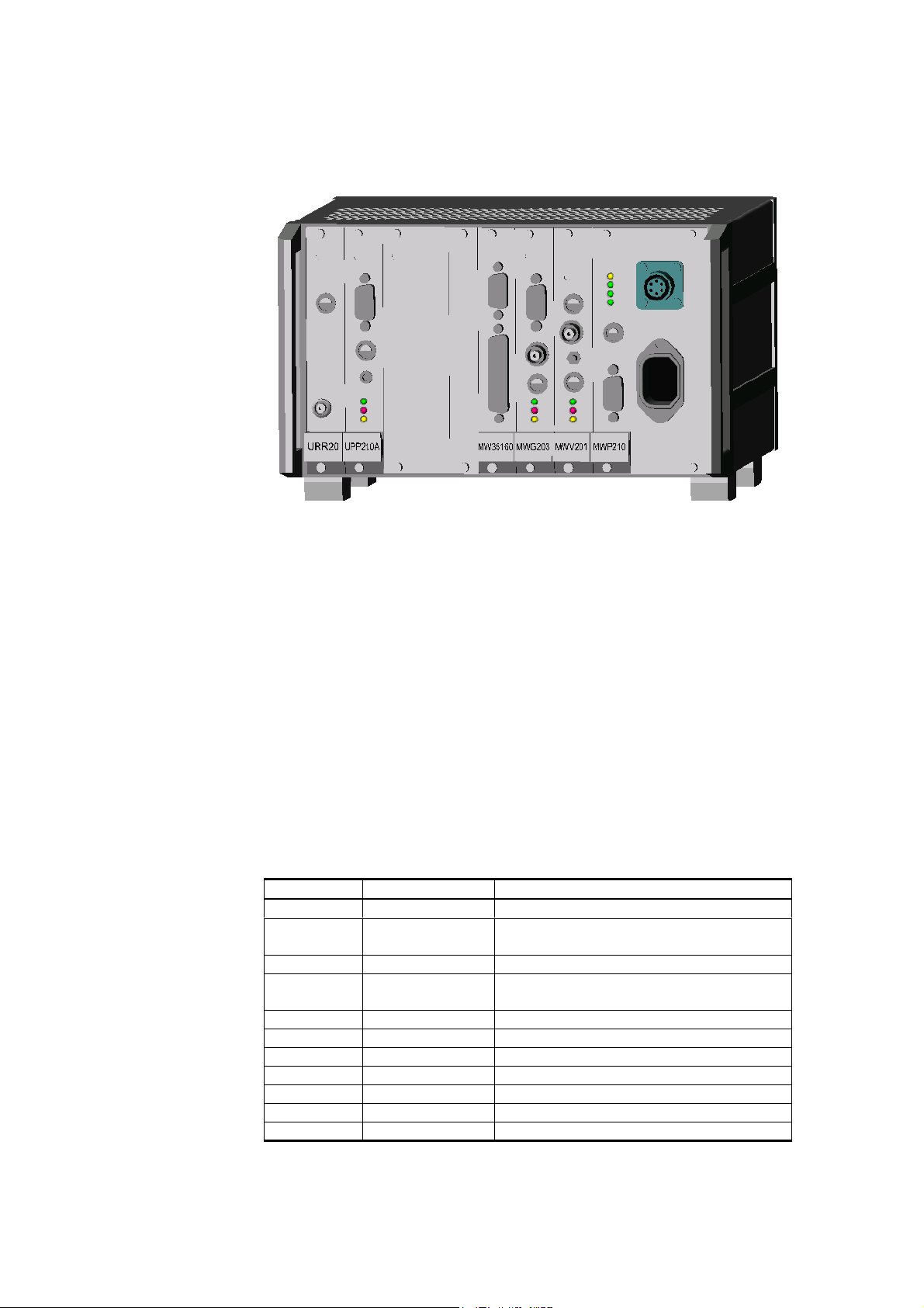
Card Frame MWF210
Table 3 MWF210
Reference Part Number Description
Assembly ref. 1 MW35105 Front Panel Assembly, MWF210
Included in the part
above.
MW35082 Front Panel, MW35082
MW45108 Bushing, MW45108 (M3, L=13.8)
MW45109 Switch and LED Board
3939 Washer, spring B 3 /A4
4765 Screw, slot M 3 x 6 A4m
Assembly ref. 2 MWM210 Motherboard
Assembly ref. 3 25242 Side Panel
Assembly ref. 4 25242 Horizontal rail 30842-141
Assembly ref. 5 25242 Top cover SP45026
Assembly ref. 6 25242 Bottom cover SP45027
Assembly ref. 7 25242 Front corner 30842-231
Assembly ref. 8 25242 Side cover
Assembly ref. 9 25242 Front handle 30842-236
Assembly ref. 10 25242 Gasket set
Assembly ref. 11 25448 Module profile 30837-434
Assembly ref. 12 25448 Thread strip 30819-636
Assembly ref. 13 25448 Insulating strip 60817-118
Assembly ref. 14 25448 Contact plate set 20845-841
Assembly ref. 15 25448 EMC-gasket set 20842-938
Assembly ref. 16 25448 Foot 10603-001
Assembly ref. 17 16713 RFI/EMI Shielding NSOK 3794
Assembly ref. 18 MW45088 Protecting plate MW45088
Assembly ref. 19 MW45107 Bracket MWF210
Assembly ref. 20 MW35084 Strip
Assembly ref. 21 16812 Guide 60817-103
Assembly ref. 22 15223 Sticker Set
Assembly ref. 23 MW45118 Instruction label
Assembly ref. 24 MW35147 Name strip SPS220