VAKI Heathro Fish User manual

Version:March 2014
User Manual
Heathro Fish Pump

Heathro Fish PumpManual
www.vaki.is
Page1
Contents
1. Warranty Terms of Heathro Fish Pump...............................................................................2
2. Neighborhood .......................................................................Error! Bookmark not defined.
3. Explanation of Parts ........................................................................................................4
3.1 The cochlea .................................................................................................................4
3.2 Main engine.................................................................................................................4
3.3 Priming motor..............................................................................................................4
3.4 Priming tank................................................................................................................5
3.5 Priming pump ..............................................................................................................5
3.6 Control cabinet ............................................................................................................5
3.7 Remote Control............................................................................................................6
3.8 Cranes ........................................................................................................................7
3.9 Transitions...................................................................................................................7
3.10 Parts Pack..................................................................................................................7
3.11 Rubber Wheel............................................................................................................8
4. Use of Heathro Fish Pump ................................................................................................8
4.1 Electric model..............................................................................................................8
4.2 Maintenance................................................................................................................9

Heathro Fish PumpManual
www.vaki.is
Page2
1. Warranty Terms of Heathro Fish Pump
VAKI Aquaculture Systems Ltd. Warrantycovers any manufacturing defects occurring within one (1)
year after delivery by VAKI or its reseller, provided that the equipment is installed, used and
maintained in accordancewith instructions for assembly and use.
VAKI undertake to repair such defects caused by construction or materialfaults arising in the
fabrication of the equipment. Such defects will be repaired or replaced. The equipment must be
returned to the manufacturer or authorized representative for the repair.
VAKI offers waranty for any original partsthat are used for repair for a period of one (1) year from
date of delivery.
VAKI is not responsible for:
• Incorrect installation use, or improper care and maintenance.
•Defectscaused by parts, materials, components or equipment not supplied by VAKI and are
obtained , installed or used by the customer without prior written approval from VAKI.
•Defectscaused by modifications to the equipment made by the customer without the written
approval from VAKI.
• Improper or unauthorised repairs made by the customer.
•Normal wear and tear on equipment.
•Improper connection of electric / hydraulic equipment.
•Defectscaused by power surges.
•Damage toelectricalcables.
•Any economic losses caused by the equipment out of service.
If errors or defects occur on the equipment, the customer must report as soon as possible and
without any unreasonable delay to VAKI or representative.
Such report must be submitted no later than two (2) weeks after the warantyperiod, one (1) year
after delivery.
If the customer does not inform VAKI or authorised representative within thetime limits stated
above, thecustomer will not be entitled to any warrantyrepairs or replacementsfor errors or
defects. Repairs to equipment shall be made in accordance with the conditions statedabove.

Heathro Fish PumpManual
www.vaki.is
Page3
2. Environment
The HeathroFish pump is designed to work in all weathers,except for temperaturesbelow 0 ° C
(Celsius).
Use in cold weather can cause damage to hoses and priming system. Heathropump is built on a
chassis with 2 largerubber wheels that cancarry up to 400 kg per wheel, this allows the pump to
easily move over rough and uneven surfaces. The pump is designed to move fish up to 400 g
(salmonids). It is not suitable to pump pebbles , debris or sand.
Electrical needs
An electricalexpert must ensure that appropriate power socket correctly connected to thepump
power cable.

Heathro Fish PumpManual
www.vaki.is
Page4
3. Explanation of Parts
Heathro Fish pump is made of aluminum and fiberglass
and provides very gentle handling of fish during
transport. The pump is 6 "but can be reduced down to 4",
5 "or 3" with purpose made fish friendly cam lock
reducer kits.
The pump is available in three versions, thestandard
electric which is the most popular version , and also
hydraulic and petrol-driven.
Large handles and rubber wheels alow the pump to
easily move around eneven ground. Camlock quick
couplings are used for simple and safe connection of hoses.
3.1 Pump Body
The Heathropump body shell is made using a specially
moulded form developed with over 20 yearsexperience
in the production of fibre glass fish farming equipment.
Inside the pump body there is an aluminum impellor
which leads fish and water through thepump. The
impellor speed can be be fully controlled as required,
either directlyfrom the main pump control box or by
radio remote control.
3.2 Main Motor
The main 4kW motor drives the impellor with twobelts
located under the pump body .
The motor is controlled by a frequency converter (Altivar
31), making it easy to regulate the pumping speed as
required. Note: If the wiring of the the main power
socket is inverted the internal circuit breaker will trip
cutting the power to the main pump preventing the
motor turning in the wrong direction.
3.3 Priming motor
The Priming motor drives the priming pump that creates
the suction inside the main fish pump before the main
pump is started. This motor is 1.5 kW and has no rotation
protection.
Note: If the wiring of the main power socket is inverted
the priming motormay turn in thewrong direction and
must be recitifed .

Heathro Fish PumpManual
www.vaki.is
Page5
3.4 Priming tank
The Priming tank must be filled with water before using
the pump. The water in this tankis used to create
suction in the pumping system.
Only after running the priming pump and when water
startsflowing out the priming sytem outlet can themain
motor/pump can be started. There are two valves to
empty the priming tank and the other to empty the main
pump housing. In freezing temperaturesthe pump may
be damagedif not drained fully after use.
3.5 Priming pump
The priming the pump is connected to the priming motor
by a shaft. On this shaft thereis a coupling that is easy to
replace if necessary (see photo below). The motor is
marked with an arrowshowing which direction it should
turn. It is important to empty the priming pump of water
if there is a danger of frost.
3.6 Control cabinet
The Control unit has seven buttons, switches and lights.
The large red switch at teh bottom of thecabinet is the
main power switch and can only be turned on when the
cabinet door is closed.
There are an on and off button for priming the pump and
also an on and off button for the main pump.
If required it is possible to use the priming pump while
running the main pump. The black button controls the
speed of the main pump and the red light shows if there is
power to the pump or not. The sensitivity of the speed
button can be adjusted as follows:

Heathro Fish PumpManual
www.vaki.is
Page6
1Turn off the power at the main switch and open the door of the control cabinet. The door can not
be opened unless the main switch is turned off.
2Turn on thepower in the cabinet by turning the white shaft of the main switch clockwise. There
will now be electric current in components of the cabinet, so avoid contact with any live
components.
3The Altivar 31 has four buttons and a screen. It should now be rdY thescreen. There is an up and a
down button on the left side and esc and ent touch button on the screen.
4Press (Ent) once and "Set" appears on the screen.
5Press (Ent) againand "ACC"(acceleration)will appear on the screen.
6Press (Ent) againand a value will be displayed on the screen. The ACC value is set to 3.0at the
factory. This value indicates the timein seconds for the main the drive to go from 0 to full speed. A
higher ACC value (longer time period to go from 0 to full speed) will make it easier to have fine
speed adjustments.
7 Use the up / down arrowsto adjust to the desired ACC setting. The Factorysetting @ 3.0,
corresponds to 2.4 Hz per press of the remote control.
Increasing to 6.0s reduces every remote button press to1.2Hz steps.
The Altivar 31 cango from 0 to full speed of 50 Hz
8Press (Ent) to save the new value.
9Press (Esc) to return to the"ACC"
10th Press down arrowto scroll to "dEC" (deccelerate)this time setting the timeto go from full
speed to stop.
11th Press enter and the value of dEC will appear on the screen.
12th Adjust to thedesired value. The value of ACC and dEC need not be equal. Ifdesired, one can
have fine adjustemt on the ACC to allow a slower rate of acceparation speed up while a coarse
adjustment on reducing speed.
13th Press (Ent) to save.
14th Press (Esc) button repeatedly until 'rdY "on screen
15th Test thenew setting and adjust if necessary (Section 4-14)
16th When theadjustment is complete the power is turned off by turning the white shaft of themain
switch counterclockwise.
17th The door of the cabinet is closed.
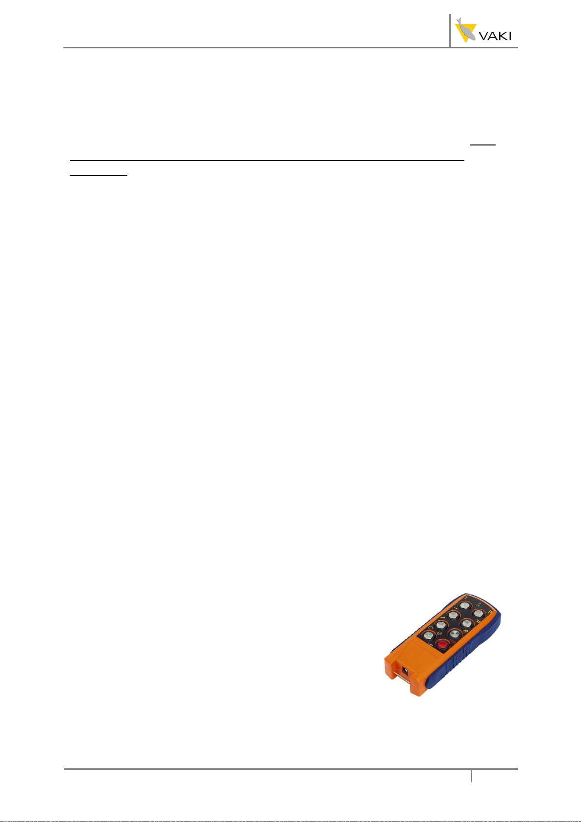
3.7 Remote Control
Wireless remotecontrol is optional and highly recommended. With
this you can start and stop the priming pump and the main pump,
and control the speed of the main pump. (see page10 of the
manual)
Inside the control cabinet there is an antennae for wireless
connection tothe handheld remote unit.
The remote must be rechargedwith thebatterycharger supplied.

Heathro Fish PumpManual
www.vaki.is
Page7
3.8 Valves
On top of the swan neck there is a valve, this is used torelease the vacum formed on the suction side
of the pump. Ifthe suction hose gets stuck open this valve to get the air into the system and loosing
the vacum and releasing the suction hose.
On the main pump outlet thereis a valve to empty and discharge the water on the outlet relieving
the water pressure before removing the outlet hose from the pump.
3.9 Connections and Reducers
There are different sizes of reducers and connections
with Heathrofish pump. The Camlock system is used for
quick and safe connection of hoses. The standardsize is 6
" and 4" but 5“and3“can also be ordered.The
connections aredesigned and manufacturedso that
there are no sharp edges and thefish has a very gentle
treatment during pumping. Ensure that the rubber gasket
is in place so no air is sucked to the suction side.
3.10 Parts Pack
Many customers choose and buy a spare part package
consisting of key partsthat canbe easily replaced.
1 coupler element
2 Cover of the coupler element
3 Impellor for the Jabsco pump priming
4 Adapter ring for the motor
5 Jabsco shaft seal
6 EDPM rubber check valve gasket and the aluminum
plate
7 Drive belt (2 pcs.)
8 Jabsco gasket

Heathro Fish PumpManual
www.vaki.is
Page8
3.11 Rubber Wheel
Heathrofish pump is on large rubber wheels so it's
easy to move it over uneven terrain. Makesure the
air pressure is equal on both wheels and fill grease
cups regularly.
4. Use of Heathro Fish Pump
Heathrofish pump is available in three versions, electric, gasand hydraulic.
4.1 Electric model
Before you start the fish pump.
1 Make sure the main motor and priming motor is turned off.
2 Fill priming tank with water until it is full.
3 Ensure control cabinet is closed and turn on the main switch.
4 Check themain light illuminates on the control cabinet.
5 Make sure the valve on top of the swan neck is closed.
6 Make sure the valves and lid of the priming tankis closed
START THE PRIMING PUMP
1 Check the light on the control cabinet for priming the pump is on.
2 Check the priming pump turns in the right direction. See arrows on the pump. (If priming pump is
turning in the wrong direction, the wiring must be corercted.
3 Run the priming pump until water flows out of the priming tankoutlet
hose.
NOW TURN ON THE MAIN PUMP
AND TURN OFF PRIMING PUMP
1 Check thelights on the control cabinet for the main pump is on.
2 Make sure the belts arenot slipping.
3 Run the engine up to the desired speed.
4 If the pump sucks airand is shuddering then turn on the priming pump
and let the priming pump run while the main pump is also running. The
pump will shake if thereis air in the system, and in this case use the
priming pump.
5 For optimal use, it is very important that the pump does not suck air
and shake so carefully check all connections and hoses on the suction
side to detect and fix any leaks.

Heathro Fish PumpManual
www.vaki.is
Page9
4.2 Maintenance
After the first 24 hours of use:
1 Check the belts have proper tension
Daily Maintenance:
1 Flush the pump and motor with fresh water
2 Check Camlock connections.
3 Check mechanicalparts.
Weeklymaintenance:
1 Lubricate the wheel bearing.
2 Make sure nothing is stuck in the drive belt cover. Check the belts are ok.
3 Check theair in the tires.
4 Check all hoses and connections for leaks
5 Lubricate the pump shaft bearing (under the main pump housing). IMPORTANT: before greasing
remove the screw on the opposite side of the shaft . Remember to replace the screw afterwards.
To switch on the remote control to the pump:
Push the red stop button on top of the remote.
Press Start twice and hold the button the second time, until the
remote control startsblinking green.
Table of contents
Other VAKI Water Pump manuals
Popular Water Pump manuals by other brands

Grundfos
Grundfos Fire NKF Series Installation and operating instructions

Pentair
Pentair SHURFLO BLASTER 4238 Series manual

Edwards
Edwards HV30000 instruction manual

Westfalia
Westfalia 93 91 90 Original instructions

Agilent Technologies
Agilent Technologies MS40-S user manual

Simer
Simer Ace-In-The-Hole A5000 owner's manual

KNF
KNF N963 Operating and installation instructions

Pontec
Pontec PondoSolar 600 Control operating instructions

Pfeiffer Vacuum
Pfeiffer Vacuum OKTA 8000 operating instructions

Werner Weitner
Werner Weitner WW-1 operating instructions

yellow jacket
yellow jacket 93714 Operation and maintenance manual

Edwards
Edwards xds35i instruction manual