VAN DER ENDE Vacon 100 Flow User manual

Vacon 100 Flow page1
Vacon 100 Flow Course
Version 18.10F
19-12-2018
Version 18.10F
Sw:FW0159V021
G:\Data\Iedereen\cursussen\Frequentieregelaars\Vacon\Vacon 100 Flow versie 18.10-eng.doc

Vacon 100 Flow page2
Index
Index........................................................................................................................... 2
Preface ........................................................................................................................ 3
1 Safety ....................................................................................................................... 4
2 Wiring and display...................................................................................................... 6
2.1 Cable diameter and fuses..................................................................................................... 6
2.2 Shielded cables ................................................................................................................... 6
2.3 Control keys........................................................................................................................ 7
2.4 Operation of the display....................................................................................................... 8
2.4.1 Icons ........................................................................................................................... 8
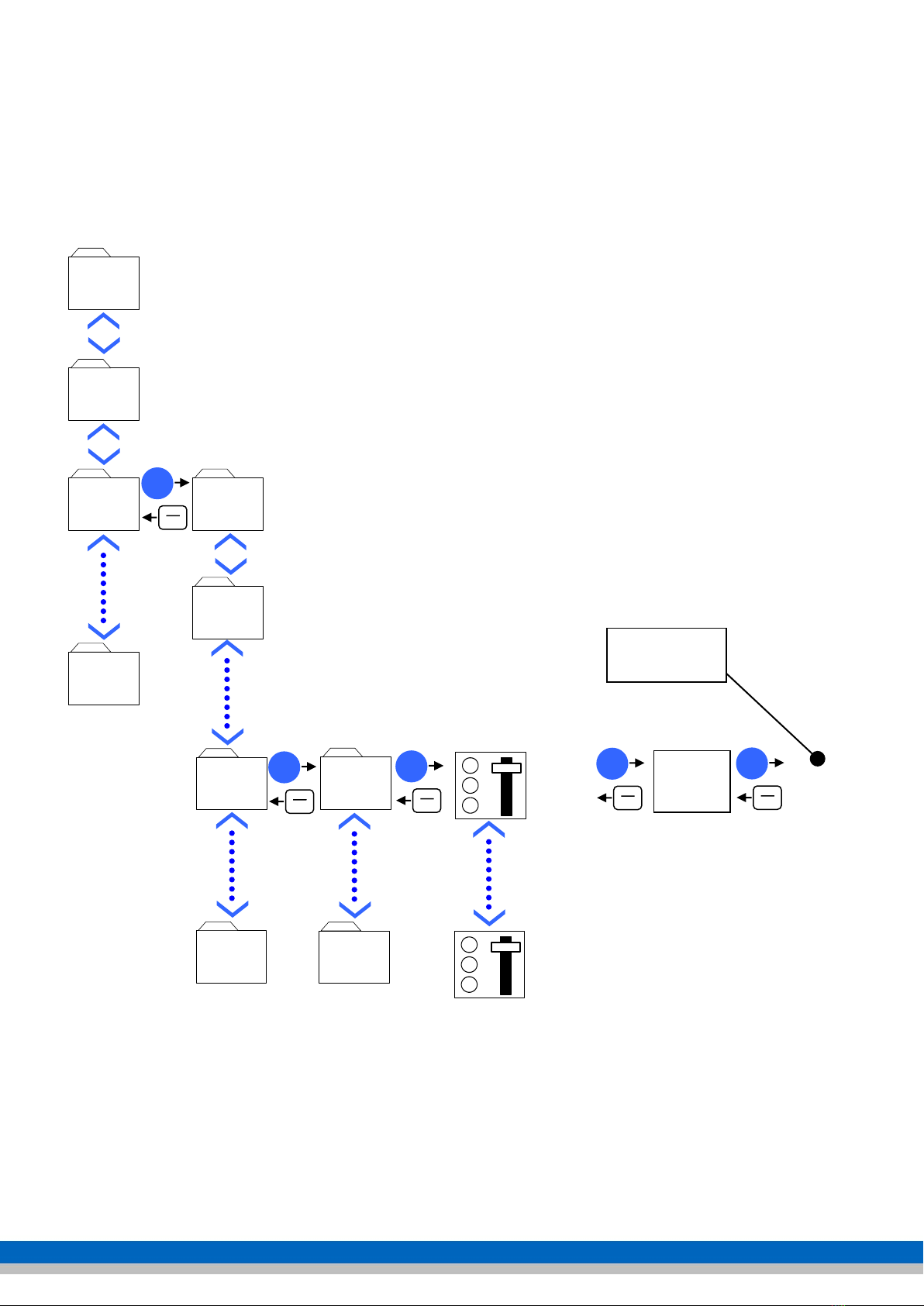
3.1 Scrolling through parameters ............................................................................................... 9
3.2 Viewing and modifying a parameter ..................................................................................... 9
3.3 Monitoring Menu ............................................................................................................... 10
3.3.1 Change multimonitor menu ......................................................................................... 10
3.3.2 Trend Curve ............................................................................................................... 10
3.4 Vacon 100 Wizard. ............................................................................................................ 11
3.5 Startup Wizard. ................................................................................................................. 11
3.6 Quick setup parameter group............................................................................................. 12
3.7 Parameter group setting .................................................................................................... 13
3.8 The distribution of DI (digital inputs).................................................................................. 14
3.8.1 Functions for DI ......................................................................................................... 15
3.9 Favourites folder ............................................................................................................... 17
3.9.1 Saving parameters in the favourites folder ................................................................... 17
3.9.2 Removing parameters from the favourites folder .......................................................... 17
3.10 Cooling fan control .......................................................................................................... 17
3.11 Default page display ........................................................................................................ 18
3.12 Saving and loading parameter setting + factory setting ..................................................... 18
3.13 Parameter lock ................................................................................................................ 18
3.14 Faults and alarms ............................................................................................................ 19
3.14.1 Errors ...................................................................................................................... 19
3.15 Monitoring values ............................................................................................................ 20
4 Vacon Live................................................................................................................21
5 Commissioning the drive............................................................................................22
6 Applications ..............................................................................................................24
6.1 Application defaults ........................................................................................................... 24
6.2 Start Application via Wizard ............................................................................................... 24
6.2.1 Default Application (Wizard)........................................................................................ 25
6.2.1.1 Application example: 0 - 10 V tracking control (using Default Wizard 6.2.1) ............ 26
6.2.1.2 Application example: 4 to 20 mA tracking control (using Default Wizard 6.2.1)........ 27
6.2.1.3 Application example: Up-down control (using Default Wizard 6.2.1)........................ 28
6.2.2 PID-Control Application (Wizard) ................................................................................. 29
6.2.2.1 Application example: PID control (using PID control Wizard 6.2.2).......................... 30
6.2.2.2 Terminals ............................................................................................................ 32
7 Pressurised Water Systems ........................................................................................33
7.1 Pressurised water system wiring plan (PID) ........................................................................ 33
7.2 Setting up pressurised water systems ................................................................................. 34
8 Multi-Pump ...............................................................................................................35
8.1 Multi-Pump Single Drive/Multi-Drive ................................................................................... 35
8.2 Multi-pump Multi-drive application (Wizard) ........................................................................ 36
8.2.1 Application example: Multi-pump Multi-drive (Via Multi-pump Wizard 8.2)...................... 37
Notes..........................................................................................................................39

Vacon 100 Flow page3
Preface
This course book is issued to those who have followed the Vacon 100 Flow course at Van
der Ende pompen BV. It is also issued with each Vacon 100 Flow regulator.
The course book is also intended as a quick and handy instruction manual for commissioning
the Vacon 100 Flow. This textbook also shows a few sample applications.
We therefore emphatically recommend that the original instruction manuals provided with
the regulator are always read very carefully.
No rights can be derived from the information provided in this course book.
Errors and/or typographical errors that could result in incorrect settings and/or damage to
the regulator or connected equipment may never give rise to warranty or damage claims,
and are hereby expressly rejected.
The parameters listed in this booklet are merely examples from which no rights can be
derived.
In this new version, a number of parameters have been changed or added compared to the
previous version.
Copyright Van der Ende pompen BV.
No part of this publication may be reproduced and published without written permission of
Van der Ende pompen BV.

Vacon 100 Flow page4
1 Safety
1
The components of the power unit of the frequency
converter are live when the Vacon 100
is connected to the mains. Contact with this live voltage is
extremely dangerous, and can result in serious injuries or
death.
The control unit is potential-free.
2
The Vacon 100 has a leakage current of 3.5 mA AC according
to EN61800-5-1.
3
If the frequency converter is part of a machine, the machine
manufacturer is responsible for installing a main switch for
the machine (EN 60204-1).
4
Only spare parts supplied by Vacon may be used.
5
The motor cables must be disconnected from the frequency
converter before insulation and other measurements are
carried out on the motor or motor cables.
6
Do not touch the IC-circuits on the boards.
Static voltage can damage the components.
7
Check that the EMC level of the frequency converter
corresponds to the required value as determined by the
environment.
8
The motor starts automatically if you set the parameter
setting
(ID 731) ‘reaction after an error message’ to automatic. Read
more about this in the application manual.
9
The Vacon 100 frequency converter must be used for
permanent installations.
10
Be aware that the frequency converter can start
automatically when it is connected to the power supply. To
prevent this, unplug the motor from the frequency converter
if sudden starting might be hazardous.
ONLY QUALIFIED TECHNICIANS MAY CARRY OUT WORK
ON THE ELECTRICAL INSTALLATION
WARNING

Vacon 100 Flow page5
1
The U, V, and W motor terminals and the DC rail / brake
resistor -/+ terminals are live when the Vacon 100 is
connected to the mains, even if the motor is not running.
2
The I/O connectors for the controllers are electrically isolated
from the mains. However, even when the Vacon 100 is
disconnected from the mains, the relay outputs and other I/O
terminals may have a dangerous external voltage.
3
Before the frequency converter is connected to the mains,
make sure that the Vacon 100 covers and cable connections
are covered.
4
Do not carry out any measurements when the frequency
converter is connected to the mains.
5
After disconnecting the frequency converter from the mains,
wait until the fan stops and the control panel turns off (if no
panel is attached, see the indicators on the cover). Wait 5
minutes before performing any work on the Vacon 100
terminals.
Do not even open the cover before this time has passed.
6
Do not perform any insulation resistance tests on the Vacon
100. There is a specific procedure for carrying out such tests.
Failure to follow this procedure may cause damage to the
device.
Safety instructions
Earthing and earth error protection
The Vacon 100 frequency converter must always be earthed on the
earth terminal

Vacon 100 Flow page6
2 Wiring and display
2.1 Cable diameter and fuses
Frame
Type
IL
[A]
Fuse
(gG/g
L) [A]
Mains and motor
cable
Cu [mm2]
Terminal size
Mains
connection
[mm2]
Earth
connection
[mm2]
MR4
0003 4 - 0004 4
3.4 to 4.8
6
3 x 1.5 + 1.5
1 to 6 solid
1 to 4 flexible
1 to 6
0005 4 -0008 4
5.6 to 8.0
10
3 x 1.5 + 1.5
1 to 6 solid
1 to 4 flexible
1 to 6
0009 4 -0012 4
9.6 to 12.0
16
3 x 1.5 + 1.5
1 to 6 solid
1 to 4 flexible
1 to 6
MR5
0016 4
16.0
20
3 x 6 + 6
1 to 10 Cu
1 to 10
0023 4
23.0
25
3 x 6 + 6
1 to 10 Cu
1 to 10
0031 4
31.0
32
3 x 10 + 10
1 to 10 Cu
1 to 10
MR6
0038 4
38.0
40
3 x 10 + 10
2.5 to 50 Cu/Al
2.5 to 35
0046 4
46.0
50
3 x 16 + 16 (Cu)
3 x 25 + 16 (Al)
2.5 to 50 Cu/Al
2.5 to 35
0061 4
61.0
63
3 x 25 + 16 (Cu)
3 x 35 + 10 (Al)
2.5 to 50 Cu/Al
2.5 to 35
MR7
0072 4
72.0
80
3 x 35 + 16 (Cu)
3 x 50 + 16 (Al)
6 to 70 Cu/Al
6 to 70
0087 4
87.0
100
3 x 35 + 16 (Cu)
3 x 70 + 21 (Al)
6 to 70 Cu/Al
6 to 70
0105 4
105.0
125
3 x 50 + 25 (Cu)
3 x 70 + 21 (Al)
6 to 70 Cu/Al
6 to 70
MR8
0140 4
140.0
160
3 x 70 + 35 (Cu)
3 x 95 + 29 (Al)
Bolt size M8
Bolt size M8
0170 4
170.0
200
3 x 95 + 50 (Cu)
3 x 150 + 41 (Al)
Bolt size M8
Bolt size M8
0205 4
205.0
250
3 x 120 + 70 (Cu)
3 x 185 + 57 (Al)
Bolt size M8
Bolt size M8
MR9
0261 4
261.0
315
3 x 185 + 95 (Cu)
2 x 3 x 120 + 41 (Al)
Bolt size M8
Bolt size M8
0310 4
310.0
350
2 x 3 x 95 +50 (Cu)
2 x 3 x 120 + 41 (Al)
Bolt size M8
Bolt size M8
2.2 Shielded cables
The cables of the control signals and of the motor must be shielded in order to meet radio
interference rules, in accordance with IEC 60364-5-52 and EMC specifications.
The shielding of the motor and control cables must be connected to the earth terminal in
the frequency converter and in the motor and sensors, PLC etc.
If unshielded cables are used, signal interference can occur in the control inputs. Such
interference will not normally damage the frequency converter, but will interfere with
regulation.
Max. length of motor
cable
MR4
MR5 and MR6
MR7, MR8 and MR9
100 m
150 m
200 m
Be careful! Reinforcement designed as mechanical protection (e.g. earth cable) is not
suitable for an EMC-correct installation.
Our preference is to use twisted cable for signal cables.

Vacon 100 Flow page7
2.3 Control keys
Back/Reset
This key returns you to the menu. You can also use this key to end an entry without it being
stored.
If a problem has been resolved, the frequency converter can be reset by holding this key for
a few seconds.
Funct
The funct key can be used anywhere in the programme to switch from Local (keypad) to
Remote (I/O or fieldbus) operation. The operation page can also be selected.
OK
This key allows you to enter a folder or parameter. It also confirms a change to a parameter
(stored in EPROM).
Menu key up
Use this key to scroll up through main menus and sub-menus, or change the value in a
parameter.
Menu key down
Use this key to scroll down through main menus and sub-menus, or change the value in a
parameter.
Menu key left
This key can be used when changing each digit of a parameter.
Menu key right
This key can be used when changing each digit of a parameter.
If the parameter is selected, you can change the parameter immediately by holding down
this key.
Start
This key starts the motor when in local control mode (see Loc/Rem).
Stop
This key stops the motor when in local control mode (see Loc/Rem). In remote control
mode, this key also stops the motor when "keypad stop key" is enabled (parameter M3.2.2).
Start
Stop

Vacon 100 Flow page8
2.4 Operation of the display
The information appearing on the display is divided into menus and submenus.
Scroll through the menus with the up and down arrow keys.
To enter a group, press the OK key.
To return to the previous level, press the Back/
Reset
key.
The location field indicates the menu in which frequency converter can be found.
2.4.1 Icons
File folder
Folder with monitoring parameters
Folder with error history
Favourites folder
Folder with parameters
Parameter
Multiselect parameter
Monitor parameter
Status monitor parameter
Multi-monitoring (9/6/4 parameters in 1 image)
Help
Add to favourites
View details of selected error
Reset active error + retrieve or store parameters
Remove from favourites
Load/save parameter settings
Status: Ready,
Not ready, error
Operating location: PC, I/O,
fieldbus or control panel
Location field: Parameter
ID number and current menu
location
To activate this group (black), press
OK
Number of items in the
group or display
controller
Status: ALARM
Status: STOP or RUN
Direction of
rotation

Vacon 100 Flow page9
3 Parameters
3.1 Scrolling through parameters
main menu
M1
M2
M3
M3.1
OK
BACK
RESET
M7
M3.2
OK
BACK
RESET
M3.5
M3.5.1
M3.5.4
OK
BACK
RESET
Parameter
P3.5.1.1
M3.16
OK
BACK
RESET
Edit
Parameter
P3.5.1.45
OK
BACK
RESET
Change
parameter

Vacon 100 Flow page10
3.2 Viewing and modifying a parameter
For example, we want to view and change the maximum frequency (P 3.3.1.2).
Go to the Main Menu, and scroll up or down with the arrow keys to the Parameters folder,
then press OK. Scroll through this menu to References, then press OK.
Scroll to Max. frequency, and press OK.
You have three options; Edit/Help/Add to favourites.
Scroll to Edit, then press OK (the value now starts to flash).
The target frequency can now be entered with the arrow keys.
The place where the change
is being made can also be selected with the left and right arrow keys. This figure is
underlined.
After changing the value, you can save it by pressing OK.
3.3 Monitoring Menu
In the monitoring menu, monitor values can be displayed simultaneously via multimonitor 9,
6 or 4. A graph with 2 monitor values can be viewed via the trend curve.
3.3.1 Change multimonitor menu
If you hover over one of the Multimonitor fields and then press OK, you can select the
required monitor parameter by scrolling up or down, and confirm with the OK key.
The number of display fields can be changed with parameter (P3.11.4); the options are 3x3,
3x2 and 2x2
3.3.2 Trend Curve
Selecting a monitor value below the graph shows a graph of this value. In
the trend menus, it is possible to adjust the interval time and the minimum
and maximum of the value to be displayed, or to switch to auto-scaling.
OK
OK

Vacon 100 Flow page11
3.4 Vacon 100 Wizard.
The Startup Wizard allows you to quickly change the basic settings to values that best suit
your application.
The following keys are used in the wizard:
Arrows left and right; these change digits and decimals.
Arrows up and down; scroll through the various options, and change
values.
This confirms the selection.
Pressing this key returns you to the previous question in the wizard. If this key is
pressed during the first question, the wizard closes.
3.5 Startup Wizard.
When the frequency converter is started for the first time, it automatically starts the Startup
Wizard, which can also be started with parameter (P1.1.1)
Setting
Value
1
Language selection
2
Daylight saving time(only with a battery power
supply)
Russia
US
EU
OFF
3
Time setting
hh:mm:ss
4
Year setting
- - - -
5
Date setting
dd:mm
6
Use Startup Wizard?
Yes
No (exit wizard)
7
Application
Standard
HVAC
PID control
Multi-pump (single drive)
Multi-pump (multi-drive)
8
Motor type
PM motor (permanent magnet)
Induction motor
Reluctance motor
9
Rated motor voltage(see motor nameplate)
Varies
10
Rated motor frequency(see motor nameplate)
8 to 320 Hz.
11
Rated motor speed(see motor nameplate)
24 to 19,200 rpm
12
Rated motor current(see motor nameplate)
Varies
13
Motor Cos Phi (see motor nameplate)
0.30 to 1.00
14
Minimum frequency
0 to max. frequency Hz.
15
Maximum frequency
min frequency to 320 Hz.
16
Acceleration time 1
0.1 to 3,000 sec
17
deceleration time 1
0.1 to 3,000 sec
18
Application Wizard
Yes*
No (exit wizard)
*) If yes is selected, the key parameters are gone through for each application.
BACK
RESET
OK

Vacon 100 Flow page12
3.6 Quick setup parameter group
In addition to the Startup Wizard, the Vacon 100 has a quick setup menu for the most basic
parameters.
By changing a setting in the quick setup parameter group, this setting will also be changed
in the corresponding parameter group.
code
Parameter
Min
Max
ID
M1.1
Wizards
Starting various wizards
P1.2
Application
212
Standard
HVAC
PID control
Multi-pump (single drive)
Multi-pump (multi-drive)
P1.3
Minimum frequency
0
50
Hz
101
P1.4
Maximum frequency
20
320
Hz
102
P1.5
Acceleration time 1
0.1
3,000
s
103
P1.6
Deceleration time 1
0.1
3,000
s
104
P1.7
Current limit
3
variable
A
107
P1.8
Motor type
PM
Induction
PM motor (permanent magnet)
Induction motor
P1.9
Rated motor voltage
180
690
V
110
P1.10
Rated motor frequency
0
320
Hz
111
P1.11
Rated motor speed
0
62,500
RPM
112
P1.12
Rated motor current
0
variable
A
113
P1.13
Motor Cos phi
0
1
120
P1.14
Energy optimisation
enable
disable
666
P1.15
Identification
631
No action
At standstill
With the motor running
P1.16
Start function
505
Running start
Ramping
P1.17
Stop function
506
Ramping
Freewheel
P1.18
Automatic reset
enable
disable
731
P1.19
External error
701
No action
Alarm
Error
Error, freewheel
P1.20
Error AI too low
700
No action
Alarm
Alarm fixed frequency
Alarm last frequency
Error
Error, freewheel
P1.21
Remote operating
location
Fieldbus
I/O
terminal
172
P1.22
Reference selection I/O
117
For options, see manual
P1.23
Control panel selection
121
For options, see manual
P1.24
Fieldbus reference
selection
122
For options, see manual
P1.25
AI 1 signal range
0 to 10 V
0 to 20 mA
2 to 10 V
4 to 20 mA
379
P1.26
AI 2 signal range
0 to 10 V
0 to 20 mA
2 to 10 V
4 to 20 mA
390
P1.27
RO1 function
11001
For options, see manual
P1.28
RO2 function
11004
For options, see manual
P1.29
RO3 function
11007
For options, see manual
P1.30
AO1 function
10050
For options, see manual
The following parameters may differ, depending on the choice of the application.
P1.31. ... for Standard and HVAC
P1.32. ... for PID control
P1.33. ... for multitopump (single drive)
P1.34. ... for multitopump (multitodrive)

Vacon 100 Flow page13
3.7 Parameter group setting
The following menus are available in this parameter group:
Code Group name Code Group name
P3. Parameters
3.1. Motor settings
3.1.1. Motor nameplate
3.1.2. Motor control
3.1.3. Limits
3.1.4. Open loop
3.1.4.12. I/f start
3.2. Start/Stop settings
3.3. References
3.3.1. Frequency reference
3.3.3. Fixed frequencies
3.3.4. Motor potentiometer
3.3.6. Flushing
3.4. Ramping and Brakes
3.4.1. Ramp 1
3.4.2. Ramp 2
3.4.3. Start magnetisation
3.4.4. DC brake
3.4.5 Flux Braking
3.5. I/O Configuration
3.5.1. Digital inputs
3.5.2. Analogue inputs
3.5.2.1. Analogue input 1
3.5.2.2. Analogue input 2
3.5.2.3. Analogue input 3
3.5.2.4. Analogue input 4
3.5.2.5. Analogue input 5
3.5.2.6. Analogue input 6
3.5.3. Digital outputs
3.5.3.2. Slot B base
3.5.4. Analogue outputs
3.5.4.1. Slot A base
3.6. Fieldbus data map
3.7. Prohibited frequencies
3.8. Monitoring limit values
3.9. Protection
3.9.1. General
3.9.2. Motor thermal protection
3.9.3. Motor blocked
3.9.4. Underload
3.9.5. Quick stop
3.9.8. AI low level protection
3.10. Automatic reset
3.11. Application settings
3.12. Timer functions
3.12.1. Interval 1
3.12.2 Interval 2
3.12.3. Interval 3
3.12.4. Interval 4
3.12.5. Interval 5
3.12.6. Timer 1
3.12.7. Timer 2
3.12.8. Timer 3
3.13. PID regulator
3.13.1. Basic settings
3.13.2. Reference values
3.13.3. Feedbacks
3.13.4. Forward control
3.13.5. Sleep function
3.13.6. Feedback monitoring
3.13.7. Pressure loss
compensation
3.13.8. Slow fill
3.13.9. Inlet pressure monitoring
3.13.10. Sleep no request
detected
3.13.12. Multi setpoint
3.14. Ext PID regulator
3.14.1 Basic settings
3.14.2. Reference values
3.14.3. Feedbacks
3.14.4. Feedback monitoring
3.15. Multi-pump
3.15.17. Locking signals
3.15.18. Overpressure monitoring
3.15.19. Pump running time
3.15.22. Advanced settings
3.16. Maintenance counters
3.17. Fire mode
3.18. Motor preheater
3.19. Frequency convertor
customisation
Divided into 10 blocks
3.21. Pump control
3.21.1. Auto cleaning
3.21.2. Jockey pump
3.21.3. Preparation pump
3.21.4. Anti-blocking
3.21.5. Frost protection

Vacon 100 Flow page14
3.8 The distribution of DI (digital inputs)
In the Vacon 100, settings can be per function as to how this has to be activated. This
allows multiple functions to be activated with the same DI. It is also possible to control a
function with a timer (M3.12), fieldbus or programming block. (M3.19)
The DI can be located in different slots. The standard DIs from 1 to 6 are located on slot A.
Depending on the choice of DI expansion, the other DIs may be located on slot C, D or E.
All functions are displayed in parameter group M3.5.1. To associate a function to a DI, first
specify in which slot this input is located. Then select the correct DI.
Please note !! When you change a DI, the DI may also be used by another function!
If a function is not in use, it can be set to slot 0. For the regulator, this function does remain
active. That means that if a function requests a NO contact, set it to slot 0.1, and if a
function requests a NC contact, set it to slot 0.2. Example: If the parameter P3.5.1.11 (close
external error) is not used, it should be set to 0.1. Merely changing from slot A (A.3) to slot
0 (0.3) is not sufficient, because the regulator will see a closed contact and generate an
error.
Slot 0.1: makes the function false. (Open contact)
Slot 0.2 and higher: makes the function true. (Closed contact)
Slot A
Slot B
Slot C
Slot D
Slot E
Slot A
Slot B
DI 1,2,3
DI 4,5,6

Vacon 100 Flow page15
3.8.1 Functions for DI
Default
Code
Parameter
slot
position
Description
P3.5.1.1
Control signal 1 A
A
1
If I/O A is the operating location (forward)
P3.5.1.2
Control signal 2 A
A
2
If I/O A is the operating location (reverse)
P3.5.1.3
Control signal 3 A
0
1
If I/O A is the operating location
P3.5.1.4
Control signal 1 B
0
1
If I/O B is the operating location
P3.5.1.5
Control signal 2 B
0
1
If I/O B is the operating location
P3.5.1.6
Control signal 3 B
0
1
If I/O B is the operating location
P3.5.1.7
Force to I/O B control signal
0
1
Select control signal B
P3.5.1.8
Force to I/O B reference
0
1
Use reference value control signal B (M3.3.1.6)
P3.5.1.9
Force to fieldbus control
0
1
Force operation to fieldbus
P3.5.1.10
Force to display operation
0
1
Force operation to control panel
P3.5.1.11
Close external error
A
3
Open: OK
Closed: External error
P3.5.1.12
Open external error
0
2
Open: External error
Closed: Ok
P3.5.1.13
Close error reset
A
6
Closed: Reset all active errors
P3.5.1.14
Open error reset
0
1
Open: Reset all active errors
P3.5.1.15
Release
0
2
Closed: regulator is ready
P3.5.1.16
Start block 1
0
2
Open: Regulator ready, starting blocked
Closed: Regulator can be started
P3.5.1.17
Start block 2
0
2
Open: Regulator ready, starting blocked
Closed: Regulator can be started
P3.5.1.18
Preheating ON
0
1
Open: No action
Closed: Preheat activated if (P3.18.1 is set to 2)
P3.5.1.19
Ramp 2 selection
0
1
Switching between ramp 1 and 2
P3.5.1.20
Acc/dec prohibited
0
1
Open: Acceleration and deceleration permitted
Closed: Acceleration and deceleration not permitted
P3.5.1.21
Fixed frequency selection 0
A
4
Binary selection for fixed frequency
P3.5.1.22
Fixed frequency selection 1
A
5
Binary selection for fixed frequency
P3.5.1.23
Fixed frequency selection 2
0
1
Binary selection for fixed frequency
P3.5.1.24
Increase motor pot
0
1
Motor pot reference goes up
P3.5.1.25
Decrease motor pot
0
1
Motor pot reference goes down
P3.5.1.26
Quick stop activation
0
2
Open: Activated according to (P3.9.5)
P3.5.1.27
Timer 1
0
1
Start Timer 1 programmed with parameters (P3.12.6)
P3.5.1.28
Timer 2
0
1
Start Timer 2 programmed with parameters (P3.12.7)
P3.5.1.29
Timer 3
0
1
Start Timer 3 programmed with parameters (P3.12.8)
P3.5.1.30
PID 1 reference increase
0
1
Open: No amplification
Closed: Amplification
P3.5.1.31
PID 1 SP selection
0
1
Open: Reference value 1
Closed: Reference value 2
P3.5.1.32
External PID - start signal
0
2
Open: External PID stopped
Closed: External PID controls (P3.14)
P3.5.1.33
External PID SP selection
0
1
Open: Reference value 1
Closed: Reference value 2
P3.5.1.34
Reset maintenance counter 1
0
1
Closed: Reset maintenance counter
P3.5.1.36
Activate flushing reference
0
1
Closed: Flushing function active (P3.3.6.2)
Please note! Regulator starts when activating this function
P3.5.1.38
Open fire mode activation
0
2
Open: Fire mode active (M3.17)
Closed: No action

Vacon 100 Flow page16
Default
Code
Parameter
slot
position
Description
P3.5.1.39
Close fire mode activation
0
1
Open: No action
Closed: Fire mode active (M3.17)
P3.5.1.40
Fire mode reverse
0
1
Open: Forward
Closed: Reverse This function is only active in fire mode
P3.5.1.41
Auto cleaning active
0
1
Closed: Auto cleaning active (on opening, the function stops)
Please note! Regulator starts when activating this function
P3.5.1.42
Pump 1 block
0
1
Open: Inactive
Closed: Active
P3.5.1.43
Pump 2 block
0
1
Open: Inactive
Closed: Active
P3.5.1.44
Pump 3 block
0
1
Open: Inactive
Closed: Active
P3.5.1.45
Pump 4 block
0
1
Open: Inactive
Closed: Active
P3.5.1.46
Pump 5 block
0
1
Open: Inactive
Closed: Active
P3.5.1.47
Pump 6 block
0
1
Open: Inactive
Closed: Active
P3.5.1.48
Pump 7 block
0
1
Open: Inactive
Closed: Active
P3.5.1.49
Pump 8 block
0
1
Open: Inactive
Closed: Active
P3.5.1.52
Energy counter reset
0
1
Closed: Energy trip counter reset
P3.5.1.53
Parameter set 1/2 selection
0
1
Open: Parameter setting 1 is selected
Closed: Parameter setting 2 is selected
P3.5.1.54
Multi setpoint select 0
0
1
Binary selection for multi setpoint
P3.5.1.55
Multi setpoint select 1
0
1
Binary selection for multi setpoint
P3.5.1.56
Multi setpoint select 2
0
1
Binary selection for multi setpoint
P3.5.1.57
Multi setpoint select 3
0
1
Binary selection for multi setpoint
P3.5.1.58
Flow switch
0
2
Select digital input flow switch
P3.5.1.59
AHF over temperature
0
1
Activate AHF over temperature
The default values listed above are applicable when using the default application. These
values may change if other applications are used

Vacon 100 Flow page17
3.9 Favourites folder
The Vacon 100 frequency converter allows compilation of a folder containing frequently-
used parameters. It means you can access all the parameters from a single folder, and
modify them if necessary. Please note! The favourites folder is deleted when changing the
firmware, although it can be saved in the control panel.
3.9.1 Saving parameters in the favourites folder
3.9.2 Removing parameters from the favourites folder
3.10 Cooling fan control
Parameter P5.6.1.1 (Fan optimisation) turns the unit's cooling fan on or off. (From MR6
speed control)
If this parameter is switched on, the cooling fan will be switched to the unit temperature.
When switching the power supply on, the cooling fan will always run and then turn off after
around 5 minutes, if:
- the regulator is in ready or sleep state.
- the unit temperature is not too high.
If the regulator is in run mode, the fan will run continuously regardless of the temperature
of the unit.
OK
OK
OK
OK
OK
OK
OK

Vacon 100 Flow page18
3.11 Default page display
Parameter P5.7.2 allows the default page to be determined (e.g. Multimonitor). The timeout
period is entered in parameter P5.7.1.
If the keys of the regulator are not used before the pre-set timeout period, the display will
return to the default page.
3.12 Saving and loading parameter setting + factory setting
Parameter backup allows saved parameter settings to be loaded from the control panel. In
addition, factory settings can also be loaded, and 2 user-defined parameter settings saved
or loaded.
3.13 Parameter lock
To prevent unauthorised changes, it is possible to hide the parameter folders with an access
code.
Go to parameter M8.2, and set an access code to protect parameters. Go to parameter M8.1
and change to monitor or favourites.
Monitor: only the monitoring and main menus are visible
Favourites: Only main menus visible, and only parameters in favourites are available.
The parameter lock is deactivated by setting parameter M8.1 to normal and confirming with
the access code.
Please note!
Make arrangements within your organisation on the use of this code, so that your colleagues
can also modify this control.
OK
OK
OK
OK
OK

Vacon 100 Flow page19
3.14 Faults and alarms
Menu M4 (diagnosis) contains active errors and the error history.
3.14.1 Errors
Error
code
Error
Error
code
Error
1
Overcurrent
2
Overvoltage
3
Earthing error
5
Charging switch
7
Saturation trip
8
System error
9
Undervoltage
10
Input phase
11
Monitoring output phase
12
Braking chopper monitor
13
Heatsink temperature too low
14
Heatsink temperature too high
15
Motor blocked
16
Motor temperature too high
17
Motor under load
19
Overload power
25
Operation error motor
26
Cannot start
29
ATEX - thermistor
30
Safety configuration
32
Fan cooling
33
Fire mode enabled
37
Component changed
38
Component added
39
Component removed
40
Component unknown
41
IGBT temperature
44
Component changed
45
Component added
46
Real-time clock
47
Software update
50
Error AI too low
51
External error
52
Keypad communication error
53
Fieldbus error
54
Option board slot error
57
Identification
63
Fault/alarm quick stop
65
PC communication error
66
Thermistor error
68
Fault/alarm maintenance counter
69
Fieldbus indication error
76
Start blocked
77
> 5 connections
100
Timeout slow fill
101
PID 1 outside pre-set values
105
PID 2 outside pre-set values
109
Inlet pressure monitoring
111
Temperature error 1
112
Temperature error 2
113
Pump running time
300
Not supported
Errors are explained in the application manual.

Vacon 100 Flow page20
3.15 Monitoring values
Monitor value, I/O
Value
ID
V2.4.1
Slot A DIN 1,2,3
15
V2.4.2
Slot A DIN 4,5,6
16
V2.4.3
Slot B RO 1,2,3
17
V2.4.4
Analogue input 1
%
59
V2.4.5
Analogue input 2
%
60
V2.4.6
Analogue input 3
%
61
V2.4.7
Analogue input 4
%
62
V2.4.8
Analogue input 5
%
75
V2.4.9
Analogue input 6
%
76
V2.4.10
Slot A AO1
%
81
Monitor value, Temperature inputs
Value
ID
V2.5.1
Temperature input 1
° C/F
50
V2.5.2
Temperature input 1
° C/F
51
V2.5.3
Temperature input 1
° C/F
52
V2.5.4
Temperature input 1
° C/F
69
V2.5.5
Temperature input 1
° C/F
70
V2.5.6
Temperature input 1
° C/F
71
Monitor value, Timer functions
Value
ID
V2.7.1
TC 1, TC 2, TC 3
1441
V2.7.2
Interval 1
1442
V2.7.3
Interval 2
1443
V2.7.4
Interval 3
1444
V2.7.5
Interval 4
1445
V2.7.6
Interval 5
1446
V2.7.7
Timer 1
1447
V2.7.8
Timer 2
1448
V2.7.9
Timer 3
1449
V2.7.10
Real-time clock
1450
Monitor value PID regulator
Value
ID
V2.8.1
PID1 reference value
var.
20
V2.8.2
PID1 feedback
var.
21
V2.8.3
PID1 feedback (1)
var
15541
V2.8.4
PID1 feedback (2)
var
15542
V2.8.5
PID1 error value (difference)
var.
22
V2.8.6
PID1 output value
%
23
V2.8.7
PID1 status
24
Monitor value, External PID regulator
Value
ID
V2.9.1
External PID reference value
var.
83
V2.9.2
External PID actual value
var.
84
V2.9.3
External PID error value
(difference)
var.
85
V2.9.4
External PID output value
%
86
V2.9.5
External PID status
87
Multi-pump monitor
Value
ID
V2.10.1
No. of motors in operation (active)
30
V2.10.2
Autochange
1113
V2.10.3
Next autochange
1503
V2.10.4.
Operating mode
1505
V2.10.5
Multi-pump, status
15507
V2.10.6
Communication status
15506
V2.10.7
Pump (1) running time
h
15510
V2.10.8
Pump (2) running time
h
15511
V2.10.9
Pump (3) running time
h
15512
V2.10.10
Pump (4) running time
h
15513
V2.10.11
Pump (5) running time
h
15514
V2.10.12
Pump (6) running time
h
15515
V2.10.13
Pump (7) running time
h
15516
V2.10.14
Pump (8) running time
h
15517
Monitor value, Maintenance counters
Value
ID
V2.11.1
Maintenance counter 1
h/kRev
1101
Monitor value, Fieldbus
Value
ID
V2.12.1
to
V2.12.20
Various Fieldbus values
864
to
883
Monitor Drive Customizer
Value
ID
V2.13.1
to
V2.13.11
Various Drive Customizer values
15020
to
15200
Monitor value, Base
Value
ID
V2.3.1
Output frequency
Hz
1
V2.3.2
Reference frequency
Hz
25
V2.3.3
Motor speed
RPM
2
V2.3.4
Motor current
A
3
V2.3.5
Motor torque
%
4
V2.3.7
Motor shaft power
%
5
V2.3.8
Motor shaft power
kW/hp
73
V2.3.9
Motor voltage
V
6
V2.3.10
DC link voltage
V
7
V2.3.11
Unit temperature
oC
8
V2.3.12
Motor temperature (calculated)
%
9
V2.3.13
Motor preheater
1228
V2.3.15
kWh trip counter low
kWh
1054
V2.3.16
kWh trip meter high
kWh
1067
Monitor value, Extras & Advanced
Value
ID
V2.6.1
Frequency convertor status word
43
V2.6.2
Ready
78
V2.6.3
Application status word 1
89
V2.6.4
Application status word 2
90
V2.6.5
DIN status word 1
56
V2.6.6
DIN status word 2
57
V2.6.7
Motor current 1 decimal
45
V2.6.8
Frequency reference source
1495
V2.6.9
Last active error code
37
V2.6.10
Last active error ID
95
V2.6.11
Last active alarm code
74
V2.6.12
Last active alarm ID
94
V2.6.13
Status motor regulator
77
V2.6.14
Motor shaft power 1 decimal
kW
98
Table of contents
Other VAN DER ENDE Water Pump manuals
Popular Water Pump manuals by other brands

Pumpex
Pumpex P 401 Starting and operating instructions

Pond Boss
Pond Boss PF40SOL manual

JABSCO
JABSCO Hy-Line Installation, Operating, Maintenance and Spares Manual

PERMCO
PERMCO Bushing Series Service manual

Grant
Grant GS222154E Installation & servicing instructions

Gardena
Gardena 4000/4 LCD operating instructions

BRINKMANN PUMPS
BRINKMANN PUMPS STA1005 Series operating instructions

BUSCH
BUSCH DOLPHIN LX 0030 B instruction manual

Franklin Electric
Franklin Electric Little Giant WRS-8E manual

Graco
Graco Xtreme 24N976 Instructions - parts

WAGNER
WAGNER EvoMotion 20-30 Original operating manual

SKF
SKF F Series User and maintenance instructions