manuals.online logo
Brands
  1. Home
  2. •
  3. Brands
  4. •
  5. Van's Aircraft
  6. •
  7. Car Navigation System
  8. •
  9. Van's Aircraft G3X User manual

Van's Aircraft G3X User manual

Popular Car Navigation System manuals by other brands

Pioneer AVICF500BT - CD-VM1 Optional Microphone Hardware user manual

Pioneer

Pioneer AVICF500BT - CD-VM1 Optional Microphone Hardware user manual

Garmin 795 owner's manual

Garmin

Garmin 795 owner's manual

VDO MS 3100 - Owner's manual and mounting instructions

VDO

VDO MS 3100 - Owner's manual and mounting instructions

Rosen DP-1001 owner's guide

Rosen

Rosen DP-1001 owner's guide

Alpine INE-W970HD installation manual

Alpine

Alpine INE-W970HD installation manual

Blaupunkt TravelPilot DX-N installation instructions

Blaupunkt

Blaupunkt TravelPilot DX-N installation instructions

Pioneer MZ360500EX owner's manual

Pioneer

Pioneer MZ360500EX owner's manual

Sanyo NVM-4030 - Easy Street - Automotive GPS... instruction manual

Sanyo

Sanyo NVM-4030 - Easy Street - Automotive GPS... instruction manual

AvMap Geosat 2C user manual

AvMap

AvMap Geosat 2C user manual

Eonon GE01B user manual

Eonon

Eonon GE01B user manual

Pioneer AVIC-Z920DAB installation manual

Pioneer

Pioneer AVIC-Z920DAB installation manual

Nextar M3-MX - Automotive GPS Receiver quick start guide

Nextar

Nextar M3-MX - Automotive GPS Receiver quick start guide

Mio MOOV 200-Series user manual

Mio

Mio MOOV 200-Series user manual

Prestigio GeoVision 5150 manual

Prestigio

Prestigio GeoVision 5150 manual

Magellan Maestro 4210 - Automotive GPS Receiver Manuel d'utilisation

Magellan

Magellan Maestro 4210 - Automotive GPS Receiver Manuel d'utilisation

Garmin StreetPilot c510 owner's manual

Garmin

Garmin StreetPilot c510 owner's manual

Garmin nüvi 2200 owner's manual

Garmin

Garmin nüvi 2200 owner's manual

Garmin 2610/2650 owner's manual

Garmin

Garmin 2610/2650 owner's manual

manuals.online logo
manuals.online logoBrands
  • About & Mission
  • Contact us
  • Privacy Policy
  • Terms and Conditions

Copyright 2025 Manuals.Online. All Rights Reserved.

PAGE:REVISION:DATE:
VAN'S AIRCRAFT, INC.
42PiS-01RV-12iS001/19/19
PARTICIPANTS:
DATE OF COMPLETION:
(AV-532L CABLE)
AV-532L
VOR/LOC/GS ANTENNA
GMU 11
GARMIN
MAGNETOMETER
GSU 25
GARMIN AIR DATA
ATTITUDE HEADING
REFERENCE SYSTEM
GMA 245
GARMIN AUDIO PANEL
GTN 650
GARMIN GPS/NAV/COM
GEA 24
GARMIN ENGINE
INDICATION
SYSTEM
GA 36 OR GA 37
GARMIN GPS ANTENNA
F-00214
GARMIN AFT PITOT LINE F-00212
GARMIN AOA LINE
F-00216
GARMIN STATIC LINE
2X GDU 460
G3X TOUCH
FLIGHT DISPLAY
AV-60007
IGNITION
MODULE
GTX 35R
GARMIN TRANSPONDER SECTION 42PiS:
GARMIN G3X
NAV/COM SYSTEM
GMC 307
GARMIN CONTROL PANEL
GAD 29
GARMIN DATA
INTERFACE
ADAPTER
VAN'S AIRCRAFT, INC.
PAGE: REVISION: DATE: 01/19/190RV-12iS42PiS-02
NOTE: If the VS-1213 V-Stab Tip Fairing has already been riveted to the top of the V-Stab Assembly, it be will necessary to
drill out the rivets securing the fairing.
Step 1: Separate the F-00205 Nutplate Spacer
into the F-00205 Shim, K1000 Drill Temp, and
MS20151 Drill Temp by cutting along the lines
shown in Figure 1.
Step 2: Cleco the MS21051 Drill Temp to the
aft-most hole in the VS-1213. Match-drill #40 the
holes into the VS-1213 as shown in Figure 2.
Repeat for the opposite side.
Step 3: Cleco the K1000 Drill Temp to the
remaining #30 holes in the VS-1213, then
match-drill #40 the holes into the VS-1213 as
shown in Figure 2.
Repeat for the opposite side.
Step 4: Machine countersink (flush outside) all #40
holes just match-drilled into the VS-1213 for an
AN426AD3 rivet. See Figure 2.
Step 5: Final-drill #27, then machine-countersink all
#30 holes in the VS-1213. See Figure 2.
Step 6: Rivet the nutplates onto the inside of the VS-1213 as shown in Figure 2.
Step 7: Final-drill #27 all holes in the VS-1201 Main Skin which are above the VS-1205 Tip Rib. See Figure 3.
Step 8: Dimple all #27 holes for #6 screws as shown in Figure 3.
CUT
F-00205 SHIM
K1000 DRILL TEMP
MS21051 DRILL TEMP
(#30 HOLE
ON SIDE)
(#30 HOLE
CENTERED)
(#12 HOLE
CENTERED)
FIGURE 1: SEPARATING THE F-00205
FIGURE 2: FAIRING MODIFICATIONS
(FAIRING SHOWN UPSIDE DOWN)
K1000 DRILL TEMP
MS21051 DRILL TEMP
1/8 CLECO
1/8 CLECO
10X MATCH-DRILL #40
2X MATCH-DRILL #40
2X
10X
VS-1213
MACH CSK
ALL #40 HOLES
(FLUSH OUTSIDE)
FINAL DRILL #27 THEN
MACH CSK FOR #6 SCREW
(FLUSH OUTSIDE)
12X
VS-1201
VS-1205
FIGURE 3: VERTICAL STAB PREP
FINAL-DRILL #27
DIMPLE FOR #6 SCREW
(FLUSH OUTSIDE)
MS21051L06
2X AN426AD3-4
K1000-06
2X AN426AD3-4
42PiS-03RV-12iS001/19/19 PAGE:REVISION:DATE:
VAN'S AIRCRAFT, INC.
4X MATCH-DRILL #30
MARK VS-1205 THROUGH THESE HOLES.
VS-1201
VS-1205
FIGURE 1: DRILLING THE VS-1205
Step 1: Locate the F-00203 Nav Antenna Doubler on the VS-1205 as shown in Figure 1.
Step 2: Match-Drill #30 the forward and aft-most holes in the F-00203 into the web of the VS-1205. Cleco each hole before drilling
the next. See Figure 1.
Step 3: Use a permanent marker through the #27 holes in the F-00203 to mark the VS-1205 as shown in Figure 1.
Step 4: Remove the clecos and the F-00203 from the VS-1205.
Step 5: Drill #30 a hole near the aft two lightening holes in the VS-1205 as shown in Figure 1.
4X MACH CSK
(FLUSH THIS SIDE) 2X MS21051L3
2X AN426AD3-4
F-00203
F-00203 CLEARANCE FOR
NUTPLATES
UNDER F-00203
Step 6: Machine countersink the #40 holes in the F-00203 as shown in Figure 2.
Step 7: Rivet the nutplates to the bottom of the F-00203 as shown in Figure 2.
Step 8: Using the marks made in Step 3 as a starting point, trim away the inside edge of the lightening hole in the VS-1205 to clear
the nutplates installed under the F-00203. See the hatched area in Figure 2.
Thoroughly deburr these notches once they have reached final size.
Step 9: Rivet the F-00203 to the VS-1205 as shown in Figure 2.
Step 10: Cleco the K1000 Drill Temp to the #30 hole in the VS-1205
then match drill #40 the holes as shown in Figure 2.
Step 11: Remove the cleco and K1000 Drill Temp from the VS-1205,
then final drill the #30 hole in the VS-1205 to #12. See Figure 1.
Step 12: Machine countersink the #40 holes in the F-00205 Shim as shown in Figure 3.
Step 13: Fabricate the F-00206 AV-532 Spacer as
shown in Figure 4.
FIGURE 2: F-00203 NUTPLATE INSTALLATION
8X LP4-3
DRILL #30
MATCH-DRILL #40
K1000 DRILL TEMP
MACH CSK
FIGURE 3: F-00205 SHIM PREP
1.6 [40.6 mm]
UHMW-125X1X2 FIGURE 4: FABRICATING
THE F-00206
2X DRILL #11
F-00205 SHIM
VAN'S AIRCRAFT, INC.
PAGE: REVISION: DATE: 01/19/190RV-12iS42PiS-04
F-00206
AV-532L
ANTENNA
2X AN3-13A
MATCH DRILL #30
ES-00301
LP4-5
NAS1149FN432P
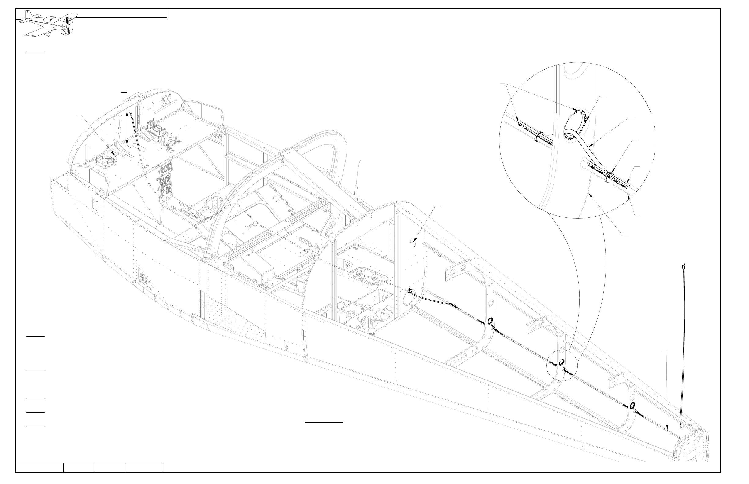
Step 1: Position the ES-00301 on the aft-most lightening hole as shown in Figure 1, then match-drill #30 the rivet hole into the
VS-1205.
Step 2: Rivet the ES-00301 to the VS-1205 with the hardware shown in Figure 1. A small dab of superglue can be used to hold the
washer to the bottom of the VS-1205 if necessary.
Step 3: Rivet the F-00205 Shim and the nutplate onto the VS-1205 as shown in Figure 1.
Step 4: Temporarily secure the F-00206 and AV-532L Antenna on to the VS-1205 with the fasteners shown in Figure 1.
Step 5: Mark the longitudinal position of the AV-532L Antenna elements on the VS-1201 as
shown in Figure 1.
Step 6: Measure the vertical height of the AV-532L Antenna element
above the top edge of the VS-1201 as shown in Figure 1 and record
the value.
Remove the AV-532L from the V-Stab Assembly.
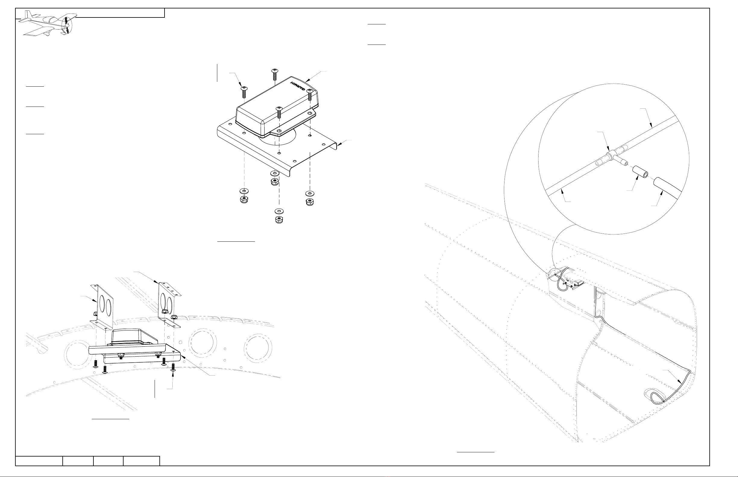
Step 7: Temporarily install the VS-1213 onto the V-Stab
Assembly with #6 screws as shown in Figure 1.
Step 8: Transfer the positioning marks made in Step 5 from
the VS-1201 to the VS-1213.
Measure and mark the height of the AV-532L Antenna
element onto the VS-1213.
NOTE: The notch cut in Step 9 should be smoothly
radiused at the top (approx 1/8 in. [1.6 mm] radius).
Step 9: Remove the VS-1213 from the V-Stab
Assembly and cut a notch in the VS-1213 from the
antenna element positioning marks, down to the
lower edge of the VS-1213.
Ensure adequate clearance around the antenna
elements to allow for vibration of the elements
as shown in the Detail View in Figure 1.
F-00205 SHIM
2X CCR264SS-3-2
K1000-3
VS-1213
VS-1201
VS-1213
VS-1201
AV-532L
NOTCH FOR 1/32-1/16 [.8-1.6 mm]
CLEARANCE ALL SIDES
FIGURE 1: NOTCHING THE FAIRING
VS-1205
42PiS-05RV-12iS001/19/19 PAGE:REVISION:DATE:
VAN'S AIRCRAFT, INC.
PLASTIC TIE-WRAP 5.5"
2X PLASTIC TIE-WRAP 5.5"
F-00204
NAV ANTENNA CONDUIT
Step 1: Drill #19 a hole in the VS-1208 Rib at the location shown in Figure 1.
Step 2: Fabricate the F-00204 Nav Antenna Conduit by cutting a piece of NT Duct 5/8 to a length of of 44 1/2 in. [113 cm].
Step 3: Route the F-00204 through the aft-most set of lightening holes in the ribs of the V-Stab Assembly. See Figure 2.
Step 4: Secure the F-00204 to the ES-00301 on the top of the V-Stab Assembly.
The F-00204 should extend approximately 1/4 in. [6.4 mm] past the ES-00301. See Figure 2.
Step 5: Secure the bottom of the F-00204 to the VS-1208 using two crossing tie-wraps through the hole in the VS-1208 as
shown in Figure 2.
FIGURE 2: INSTALLING THE NAV ANTENNA CONDUIT
V-STAB ASSEMBLY
DRILL #19
5/8 [15.9 mm]
FROM EDGE
VS-1208
FIGURE 1: DRILLING THE V-STAB RIB
LEFT
UP
FWD
VAN'S AIRCRAFT, INC.
PAGE: REVISION: DATE: 01/19/190RV-12iS42PiS-06
PILOT DRILL #30
THEN STEP-DRILL 5/8
Step 1: Drill #30 a hole in the F-1278 Top Skin at the location shown in Figure 1.
Step 2: Use a step drill to enlarge the #30 hole in the F-1278 to 5/8.
Step 3: Install the snap bushing into the F-1278 as shown in Figure 1.
Step 4: Cut strips of MS21266 Grommet to the length shown in Figure 2 to fabricate 8 of the F-1257B Cable Anti-Chafe Strips.
F-1278
FIGURE 1: DRILLING THE TAILCONE
SB625-7
FIGURE 2: FABRICATING THE F-1257B
(QTY 8 REQD)
SCALE 1 TO 1
3 [76.2 mm]
MS21266
42PiS-07RV-12iS001/19/19 PAGE:REVISION:DATE:
VAN'S AIRCRAFT, INC.
AV-532L CABLE
F-1238-R
DRILL #30,
SECURE AV-532L CABLE
WITH PLASTIC TIE-WRAP 4"
F-1211A
APPROX.
1/2 [12.5 mm]
PLASTIC
TIE-WRAP 4"
F-1257B
F-1281-L
F-1281-R STIFFENER
Step 1: Drill #30 a hole in the center of the inboard flange of the F-1238-R as the location shown in Figure 1.
NOTE: When positioning and securing the AV-532L cable in the following steps, ensure that the AV-532L cable is not
rubbing on the sharp edge of of the F-1279-R Upper Right Skin stiffener, and is clear of all control cables.
Step 2: Route the AV-532L cable through the snap bushing in the F-1278.
Step 3: With the AV-532L cable extending outside the tailcone as shown, secure the AV-532L cable to the F-1238-R with a
tie-wrap. See Figure 1.
Step 4: Route the AV-532L cable from the F-1238-R to the stiffener of the F-1281-R Lower Skin. Cover the stiffener edge with a
F-1257B where the cable enters the stiffener.
Step 5: Secure the AV-532L cable and F-1257B to the stiffener of the F-1281-R with a tie-wrap
as shown in Figure 1.
FIGURE 1: SECURING THE AV-532L CABLE
54 [137.2 CM]
(PAST SURFACE OF F-1278)
F-1279-R STIFFENER
VAN'S AIRCRAFT, INC.
PAGE: REVISION: DATE: 01/19/190RV-12iS42PiS-08
AV-532L CABLE
F-1257B TYP.
F-1281-R STIFFENER
F-1209-R
FUSELAGE FRAME
F-00217
TYP.
PLASTIC
TIE-WRAP 4"
TYP.
DAB OF RTV OR
FUEL TANK
SEALANT
TYP.
Step 1: Route the AV-532L cable up the F-1281-R stiffener, passing through the lightening holes in each of each fuselage frame
as shown in Figure 1.
NOTE: Airframes with dual pass through holes in the F-01202B-1 should route the AV-532L cable through the foremost
hole.
Step 2: Following the path of the WH-00136 forward of the
F-01207C-L, route the AV-532L cable forward through the airframe
and up through the wire pass-through hole in the F-01202B-1 as
shown in Figure 1.
Step 3: Install the F-1257Bs onto the F-1281-R stiffener to
protect the AV-532L cable at all points where the cable
enters/exits the stiffener. See the Detail View of Figure 1.
Step 4: Cut 3 strips of MS21266 grommet to 4 3/8 in. [111.1mm] to fabricate the F-00217s.
Step 5: Install the F-00217s into the fuselage frames as shown in the Detail View of Figure 1.
Step 6: Once the entire AV-532L cable has been routed and positioned correctly, secure the
AV-532L cable to the F-1281-R stiffener with tie-wraps as shown.
FIGURE 1: ROUTING THE AV-532L CABLE
F-01202B-1
F-1207C-L
AV-532L CABLE
6 [152.4 mm]
42PiS-09RV-12iS001/19/19 PAGE:REVISION:DATE:
VAN'S AIRCRAFT, INC.
FIGURE 1: ROUTING THE AV-532L CABLE
THROUGH THE V-STAB ASSEMBLY
AV-532L NUT
AV-532L LOCK WASHER
MS21919DG6
AV-532L CABLE
F-00204
AN525-10R8
Step 1: Reinstall the V-Stab Assembly to the airframe, while simultaneously routing the AV-532L cable
through the F-00204. See Figure 1.
A piece of safety wire passed through the F-00204 prior to reassembly can be used to pull the
AV-532L cable up through the F-00204 if necessary.
Step 2: Connect the ring terminals on the end of the AV-532L cable onto the studs of the AV-532L
antenna with the included fasteners as shown in Figure 2.
Step 3: Clasp the cushion clamp over the AV-532L cable and secure the cushion clamp to t he F-00205
relieving any strain on the ring terminals. See Figure 2.
Step 4: Reinstall the VS-1213 onto the V-stab assembly as shown in Figure 3.
FIGURE 2: CONNECTING THE AV-532L CABLE
AV-532L ANTENNA
F-00205 VS-1213
12X AN507C632R6
V-STAB ASSEMBLY
V-STAB
ASSEMBLY
FIGURE 3: INSTALLING THE V-STAB FAIRING
VAN'S AIRCRAFT, INC.
PAGE: REVISION: DATE: 01/19/190RV-12iS42PiS-10
F PLASTIC TEE
F-00012
AFT PITOT LINE
F-00014
F-00012
AFT PITOT LINE
GMU 11
4X
AN526C632R8
AN960C6
MS21044C06
F-00142
4X
AN526C632R6
AN960C6
MS21044C06
F-00009-R
F-00009-L
NOTE: Never use magnetic tipped screwdrivers or
other magnetic objects when working with hardware
near the GMU 11. The GMU 11 is very sensitive and
may be influenced by any magnetized hardware.
Step 1: Install the GMU 11 to the F-00142 GMU 11 Attach
Plate as shown in Figure 1.
Step 2: Mount the F-00142 to the F-00009-L & -R ADAHRS
Brackets in the upper tailcone skins as shown in Figure 2.
Ensure the GMU 11 connector is facing aft.
Step 3: Connect the 9-pin d-sub connector labeled
"MAGNETOMETER" from the WH-00136 to the GMU 11.
F-000142
FIGURE 1: GMU 11 INSTALLATION
FIGURE 2: MOUNTING THE GMU 11
Step 4: If necessary, disconnect and discard the F-00013 Static Line Tee-ADAHRS from the F Plastic Tee and F-00014 Static Line
Tee Upsize. See Section 10iS/U and the detail view in Figure 3.
Step 5: Connect the Aft Pitot Line to the F Plastic Tee using the F-00014 as described in Section 10iS/U. If necessary, trim the Aft
Pitot Line as required to prevent interference or chafing on the surrounding structure.
Ensure there are no kinks in the Aft Pitot Line. See Section 10iS/U and the detail view in Figure 3.
FIGURE 3: CONNECTING THE AFT PITOT LINE