Model lCi Operation Manual
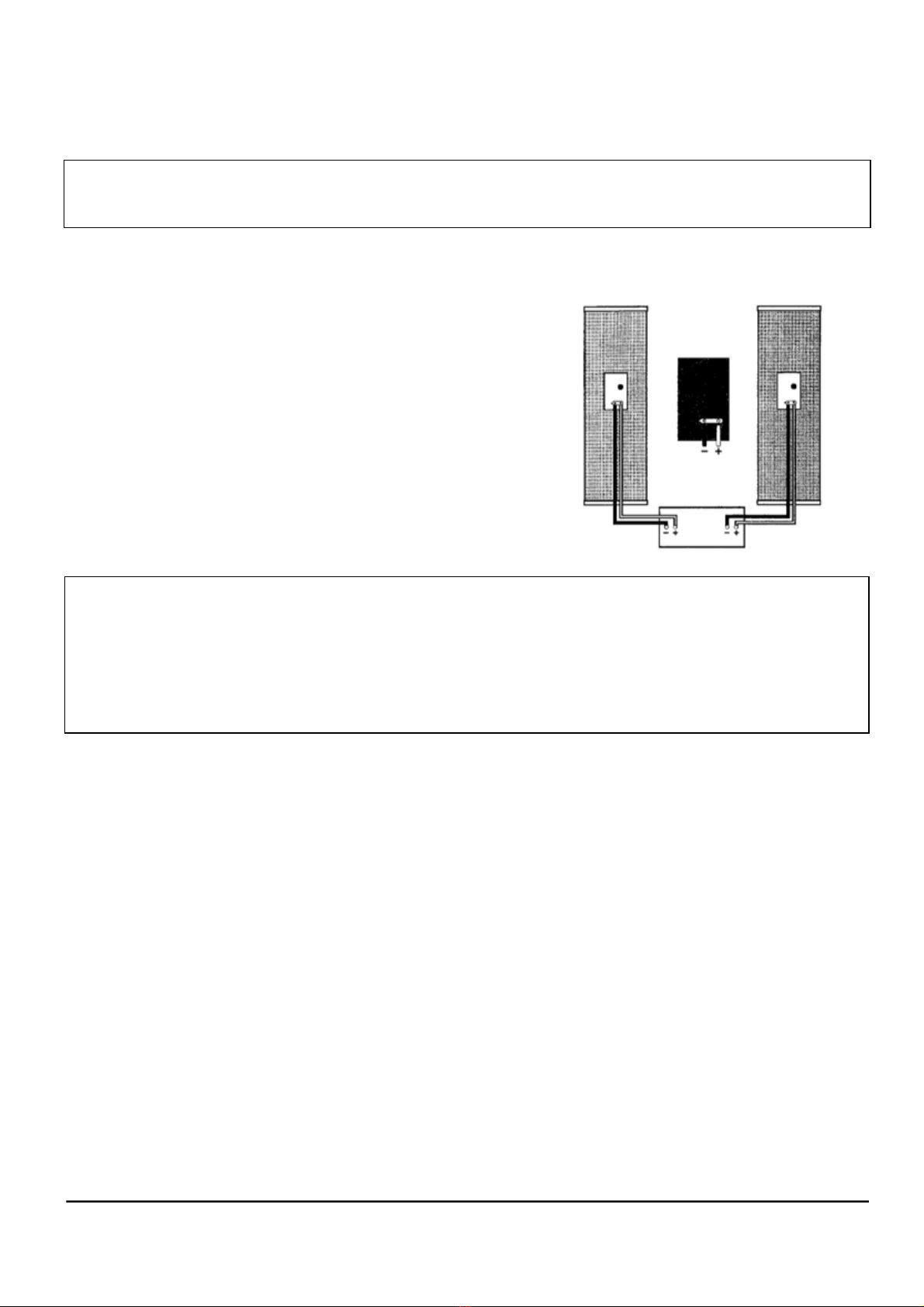
The 1Ci is not magnetically shielded and
should be positioned at least 10 inches
away from a direct view television set
.
amount forward or backward.
Third dimensions placement reduces the interaction of
the speakers with the room to an absolute minimum but
can create aesthetic or room function problems due to the
speakers and listening position being so far out into the
room. (The lower the odd number used to divide the dimen-
sions the lower the interaction between the speakers and
the room.)
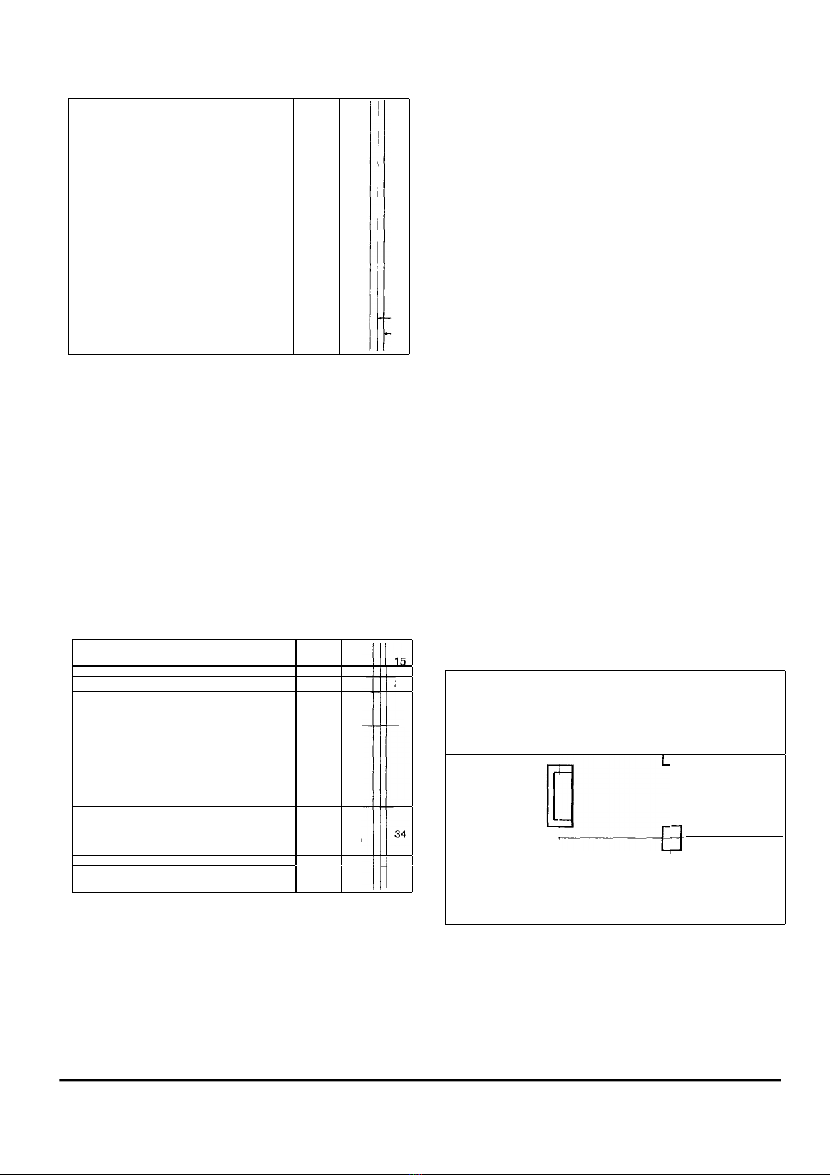
ACOUSTICAL CENTER
The Model 1Ci's acoustical center is the physical center
of the loudspeaker. In a perfect rectangular room with
absolutely rigid walls and no doors or windows, the
acoustical center of the loudspeaker would be placed
exactly at the point where the two dimensions intersect to
realize the full benefits of odd dimensions or third
dimensions placement. In a real room, the actual best
placement may vary from the intersection by as much as
two inches or so. Fine-tuning the placement by moving the
speakers a couple of inches off the odd dimension
intersections takes these real-world conditions into
account.
You should not use any placements that would place
the acoustical center of the loudspeaker the same distance
from the rear and side walls. The measurement from the
center of the loudspeaker to the two walls should differ by
at least two inches. Odd dimension intersections that are
within two inches of the same distance from both the side
and rear wall should not be used.
SPEAKER)TOE-IN
)
The#degree#of#toe-in#can#affect#the#imaging#and#
response
#
characteristics#of#the#speakers.
#
In#most
#
rooms,
#
the#
speakers#will#sound#best#with#some#toe-in.#Speakers#that
#
are#
placed#close#to#the#side#walls#or#in#rooms#with#very#reflec-#
tive#side#walls#may#require#additional#toe-in#to#avoid#a#con-#
fused#image#and/or#a#forward#midrange#and#treble.#
If#the#speakers#seem#to#need#an#excessive#amount#of#
toe-in#to#image#properly#or#achieve#good#center#fill,#there#
may#be#a#problem#with#the#set-up#or#connection#of#the#
speakers
#
or#some#part
#
of#the#system#may#not#be#functioning#
as#intended.#To#determine#why#the#speakers#require#exces-#
sive#toe-in,#check
#
all#your#speaker
#
wire#connections
#
for#cor-#
rect#phase#and#verify#that#the#electrical#components#in#the#
system#are#connected#and#functioning#properly.#
ACOUSTIC TREATMENTS
If the speakers are close to the side walls and you hear
a brightness in the midrange/treble or a problem with the
imaging that toeing-in the speakers does not help, some
sound absorbent material should be mounted on the side
walls to control reflections.
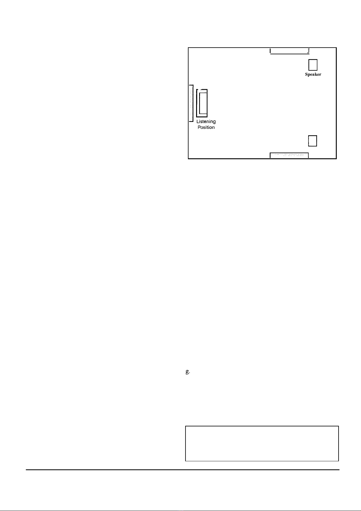
To determine where the sound absorbent material
should be placed, imagine that the walls are mirrors and
mount the material on the walls where you would see the
reflections of the speakers when you are in your normal lis-
tening position. Before you actually mount anything on the
side walls, experiment with a folded natural-fiber blanket to
verify the positioning of the material and that you get the
desired results.
If your listening position is close to the wall behind
you, mount some sound absorbent material, such as a hang-
ing tapestry, directly behind your head. As with the material
for the side walls, experiment with a folded natural-fiber
blanket to verify the results before you acquire or mount
the material.
Bass problems that cannot be corrected with place-
ment adjustments may be helped by the addition of bass
traps or other bass control devices. Follow the instructions
of the bass control devices as to their proper set-up and
placement to correct the problems you are experiencing.
HELPFUL
HINTS
a. To try the speakers on different walls, set your equipment
in the middle of the room so the speaker cables can reach
each possible location.
b. When you change the placement of the speakers, listen to
several different pieces of music before judging the results
of the change.
c. If you set the speakers on a wood floor, place a coin under
each stand spike or use P4-20 thread carriage bolts in place
of the spikes to prevent damage to the floor. Carriage bolts
have rounded heads that will not put holes in the floor.
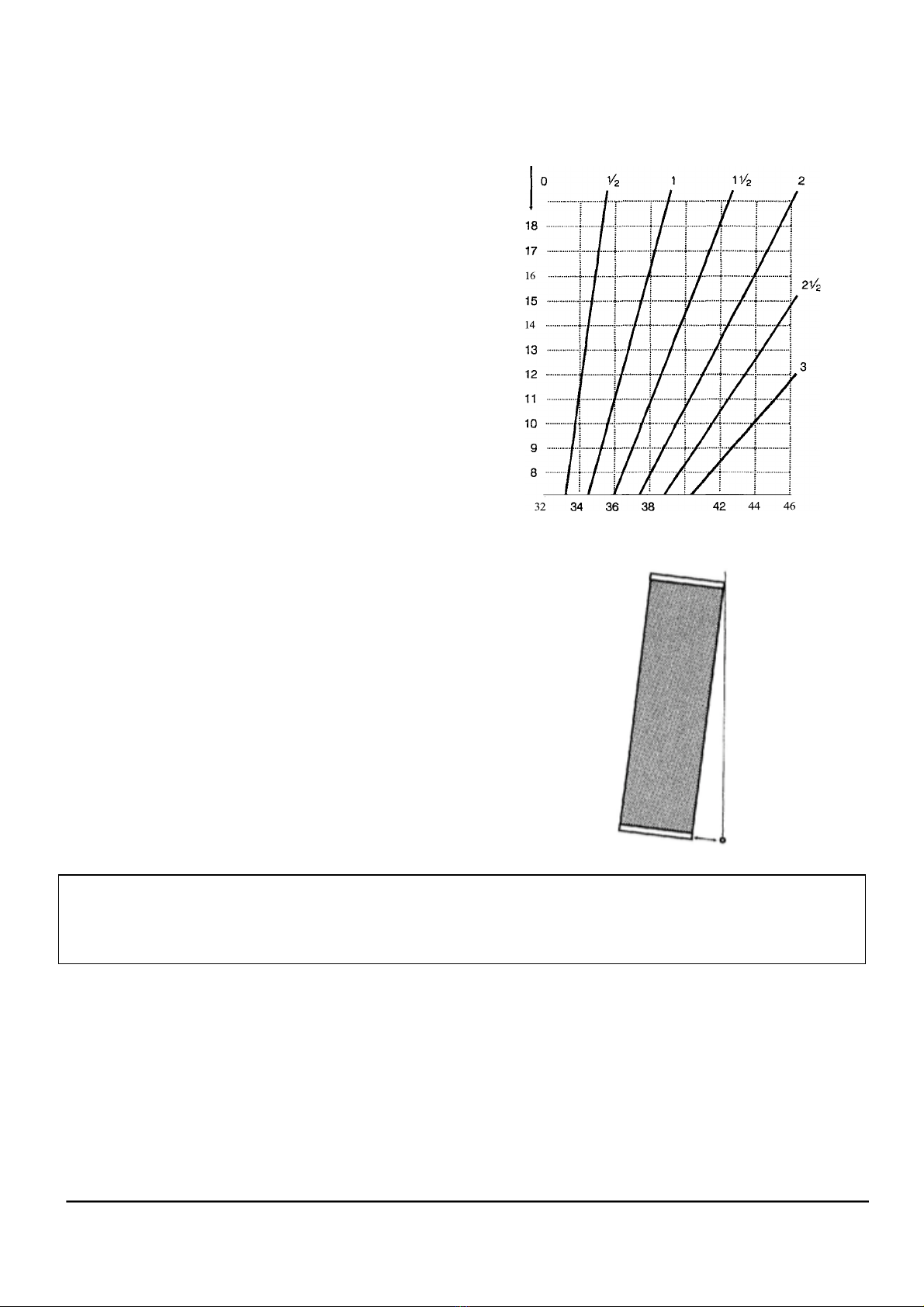
d. Keep the spikes or carriage bolts on the bottom of the
stands as short as possible while still accomplishing the
proper vertical angle for your listening height and distance.
Excessive length will reduce the stability of the speakers.
e. When you have discovered the optimum speaker position-
ing in your room, mark it with tape so you can move the
speakers to vacuum without loosing your placement.
f. If the bass is ill-defined in your room regardless of where
you place the speakers, check your windows for loose panes
of glass. Loose glass will vibrate and can seriously impair
the low frequency detail of the system.
Keep notes on the sound of different placements you try.
It is easy to get mixed-up and forget which placement
sounded the best.
h. Don't over-analyze the sound of each placement. When the
sound is right, it will be obvious.
Speaker