Vanward GD4838S-G User manual

1
MODEL : # GD4838S-G
Distributor’s: Vanston Inc.
WARNING
For Outdoor Use Only
DANGER
If you smell gas:
1. Shut off gas to the
appliance.
2. Extinguish any open flames.
3. Open the lid.
4. If the odor continues,keep
away from the appliance and
immediately call your gas
supplier or fire department.
WARNING
1. Do not store or use
gasoline or other
flammable vapors and
liquids in the vicinity of
this or any other appliance.
2 . An LP tank not connected
for use should not be
stored in the vicinity of
this or any other
appliance.
WARNING
Improper installation,
adjustment, alteration, service
or maintenance can cause
injury or property damage.
Read this
instruction manual
thoroughly before installing or
servicing this equipment.

2
TABLE OF CONTENTS
Safety Information
Package Contents
Hardware Contents
Preparation
Assembly Instructions
Installation Instructions
Operating Instructions
Care and Maintenance
Troubleshooting
Warranty
3
5
7
7
8
19
23
27
32
34

SAFETY INFORMATION
3
Please read and understand this entire manual before attempting to assemble, operate or
install the product. If you have any questions regarding the product, please call customer
service at 1-800-963-0211, 8 a.m-6 p.m., EST, Monday-Thursday, 8 a.m.-5 p.m., EST, Friday.
The installation of this appliance must conform with local codes or , in the absence of
local codes,
with the National Fuel Gas Code, ANSI Z 221.3/NFPA 54.
This grill is intended for use outdoors and should not be used in a building, garage or any
other enclosed or
covered area.
This outdoor grill is not intended for installation in or on recreation vehicles and/or boats.
A minimum clearance of 36 inches from combustible constructions to the sides of the grill and 36
inches from the back of the grill to combustible constructions must be maintained. This outdoor
cooking gas appliance must not be placed under overhead combustible
construction.
The use of an electrical source requires that when installed, the grill must be electrically
grounded in accordance with local codes or in the absence of local codes, with ANSI/NFPA 70, or the
Canadian Electrical Code, CSA C22.1. Keep electrical supply cords and the fuel supply
hose away
from heated surfaces.
Inspect the hoses before each use for excessive abrasion or wear, or cuts that may affect
safe operation of the grill. If there is evidence of excessive abrasion or wear, or the fact that
the hose is cut, it must be replaced prior to the grill being put into operation. The
replacement hose assembly must be those specified by the manufacturer.
Keep your grill in an area clear and free from combustible materials, gasoline and other
flammable vapors and liquids.
DO NOT obstruct the flow of combustion and ventilation air to this appliance.
Keep the ventilation openings of the tank enclosure free and clear of debris.
Check all gas connections for leaks with a soapy water solution and brush. Never use an
open flame to check for leaks.
Never use charcoal in the grill.
Never use the grill in windy areas.
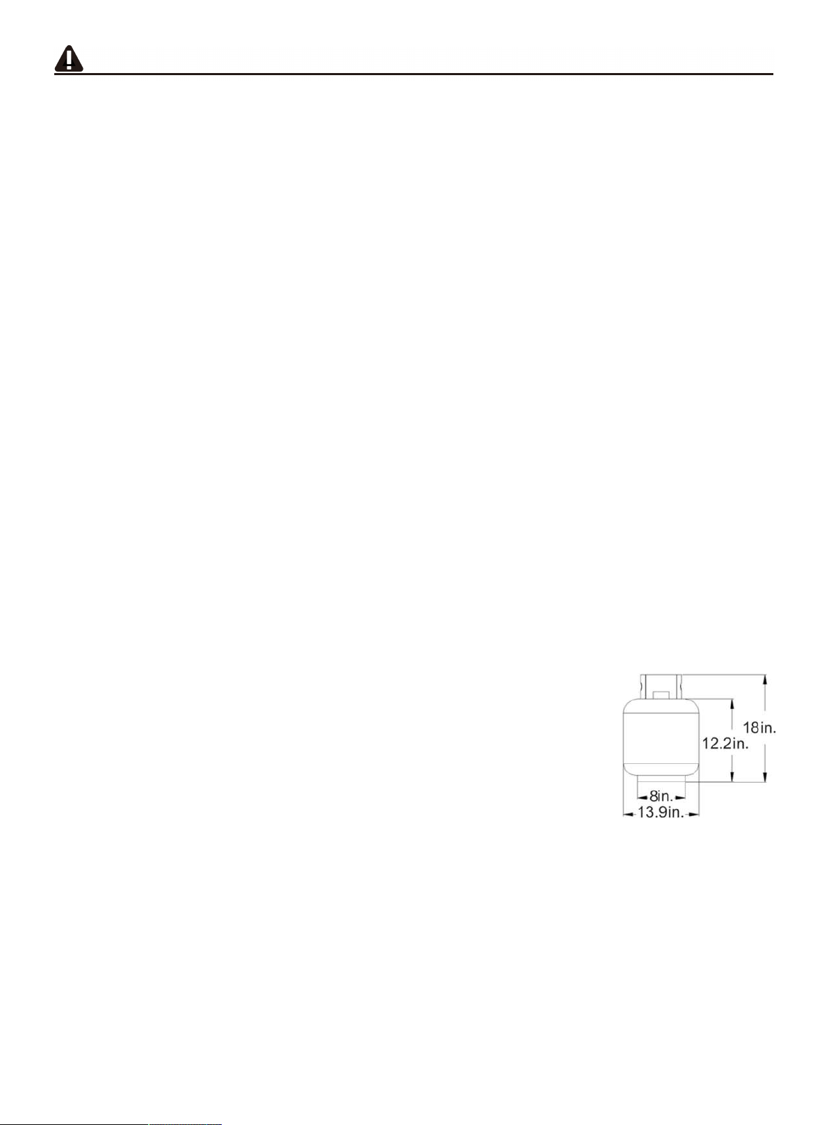
Only a 20 lb. LP-gas cylinder is allowed. The cylinder must be
constructed and marked in accordance with the Specifications for LP
Gas Cylinders of the U.S.Department of Transportation (D.O.T.) or the
National Standard of Canada, CAN/CSA-B339, Cylinders, Spheres and
Tubes for Transportation of Dangerous Goods; and Commission.
Dimensions for a 20 lb. LP-Gas cylinder are:
Never use the grill without the drip tray installed and hung under the burner box. Without the
drip tray, hot grease and debris could leak downward and produce a fire hazard.
Use only the gas pressure regulator supplied with this appliance. This regulator is set for an
outlet pressure of 11.0 wc.
The cylinder used must include a collar to protect the cylinder valve.
Do not store a spare LP-gas cylinder under or near this appliance.
Never fill the cylinder beyond 80 percent full.
The regulator and hose assembly must be routed through the left leg assembly. Regulator
must be locked with regulator hose lock before connect with LP tank. See page 18 for
detailed assembly instructions.

SAFETY INFORMATION
4
DANGER: If the information in above is not followed exactly, a fire causing death
or serious injury may occur.
The outdoor cooking gas appliance must be isolated from the gas supply piping system
by closing its individual manual shutoff valve during any pressure testing of the gas
supply system at test pressures equal to or less than 1/2 PSI (3.5 KPa).
CALIFORNIA PROPOSITION 65 WARNING: The burning of gas cooking fuel generates
some byproducts which are on the list of substances known by the State of California to
cause cancer, reproductive harm, or other birth defects. To reduce exposure to these
substances, always operate this unit according to the use and care manual, ensuring you
provide good ventilation when cooking with gas.
IMPORTANT: We urge you to read this manual carefully and follow
the recommendations enclosed. This will ensure you receive the
most enjoyable and trouble-free operation of your new gas grill. We
also advise you retain this manual for future reference.
WARNING: Your grill has been designed to operate using only the
gas specified by the manufacturer on the rating plate. Do not attempt to
operate your grill with other gases. Failure to follow this warning could
lead to a fire hazard and bodily harm and will void your warranty.
WARNING: Make certain your LP (propane) tank is filled by a reputable
propane dealer. An incorrectly filled or overfilled LP tank can be
dangerous. An overfilled tank combined with the warming of the LP tank
(a hot summer day, tank left in the sun, etc.) can cause LP gas to be
released by the pressure relief valve on the tank since the temperature
increase causes the propane to expand. LP gas released from the tank is
flammable and can be explosive. Refer to your Owner's Manual for more
information concerning filling your LP tank.
The installer must hand the instructions to the consumer and the
consumer should retain them for future reference.
If the outdoor cooking gas appliance is not in use, the gas must be
turned off at the supply cylinder(s). Storage of an outdoor cooking
gas appliance indoors is permissible only if the cylinder(s) is (are)
disconnected and removed from the outdoor cooking gas appliance.
Cylinders must be stored outdoors out of the reach of children and
must not be stored in a building, garage, or any other enclosed area.

Package Contents
5

Package Contents
6
1
2
3
4
5
6
7
8
9
10
11
Bottom Panel
Left Leg Assembly
Front Panel
1
2
2
1
1
1
1
1
1
2
1
20
23
15
16
17
18
19
21
22
Part Part
24
12 1
Right Leg Assembly
25
Knob
13 1
26
Knob Bezel
Stay Rod for
condiment tray
Condiment Tray
Drip tray bracket right
Drip tray bracket left
Axle
Wheel
Cylinder stop rod
Gas Cylinder Safety
Stop
Firebox and Hood
Assembly
Right Side Burner
Table
Side Burner
Side Burner holder
Side Burner Grid
Heat Tent
Cooking Grate
Warming Rack
Drip Tray
Grease Cup
Regulator Hose Lock
27
Matchstick Holder
Assy
14 Left Side Table 28
Side Table Handle

7
Hardware Contents
PREPARATION
Before beginning assembly of product, make sure all parts are
present. Compare parts with package contents list and hardware
contents list. If any part is missing or damaged, do not attempt to
assemble the product.
Tools required for assembly (not included): Phillips Screwdriver, Wrench.

8
1. Attach the four legs to bottom panel
Using 2-M6x12 screws, secure left leg assembly (part 2) to bottom panel (part 1) and
right leg assembly (part 3) with corresponding screws, Insert the stay rod for.
condiment tray (part 5) into the mounting holes on left leg assembly and right leg
assembly. Assemble 2 additional legs in same manner (see illustration below).
2. Install the Front Panel
Insert the corresponding M6x12 screws with M6 lock washers into the pre drilled
holes in lower portion of the left and right legs located at the front of the cart. Do not
tighten screws. Line up the slots in the front panel (part 4) to the screws. Slide the
front panel into place. Tighten the 4 screws.

9
3. Install the Condiment Tray
Insert 4 M6X12 screws with 4 M6 lock washers into the pre drilled holes in the upper
portion of the front legs of the cart. Do not tighten screws. Line up the slotted holes in
the condiment tray (part 6) to the screws. Slide the condiment tray into place. Tighten
the screws.
4. Install the Wheel
Insert the axle (part 9) into the wheel (part 10) and then into axle mat. Insert the axle
into the predrilled hole located on the right front leg of the cart (see illustration below).
The axle will then insert into coordinating hole in the cart leg at the back of the cart.
Insert the additional wheel on the axle on the back side of the cart. Insert the axle
washer on the axle and secure with the M6 lock nut. There is a small wrench included.

10
5. Install left and right drip tray brackets
Lock the drip tray bracket left (part 8) and drip tray bracket right (part 7) into the
mounting hole at left and right leg assembly with corresponding M4x8 screws.
6. Install the cylinder stop rod and gas cylinder safety stop
Place the cylinder stop rod (part 11) in the mounting hole at condiment tray and predrill
hole in bottom panel. Place the gas cylinder safety stop (part 12) in the predrilled holes
in bottom panel (see illustration below). Insert R pins into the predrilled hole at the tip
of the cylinder stop rod inserted through hole in condiment tray (see illustration below).

11
7. Install the R pin at Cylinder stop rod and Gas Cylinder Safety Stop
Lay cart on its side. Install three R pins in the pre drilled holes in the tips of the cylinder
stop rod (part 11) and gas cylinder safety stop (part 12). Set cart upright.
8. Install the firebox and hood assembly
Place the knob (part 17) on the valve stem (see illustration below). Set the firebox and
hood assembly (part 13) on top of the cart panel. Secure the firebox and hood
assembly with 2 M6x16 screws and 2 M6 washers at the top of each leg of the cart
(see illustration below).

12
9. Install side table handle
Unscrew the pre-installed screws on the handle, then put the screws through the holes on the side of
side table, connect them to the handle (part 28), and tighten the screws (2).
10. Install the left side table
Line up the holes in the left side table (part 14) with the pre-installed screws on left
side of the firebox and hood assembly. Slide left side table into place over the screws.
Tighten the pre-installed screws to secure the side table.

13
11. Install the right side burner table
Line up the holes in the right side table (part 15) with the pre-installed screws on right
side of firebox and hood assembly. Slide right side table into place over the screws.
Tighten the pre-installed screws to secure the side table.
12. Install the knob bezel and side burner gas line
As shown in figure below, line up the holes in the side burner valve bracket to the
holes in the back side of the right side table front panel. Hold in place with one hand.
On the front side of the side table front panel line up the holes of the bezel (part 16)
with the holes in the front panel. Hold the bezel with the thumb of the hand holding the
side burner valve in place. Using free hand insert M4x8 screws into holes in bezel
securing bezel and side burner control valve. Tighten screws.

14
13. Install side burner
Place side burner through the hole in the top of the right side table. Insert the open end
of side burner (part 18) over the outlet end of side burner valve (see illustration below).
Center the hole in the side burner over the outlet on the control valve (it is ok that the
open part of the side burner is not sealed). Line up the holes in the side burner bracket
to the holes in the top of the side table locking the side burner at the mounting hole of
right side burner with corresponding screws. Mount the knob (part 17) on the side
burner valve stem.
14. Install the side burner bracket
Line up the side burner bracket (part 19) to the pre drilled holes in side table, using 2-M4x8 screws.
Secure the bracket to the side table (see illustration below).

15
15. Install the side burner grate
Insert side burner grate (part 20) over the side burner making sure the tabs line up with
corresponding holes (see illustration below).
16. Install heat tents
Place the 4 heat tents (part 21) over each burner inside the firebox. Vented end of heat tent is
placed toward the back of the firebox (see illustration below).

16
17. Install the cooking grate
Place the cast iron cooking grates (part 22) into the firebox. Grates are porcelain
coated. Seasoning is not required.
18. Install the warming rack
Insert warming rack (part 23) making sure the tabs on the warming rack fit into the
pre-drilled holes in the firebox (see illustration below).

17
19. Install the drip tray and grease cup
Insert the drip tray (part 24) into the drip tray brackets from the back of the grill. Insert
the grease cup (part 25) into the brackets on drip tray (see illustration below).
20. Secure regulator hose
Using clamp (part 26) and corresponding screw, secure the regulator hose to the right
front leg of the cart using the pre drilled hole. This is a safety feature to make sure the
regulator hose does not get too close to the drip tray (see illustration below for hole
location).

18
21. Install matchstick holder assy. and igniter battery
Locate screw at the 2/3 position of back left leg of cart. Do not tighten screw. Hang the
single loop end of matchstick holder (part 27) onto the screw. You may also hang the
top loop on the other end of the matchstick holder over the same screw (see illustration
below). This is a safety feature for use when lighting with a standard match. Please
use with caution.
Locate igniter button on front panel of grill. Unscrew the igniter button. Place AA
battery inside the igniter negative end first. Make sure the spring is located inside the
rubber boot of the igniter button. Screw igniter button back into place (see illustration
below).
22. Install gas tank
Place 20 lb. LP tank (not
included) into round opening in
the bottom of cart. Secure tank
using gas cylinder safety stop
(P).
Connect regulator to tank and
tighten
by hand. Your grill is now
ready for use.

19
INCORRECT REGULATOR ASSEMBLY
The regulator and hose should not be routed through the gap between the bottom
of firebox and the top of cart. Incorrect assembly will result in loss of warranty.
Incorrect assembly may cause gas leakage, fire and severe bodily harm. The
regulator and hose assembly must be routed through the hole of the left side
panel into the cart.
CHECK FOR SPARKS
After grill assembly is completed, test the ignition system with the GAS OFF.
Check to make sure all igniters spark while pressing the ignition button.
For Portable LP-Gas Connection
The cabinet has an opening in the bottom panel that allows a 20 lb. gas tank bottom
flange to drop into place (tank not included).This will help to lock the tank in place. After
positioning the tank in the opening, lift up the gas cylinder safety stop to lock the tank
(Fig. 21). Use only 20 lb. gas tank (See LP Gas Safety Requirements for additional
information). As shown in Fig.22, it is unsafe to operate the grill if the gas tank is not
vertical.

20
Hand Wheel
Type I
Valve
External
Thread
Fig.24
Thermally
Sensitive Nut
Propane
Regulator
The propane tank valve connection supplied with this grill incorporates four important
safe guards: Hand Assembly, Hand Disassembly, Excess Flow Control and
Temperature-Activated Shut-Off.
a.
Hand Assembly:
1.
Make certain the tank valve and all the appliance valves are in the “OFF” position.
2.
When connecting the regulator valve assembly to the tank, turn the
large plastic nut clockwise until it stops.
3.
Gas will not flow unless the plastic nut is completely connected.
4.
HAND TIGHTEN ONLY.
WARNING: The Type I connective coupling (see Fig.24)
supplied with your grill
must not be replaced with a diff
erent type of grill/tank connection system. Removal
will result in loss of warranty, gas leakage, fire and severe bodily harm.
Table of contents
Other Vanward Grill manuals
Popular Grill manuals by other brands

Patton
Patton Kamado 16 Black Customer's operating and assembly instructions

Masterbuilt
Masterbuilt 20150108 Assembly, care & use manual

Outback
Outback Excel 100 Assembly and operating instructions

Power Smokeless Grill
Power Smokeless Grill GR-200 owner's manual

Johnson
Johnson Tom Instructions for use

Pit Boss
Pit Boss PB700FBW2 Assembly and operation instructions