CONTENTS'
Page
SECTION 1 INTRODUCTION
1. 1
General
1-1
1
.2
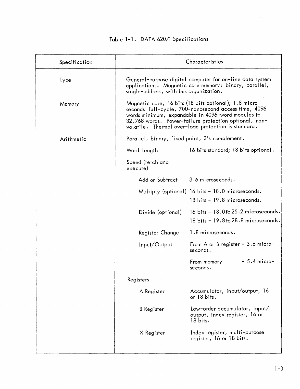
Specifications
1-2
1.3
Use
of this Manual
1-6
SECTION 2
SYSTEM
DESCRIPTION
2.
1 Computer Organization 2-1
2.2
Computer Word Formats
2-6
2.3
Computer Options 2-11
SECTION 3 OPERATIONAL INSTRUCTIONS
3.
1
General
3-1
3.2
Sing Ie-Word Instructions 3-1
3.3
Double-Word Instructions 3-31
SECTION 4 INPUT/OUTPUT
SYSTEM
4.1 Introducti
on
4-1
4.2
Organizati
on
4-1
4.3
Program Control Functions
4-3
4.4
Optional Automatic Control Functions 4-11