VARIZOOM Cinema Pro-K5 User manual

Cinema Pro-K5
Operations Manual

BEFORE YOU START, READ THESE WARNINGS
1) NEVER PLUG POWER DEVICES OTHER THAN THOSE SUPPLIED BY
VARIZOOM INTO THE SYSTEM. ONLY USE VARIZOOM POWER SOURCES
AND CABLES. USING DIFFERENT POWER COMPONENTS CAN LEAD TO
SEVERE DAMAGE TO THE HEAD AND EVEN THE CAMERA. THIS TYPE
OF DAMAGE IS NOT COVERED UNDER WARRANTY.
2) DO NOT MODIFY THE SUPPLIED CABLES OR ATTEMPT TO
DISASSEMBLE THE HEAD.
3) LENS CONTROL CABLES MUST ONLY BE PLUGGED INTO THE
SPECIFIED INPUT JACK ON THE LENS ITSELF –NEVER PLUG A 12-PIN
CONNECTOR ON A VARIZOOM LENS CONTROL CABLE INTO THE 12PIN
JACK ON THE CAMERA BODY. WHEN IN DOUBT, CONSULT VARIZOOM
OR YOUR LENS MANUAL.
4) THE ADVANCED CONTROLLER DOES NOT REQUIRE SEPARATE POWER,
IT RECEIVES POWER THROUGH THE GREEN-CODED CONTROL CABLE
THAT CONNECTS TO THE HEAD. THE “AUX” POWER JACK ON THE
ADVANCED CONTROLLER IS ONLY UTILIZED IN WIRELESS
CONFIGURATIONS AND SHOULD ONLY BE CONNECTED TO A
VARIZOOM POWER SUPPLY.
5) DO NOT OPERATE THE HEAD WITH AN UNBALANCED LOAD (i.e., with
the camera’s weight extremely off-center either horizontally or
vertically).
6) DO NOT GET THE SYSTEM WET –IT IS NOT WATERPROOF.
7) ALWAYS MAKE SURE YOUR LENS AND POWER CABLES HAVE ENOUGH
SLACK RUNNING THROUGH THE TILT AXIS TO PREVENT TWISTING
AND TEARING OF THE CABLES.
8) MAKE SURE YOUR LENS CLEARS THE BASE OF THE HEAD WHEN
TILTING. IF THE LENS DOES NOT CLEAR THE BASE, SET SOFT LIMITS
(SECTION 7) TO PREVENT THE LENS FROM STRIKING THE BASE OF
THE HEAD WHEN TILTING.
9) WHEN USING THE CP JR’s ONBOARD LENS CONTROLS TO CONTROL
YOUR CAMERA, ALWAYS POWER THE CAMERA UP LAST. OTHERWISE,
THE RECORD START/STOP FEATURE MAY FALL OUT OF SYNC. TO
AVOID THIS ISSUE, JUST MAKE SURE TO CONNECT XLR POWER TO
THE HEAD BEFORE YOU TURN YOUR CAMERA ON.

General Description
The Cinema Pro is a mid-size, two axis motion control head. It has a wide
variety of operating modes: manual operation from joystick, optional hand wheels or
pan bars control, motion control style record and playback, “go to mark” preset
framing, intervalometer operation and can operate as a slave to Kuper Node
motion control*. It also is capable of providing motion data for virtual set operation.
The Cinema Pro Advanced Controller gives the user all input and programming
capabilities and has a joystick for pan & tilt control. The Advanced Controller also
works in concert with two optional control input devices: Pan Bars for broadcast-style
operation or Hand Wheels for cinema-style operation.
The Jibstick remote is a simpler, less expensive controller designed for one-
man jib operation. The jibstick only offers joystick pan & tilt with smoothing and
speed control.
The Cinema Pro’s lens interface controls zoom, focus and iris. It provides four
varieties of control signals: RS-232 for Fujinon digital lenses or Varizoom (TOC) motor
drives, RS-422 for Canon digital lenses or Preston motor drives, position or speed
based analog, pulse width type RC servos, and LANC.
The following is an in-depth description of Cinema Pro operation and a
complete description of each of its features.
*These features are only available when used with the advanced controller.

1. Basic Setup
Secure Cinema Pro head to crane, tripod, or solid mounting beam
Plug the FACTORY POWER SUPPLY into AC mains
Connect XLR cable between the Cinema Pro head and FACTORY POWER SUPPLY
Connect in Green LEMO connector between the Cinema Pro head and the plug marked “CTRL” on the
controller
Connect camera control (if applicable) between the camera and the 12-pin LEMO connector on the back
of the tilt arm on Cinema Pro head .
Connect camera power (if applicable) between the 2-pin LEMO connector also located on the back of
the tilt arm
Connect the bloop/sync (if applicable) between the camera and the 6-pin Fischer connector also located
on the back of the tilt arm
If using the TOC system
Connect the TOC 3A (3 axis lens drive box) between the orange 16-PIN lens control connector located on
the front of the tilt arm of the Cinema Pro head, and the grey “control” port located on the TOC 3A
Connect the Lens drive motors to the appropriate connection according to their function (zoom, focus,
iris)

Balance the Camera –Although the head will hold position very well, it operates best when the camera
is balanced on the mounting platform. With heavier cameras, it is essential, as an out-of-balance load
will cause the servos to constantly fight to hold position. Make sure that the motor power is turned off
before balancing. This will allow you to move the tilt axis by hand. To balance the camera
horizontally, you need to place the camera’s front-to-back center of mass at the center of the mounting
platform slot. You can do this by trial and error, sliding the camera front-to-back on the mounting
platform until it stays level.
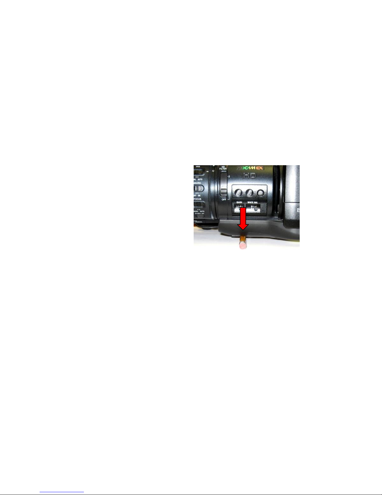
The simplest accurate way to find the camera’s center of mass is to lay a pencil/pen on a table
and try to balance the camera on it front-to-back. The spot on the camera where it comes closest to
balancing on the pencil is the center of mass. Place the camera’s center of mass at the center of the
mounting slot and secure the camera with mounting screws (2 if possible). When horizontally balanced,
the platform should stay level.
With smaller cameras (under 10lbs), you may not need to adjust the vertical balance. For larger
cameras, you may want to adjust it for optimal performance and to minimize the effort the servos have
to make to hold position. To get the vertical balance right, raise or lower the platform to get the
camera’s vertical center of mass located on the center of tilt rotation. To adjust, you will have to loosen
the lockdown screws (2) on each of the camera platform tubes. Once they are loose, turn the fluted
knob on the underside of the platform (between the tubes) to precisely raise or lower it. Rotate the
platform to various angles and adjust until it holds position at any angle. If it falls down, you need to
adjust the platform upward. If it drifts upward, you need to lower the platform. Note that if you can’t
get the vertical balance just right, the head will compensate when the servos are powered up. When
balance is achieved, tighten the lockdown screws on the platform tubes.
After all connections have been made and the camera is balanced, switch on power located on the
power brick.
After sync is established (the “sync” light on the jibstick should be illuminated), switch on motor power
(See below for location)
Center of Mass

Joystick deadband
2. Jibstick layout and functions
Communication connector (Green)- Connect this to the communication cable, and connect the other
end of the communication cable to the green connector on the CinemaPro Head. This cable runs
communication as well as power, so make sure that there is XLR power connected to the CinemaPro
Pan direction and Tilt direction- Reverses the response direction for each axis
Pan Speed
Pan direction
Communication Connector
Tilt direction
Tilt Speed
Smoothing
Pan/Tilt
Control joystick

Joystick for pan and tilt operation- Move the joystick in the direction you wish the head to move. The
response direction can be changed with the response direction switches.
Smoothing- Adjusts the amount of smoothing for both the pan and tilt axes. The higher the smoothing
is set the more “delay” there will be in response to the joystick.
Pan speed and Tilt Speed- Adjusts the maximum speed for the pan motor and tilt motor.
Deadband- Adjusts the amount the joystick must be moved before pan and tilt will respond.
3. Troubleshooting
No Response from head
1) Make sure that the motor power switch is turned on, and the light above it is green.
2) Check to make sure that there aren’t any soft limits set too close together. Disable all soft limits, and
then try again.
3) Power down the system, unplug the XLR connector, wait for a few seconds, re-plug everything back
in, power it back up, then try again.
Pan and Tilt moves too slowly or PanBar range is limited
1) Check both speed settings. If the speed is dialed too slowly it will appear to have no response at all.
Head is “jerky” or too responsive
1) Turn down motor speed.
5) If you have been using the advanced controller, check to make sure that the servo tuning in the
“tuning” menu is set to the factory setting. Selecting “reset all” will return this to the factory preset.
Note: When the jibstick is plugged into the head, it will default to the servo tuning of the last
advanced controller that used with the head.
4. Options and Specs
Additional Software- The Cinema Pro head can operate as a slave to Kuper Node motion control
software, and is also is capable of providing motion data for virtual set operation.

Data capture software is available, for data sharing. This will allow you to export the data from the
Cinema Pro to a personal computer.
Additional Head options-
The Cinema Pro head can be fitted with either a 100mm half ball, or Mitchell mount. A Mitchell ring
adapter is available for old style Mitchell mount.
An adapter is also available to adapt Mitchell mount to Jimmy Jib style mount.
Wireless control is available, and can controlled from up to ¼ mile. Up to 1 mile line of sight.
Additional controller cables are available in 50’ or 100’ increments. A male to female LEMO coupler is
available to join the cables.
Cinema Pro XLR power cables are available in 30’ or 75’ increments.
2” head extension blocks are available, and will increase the underslung clearance range from 16.5”-
18.5” to 18.5”-20.5”. A maximum of two can be installed. This will also increase clearance if using a
larger lens.
¼” or 1/8” nodal line offsets can be installed on the Cinema Pro’s camera mounting plate to line of the
center of the lens when necessary.
Dedicated video sliprings can be fitted on the Cinema Pro head to allow high quality SD video to pass
through the head. There is a 2db signal loss through this dedicated slip ring, so HD SDI is not supported
unless a line driver is introduced. This option will only support HD for monitoring purposes –the signal
will not be of broadcast quality.

HD hardwiring is available for a broadcast-quality HD video signal. (This cable will bypass the slipring,
and limit pan and tilt movements to 720°)
Specs-
Head construction: Primarily Aluminum, with carbon fiber platform rails and some stainless steel, steel,
brass, bronze components
Height: 19.5”
Width: 12”
Depth: 6”
Weight: 21 lbs.
Maximum speed: 210 deg/sec (max up to 512 deg/sec with custom high speed motors)
Underslung Camera Clearance for Standard Head = 15.5” – 17.5” (camera platform adjusts 2” up/down)
Underslung Camera Clearance w/ Head Extensions: w/ 1 extension = 17.5” – 19.5”;
w/ 2 Extensions = 19.5” – 21.5”
Mechanical travel: unlimited unless hardwired.
Camera Plate dimensions-
From Center mounting hole- tilt arm: 5” (with standard nodal line plate installed. This may be offset by
¼” or 1/8” with offset nodal line plates installed)

Camera plate has 2” of vertical adjustment for camera balancing.
Connectors-
Cinema Pro Base connectors
Head power- 4pin XLR
Kuper Node- 6pin LEMO (red)
Controller- 7pin LEMO (green)
Video out- BNC
Tilt arm connector, front
Lens control- 16pin LEMO (orange)
Tilt arm connectors, back
Video in- BNC
Bloop/sync (optional)- 6pin Fischer
Camera control (optional)- 12pin LEMO (white)
Camera Power- 2pin LEMO (red)

Advanced Controller connectors (not pictured)
CTRL - 7Pin LEMO –Head control cable (green)
SERIAL - 8pin LEMO –TOC or Preston Lens Drive Hand Units (gray)
ANALOG - 5pin LEMO –Pan Bars zoom & focus controls (white)
WHEELS - 6pin LEMO –Handwheels or Pan Bars Control Input (blue)
BLOOP - 6pin Fischer
VIDEO SYNC –BNC connector
Appendix
Power Supply Connectors
1) Power Connector –XLR4F
Pin Function Wire Color
1 Camera Neg. Black
2 Cinema Pro Neg. White
3 Cinema Pro Pos. Red
4 Camera Pos. Green
2) Camera Power Connector
Pin Function Destination
1 Camera Neg. Loop to Power Connector
2N.C.
3N.C.
4 Camera Pos. Loop to Power Connector
*** WARNING: DO NOT POWER THE CINEMAPRO WITH ANYTHING OTHER THAN THE
INCLUDED FACTORY POWER SUPPLY OR YOUR WARRANTY MAY BE VOIDED. THE
UNIT MAY BE SEVERELY DAMAGED AND CAUSE DAMAGE TO YOUR CAMERA IF YOU
USE A NON-APPROVED POWER SUPPLY. IF YOU MUST POWER IT USING A BATTERY
SYSTEM, MAKE SURE THE SETUP IS APPROVED BY VARIZOOM AND EXECUTED BY A
QUALIFIED TECHNICIAN.

Cinema Pro Head - Base Connectors
1) Control Connector (green) –LEMO EGG1B307CLL
Pin Function Wire Color (Cable)
1 Common Brown
2 RS-422 TXD Red
3 RS-422 TXD! Orange
4 RS-422 RXD Yellow
5 RS-422 RXD! Green
6 24 VDC + Blue Power to Remote or Jibstick
7 24 VDC - Violet Power to Remote or Jibstick
2) Kuper Node Connector (red) –LEMO EGG1B306CLL
Pin Function DB9
1 Common 1
2N.C.
3RS-422 RXD (Kuper) 8
4RS-422 RXD! (Kuper) 9
5RS-422 TXD (Kuper) 5
6RS-422 TXD! (Kuper) 6
3) * Optional - Camera Control Input Connector –EGG2B310CLL
Pin Function
1Common
212 VDC out
3Run Switch
4Remote Enl
5Remote Clock
6Remote Direction
7Clock out
8Sync out
9N.C.
10 N.C.
4) * Optional - Peripheral Connector –EGG1B308CLL
Pin Function
1 Common

2 #1 RS-232 RXD
3 #1 RS-232 TXD
4 +5 VDC
5 24 VDC -
6 #2 RS-232 RXD
7 #2 RS-232 TXD
8 24 VDC +
Cinema Pro Head –Tilt Arm Connectors
1) Camera Power (red) –LEMO EGG2B302CLL
Pin Function
1 Camera Power +
2 Camera Power -
2) Sync & Bloop –Fischer D103A056-130
Pin Function
1 Common –Iso
2 +5 VDC –Iso
3 Sync In
5 Bloop Out #1
6 Bloop Out #2
2) Camera Control (white) –LEMO EGG2B312CLL
Pin Function
1 Common
2 Enable
3 Run –push/pull 12 volts
4 Camera run relay Pin1
5 Run pulse –5 VDC
6 Clock out –5 VDC
7 Clock out –12 VDC
8 Clock return

9 RS-232 TXD
10 RS-232 RXD
11 Camera run relay pin2
12
3) Lens Control (orange) –Tilt Board Version #2 LEMO EGG2B316CLL (Final Version)
Pin Function Lens Connection
1 RS-232 RXD Fuji Digital
2 RS-232 TXD Fuji Digital
3 +5 VDC –Iso Fuji Digital
4 Common –Iso Fuji Digital
5 RS-422 RXD Canon Digital
6 RS-422 RXD! Canon Digital
7 RS-422 TXD Canon Digital
8 RS-422 TXD! Canon Digital
9 Common
10 +5 VDC
11 Analog #1 Focus
12 Analog #2 Zoom
13 RC Servo #1 Focus
14 RC Servo #2 Zoom
15 24 VDC +
16 24 VDC –

Lens Connection Table
Lens Control, 16 pin LEMO FGG2B316CLAD
Fujinon Digital
Fujinon Analog
Fujinon Telecon
Canon Digital
Canon Analog
HR10A-10P-10P
HR10A-10P-12P
HR10A-10J-12P
HR25-9P-20P
HR25-9P-20P
1
Camera Run Relay
3
2
Camera Run Relay
2
3
Iso Vcc
4
4
IsoCom & IsoCom3
5
19 & 20 - Green
5
RS-422 RXD
17 - Orange
6
RS-422 RXD!
18 - Yellow
7
RS-422 TXD
15 - Brown
8
RS-422 TXD!
16 - Red
9
Common
2
3
20
10
Vcc (5 volts)
11
Analog #1 out
7 (If zoom)
9 (Zoom)
2
12
Analog #2 out
7 (If focus)
8 (focus)
3
13
RC Servo Out 1
14
RC Servo Out 2
15
Head power + out
16
Head power –out
Tie pins 1 & 2 to 7
for position control
Advanced Controller Connectors (console connectors)
1) Auxiliary power input
1Center 18 to 36 volts input
2Common

2) “CTRL” - Cinema Pro Control (green) –LEMO EGG1B307CLL
Pin Function Wire Color (Cable)
1 Common Brown
2 RS-422 RXD Red
3 RS-422 RXD! Orange
4 RS-422 TXD Yellow
5 RS-422 TXD! Green
6 24 VDC + Blue Power from Cinema Pro
7 24 VDC - Violet Power from Cinema Pro
2) “SERIAL” - Peripheral Connector (gray) –EGG1B308CLL
Pin Function
1 Common
2 #1 RS-232 RXD
3 #1 RS-232 TXD
4 +5 VDC
5 24 VDC -
6 #2 RS-232 RXD
7 #2 RS-232 TXD
8 24 VDC +
3) “ANALOG” - Panbars Option Zoom and Focus Control Input (white) –EGG1B305CLL
1Common
2Motor disable
3Zoom analog signal
4Focus analog signal
5+5 VDC
4) “WHEELS” - Wheels and Panbars Option Control Input (blue) –EGG1B306CLL
1Common
2+5 VDC
3Pan encoder signal “A”
4Pan encoder signal “B”
5Tilt encoder signal “A”
6Tilt encoder signal “B”

5) “BLOOP” - Sync & Bloop –Fischer D103A056-130
1 Common –Isolated
2 +5 VDC –Isolated
3 Sync In
5 Bloop out #1
7Bloop out #2
6) “VIDEO SYNC” - BNC
1BNC signal
2Isolated common
Jibstick Connectors
1) Cinema Pro Control (Green) –LEMO EGG1B307CLL
Pin Function Wire Color (Cable)
1 Common Brown
2 RS-422 RXD Red
3 RS-422 RXD! Orange
4 RS-422 TXD Yellow
5 RS-422 TXD! Green
6 24 VDC + Blue Power from Cinema Pro
7 24 VDC - Violet Power from Cinema Pro
2) Focus Input –Fischer D103A054-130
1Common
2+5 VDC
3Focus analog signal
4Zoom analog signal (unused)
5Common
Table of contents
Other VARIZOOM Camcorder manuals