VARIZOOM Cinema Pro User manual

- 0 -
Cinema Pro
Operations Manual

- 1 -
BEFORE YOU START, READ THESE WARNINGS
1) NEVER PLUG POWER DEVICES OTHER THAN THOSE SUPPLIED BY
VARIZOOM INTO THE SYSTEM. ONLY USE VARIZOOM POWER
SOURCES AND CABLES. USING DIFFERENT POWER COMPONENTS
CAN LEAD TO SEVERE DAMAGE TO THE HEAD AND EVEN THE
CAMERA. THIS TYPE OF DAMAGE IS NOT COVERED UNDER
WARRANTY.
2) DO NOT MODIFY THE SUPPLIED CABLES OR ATTEMPT TO
DISASSEMBLE THE HEAD.
3) LENS CONTROL CABLES MUST ONLY BE PLUGGED INTO THE
SPECIFIED INPUT JAC ON THE LENS ITSELF – NEVER PLUG A
12-PIN CONNECTOR ON A VARIZOOM LENS CONTROL CABLE
INTO THE 12PIN JAC ON THE CAMERA BODY. WHEN IN DOUBT,
CONSULT VARIZOOM OR YOUR LENS MANUAL.
4) THE ADVANCED CONTROLLER DOES NOT REQUIRE SEPARATE
POWER, IT RECEIVES POWER THROUGH THE GREEN-CODED
CONTROL CABLE THAT CONNECTS TO THE HEAD. THE “AUX”
POWER JAC ON THE ADVANCED CONTROLLER IS ONLY
UTILIZED IN WIRELESS CONFIGURATIONS AND SHOULD ONLY BE
CONNECTED TO A VARIZOOM POWER SUPPLY.
5) DO NOT OPERATE THE HEAD WITH AN UNBALANCED LOAD
(i.e., with the camera’s weight extremely off-center either
horizontally or vertically).
6) DO NOT GET THE SYSTEM WET – IT IS NOT WATERPROOF.
7) MA E SURE YOUR LENS CLEARS THE BASE OF THE HEAD WHEN
TILTING. IF THE LENS DOES NOT CLEAR THE BASE, SET SOFT
LIMITS (SECTION 7) TO PREVENT THE LENS FROM STRI ING THE
BASE OF THE HEAD WHEN TILTING.

- 2 -
General Description
The Cinema Pro is a mid-size, two axis motion control head. It has a
wide variety of operating modes: manual operation from joystick, optional
hand wheels or pan bars control, motion control style record and playback, “go
to mark” preset framing, intervalometer operation and can operate as a slave
to uper Node motion control. It also is capable of providing motion data for
virtual set operation.
The Cinema Pro Advanced Controller gives the user all input and
programming capabilities and has a joystick for pan & tilt control. The
Advanced Controller also works in concert with two optional control input
devices: Pan Bars for broadcast-style operation or Hand Wheels for cinema-
style operation.
The Jibstick remote is a simpler, less expensive controller designed for
one-man jib operation. The jibstick only offers joystick pan & tilt with
smoothing and speed control.
The Cinema Pro’s lens interface controls zoom, focus and iris. It provides
four varieties of control signals: RS-232 for Fujinon digital lenses or Varizoom
(TOC) motor drives, RS-422 for Canon digital lenses or Preston motor drives,
position or speed based analog, pulse width type RC servos, and LANC.
The following is an in-depth description of Cinema Pro operation and a
complete description of each of its features.
Cinema Pro Advanced Controller
Front Panel buttons: – The top row of buttons default to act
like a normal record - playback system; record, rewind, stop
and play. The top left button, ‘Q’, is used as a ‘Shift’ key.
The bottom row includes:
The “Menu” button = ‘*’
The “Accept” button = ‘<-‘
The “Cancel” button = ‘x’
The main page may always be enabled by pressing the “Cancel” button one to three
times, depending on which sub-menu you start out from.

- 3 -
The upper right portion of the LCD screen shows motor status and current positions for
pan, tilt, zoom and focus. A check in the box to the left of the axis name indicates that
that motor is enabled to run. If soft limits are enabled for the axis, the box is filled and
appears white with a blue check mark. The numbers to the right of the axis names are the
motor positions; pan and tilt are shown in degrees, and zoom and focus are shown as an
unscaled number from 0 to 1000.
1. Navigating the menu screens
Use the knob above the joystick to navigate through the menu screen. This knob (called
the setup knob) will also be used to change the value of selected parameters.
Use the “enter” button to select an item.
The “menu” button is used to enter setup menu.
When pressed while already in the setup menu, the “menu” button will enter a second
setup menu.

- 4 -
The “cancel” button is used to cancel the last item changed, or to back out of a sub menu.
Pressing “cancel” twice will always return to the main screen.
The “Q” button is basically a shift key, and is used to change the function of other
buttons.
The “Record” “rev” “stop” and “play” are used for the motion control features. This will
be addressed later on.
The main menu screen will show pan, tilt, zoom, and focus positions. It will also display
which take is enabled, which go to mark is enabled, as well as a few basic functionality
adjustments.
When changing the value of a parameter, the setup knob will increase or decrease the
value in increments of 1. Hold the “Q” button while moving the setup knob, and the
values will move in increments of 10. Hold the “menu” button while moving the setup
knob, and values will move in increments of 100. Hold both the “Q” and “menu” buttons
while moving the setup knob, and the values will change in increments of 1,000.
Display Contrast can be adjusted from the second setup menu.
While in the main screen, press the “menu” button twice.
Select the “contrast” option.
Contrast can be adjusted from 0-100
2. Basic Setup
Secure Cinema Pro head to crane, tripod, or solid mounting beam
Plug the FACTORY POWER SUPPLY into AC mains
Connect XLR cable between the Cinema Pro head and FACTORY POWER SUPPLY
Connect in Green LEMO connector between the Cinema Pro head and the plug marked
“CTRL” on the controller
Connect camera control (if applicable) between the camera and the 12-pin LEMO
connector on the back of the tilt arm on Cinema Pro head .

- 5 -
Connect camera power (if applicable) between the 2-pin LEMO connector also located
on the back of the tilt arm
Connect the bloop/sync (if applicable) between the camera and the 6-pin Fischer
connector also located on the back of the tilt arm
If using the TOC system
Connect the TOC 3A (3 axis lens drive box) between the orange 16-PIN lens control
connector located on the front of the tilt arm of the Cinema Pro head, and the grey
“control” port located on the TOC 3A
Connect the Lens drive motors to the appropriate connection according to their function
(zoom, focus, iris)
If using a Preston MDR2*
Connect the MDR2 box between the 16-pin LEMO connector located on the front of the
tilt arm of the Cinema Pro head, and the appropriate command connected on the MDR2
box (refer to the manufacturer’s instruction manual for proper connections)
Connect the Preston lens motors according to their manufacturer’s instruction manual
* make sure that the MDR2 is not connected to any power source
(including batteries) prior to connecting to the head. This can result in
damages to the control console. The MDR2 will get all necessary power
directly from the head.
Balance the Camera – Although the head will hold position very well, it operates best
when the camera is balanced on the mounting platform. With heavier cameras, it is
essential, as an out-of-balance load will cause the servos to constantly fight to hold
position. Make sure that the motor power is turned off before balancing. This will
allow you to move the tilt axis by hand. To balance the camera horizontally, you need
to place the camera’s front-to-back center of mass at the center of the mounting platform
slot. You can do this by trial and error, sliding the camera front-to-back on the mounting
platform until it stays level.
The simplest accurate way to find the
camera’s center of mass is to lay a pencil/pen on a
table and try to balance the camera on it front-to-
back. The spot on the camera where it comes
closest to balancing on the pencil is the center of
mass. Place the camera’s center of mass at the
center of the mounting slot and secure the camera
with mounting screws (2 if possible). When
horizontally balanced, the platform should stay
level.
Center of Mass

- 6 -
With smaller cameras (under 10lbs), you may not need to adjust the vertical balance. For
larger cameras, you may want to adjust it for optimal performance and to minimize the
effort the servos have to make to hold position. To get the vertical balance right, raise or
lower the platform to get the camera’s vertical center of mass located on the center of tilt
rotation. To adjust, you will have to loosen the lockdown screws (2) on each of the
camera platform tubes. Once they are loose, turn the fluted knob on the underside of the
platform (between the tubes) to precisely raise or lower it. Rotate the platform to various
angles and adjust until it holds position at any angle. If it falls down, you need to adjust
the platform upward. If it drifts upward, you need to lower the platform. Note that if you
can’t get the vertical balance just right, the head will compensate when the servos are
powered up. When balance is achieved, tighten the lockdown screws on the platform
tubes.
After all connections have been made and the camera is balanced, the head will be ready
for initial calibration.
Switch on power located on the power brick.
Switch on the Cinema Pro head power located on the controller (the power switch on the
left)
After sync is established (a spinning diamond will appear in the lower left corner of the
remote. After the diamond stops spinning, sync is established between the Cinema Pro
head and the controller), switch on motor power (the power switch on the right)
Calibrate ”Home sense”. This will calibrate the sensors so that the position markers
will be accurate. This needs to be done any time one of the axes is moved while power is
off, or if the Cinema Pro head has been operated in oneway communication mode.
Select “GoTo” from the main menu screen. Then select “Home” from the sub menu.
The screen will then read “ready to calibrate?”. Press “enter” again, and the head will
then calibrate home sense.
Set inputs- You will now need to set the Cinema Pro head to respond to the correct
controller inputs.
Press the “menu” button to bring up the setup menu.
Select the “inputs” option. This will bring up a controller inputs grid.

- 7 -
Here is where you can assign how Pan, Tilt, Zoom, and Focus will be controlled.
Move the cursor box to where you’d like to control each axis.
Note: Make sure you have the correct controller selected. I.E. if you are using wheels,
make sure “wheels” is selected rather than “panbar”. This will greatly effect the
performance of the Head.
Overslung/Underslung- Make sure this selected for the proper configuration. If this
needs to be changed, simply move the cursor box over the selection, and press “enter”.
This will change the Pan response.
Lens-This only needs to be changed if you are using camera lens controls other than
the VariZoom TOC system. In other words, if you’re connecting directly to a Canon or
Fujinon lens servo, or even a Preston system, you’ll need to go into this menu to set
things up properly.
Press the “menu” button to enter the main setup menu.
Select the “Lens” option.
When the “Current Lens” box is selected, pressing “enter” will change the selection.
Preston
If you are using a Preston MDR2, press the “enter” button until the box reads “Preston.”
Canon or Fujinon Analog Servos
If you are using a Canon or Fujinon lens with an analog zoom servo, press the “enter”
button until “default” appears.
Connect the Lens Control Cable
To set up the lens control, you need to first connect the lens cable to the servo jack(s) on
the lens itself (NEVER connect to the jack on the camera body where the lens plugs in, or
damage may occur). You will plug into the same jack(s) where you would plug in any
external lens control, so consult your owner’s manual if necessary.
Adjust the Voltages
You must then adjust the voltages in the lens menu so the lens servo responds properly –
you may notice the lens zooming on its own when you first connect the cable, but this is
normal. Start by adjusting the middle number until the lens servo stops zooming. If the
lens is all the way at one end of the range, you may need to manually zoom the lens in or
out to reset the position in order to see if the servo is still moving. (Some people also flip
the lens servo switch to manual and just listen to hear the servomotor stop running)

- 8 -
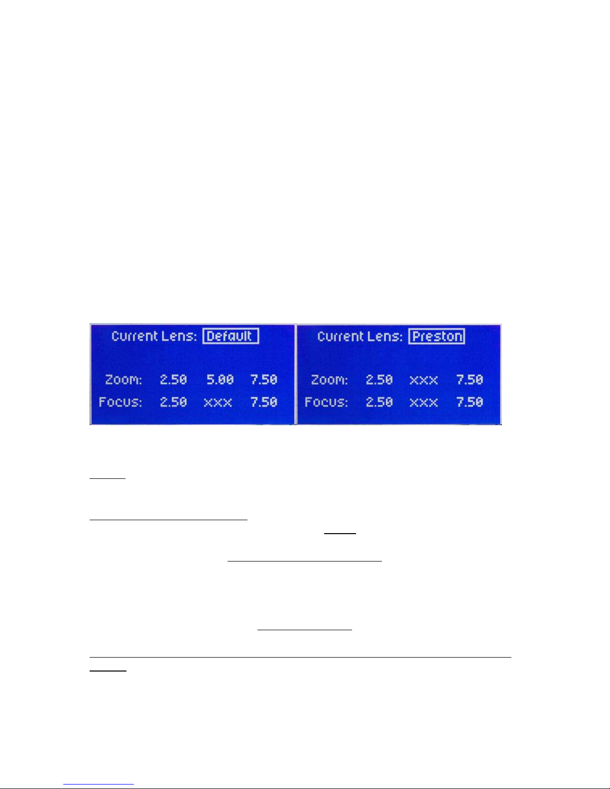
Once you’ve set the middle number to the proper rest voltage, you need to make sure the
voltages on the left and right are equally far from the middle “rest” voltage. In other
words, if your rest voltage is 4.00, the left voltage could be 1.50 and the right 6.50.
If the difference is unequal, you’ll notice the lens zooms faster in one direction than the
other. The greater the difference, the faster the lens will zoom in that direction. The left
number should always be lower than the middle number and the right number should
always be higher than the middle number.
Canon or Fujinon Digital Servos
If you are using a Canon or Fujinon lens with digital servos, press “enter” until the lens
manufacturer’s name appears. Digital servos should automatically work with no setup.
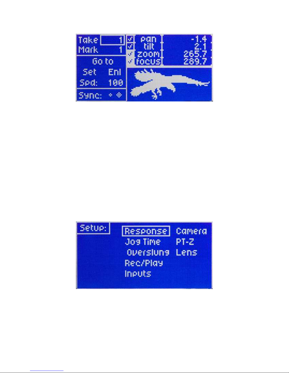
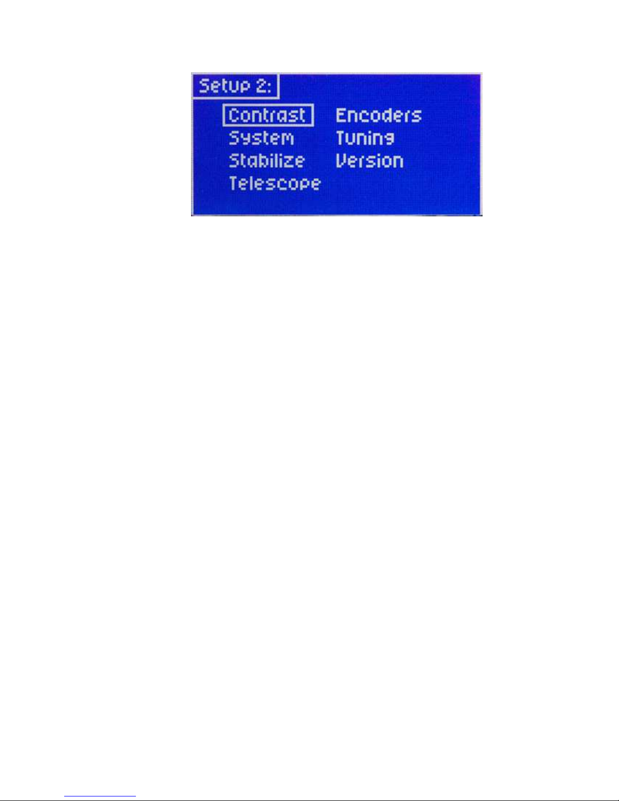
Head Setup- Press the “menu” button twice to enter the secondary setup menu.
Select the “head setup” option.
If you are using the Head wired, change the “communication” box to read “two-way”,
and change the “head type” to read “wired”
If you are using the Head wireless, change the “communication” box to read “one-way”,
and change the “head type” to read “wireless”
Warning: In the “Head setup” menu, there is also a set of head speed options: “S-
Standard,” “HS - High Speed” and “HSX – Ultra Speed” – DO NOT CHANGE THIS
SETTING FROM “S – Standard” – THE CP SHOULD ALWAYS BE SET TO “S –
Standard”, unless you special ordered a high-speed custom head, in which case the
factory would have already preset the correct selection in this menu.
3. Basic operation and adjustments
WARNING: If your lens has an optical image stabilizer (OIS), we recommend that
you disable the OIS. The motion of the head may cause the OIS to exhibit some strange
behavior. In some cases, the OIS may create the illusion that the head is drifting at 90
degrees to the axis of motion (e.g., at the end of a pan move, the image may “tilt” slightly
up or down). Turn off the OIS to prevent optical problems.
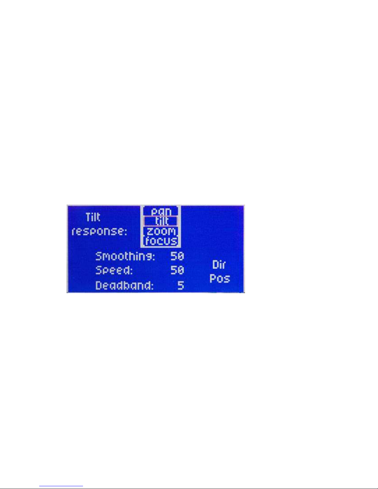
The Head can control Pan, Tilt, Zoom, Focus, and record start/stop (when available from
the camera) from the advanced controller, and has programmable parameters for each
axis. Iris can also be controlled from an optional FIZ controller.
Pan, tilt, and zoom can be controlled with the joystick by moving the joystick forward,
backward, left, right, or twist for zoom.
Pan and Tilt can also be controlled by using the optional encoded handwheels or with the
optional panbar controller pan and tilt to be controlled as if using a fluid head. This can
also be fitted with optional Pro style zoom and focus controls.

- 9 -
Focus is controlled with the knob to the left.
Record start/stop is done by holding the “Q” button and pressing the “enter:” button. A
“C” (for camera) will appear next to the “Go To” option when camera record has started.
Speed adjustment
Basic speed adjustment for pan and tilt can be made in the main menu screen. Move the
cursor box to “spd” using the setup knob, and press “enter”. The setup knob will then
change the speed for both pan and tilt (the number shown in the box is a percentage of the
advanced speed setting). Pressing the “enter” button again will allow you to change the
advanced speed setting. In this menu the setup knob will adjust tilt speed, and the focus
knob will adjust pan speed. The number shown in the box is a percentage of full speed
capability. Press enter again to keep your selection, and return to the main screen.
4. Motion response
From the main screen press the “menu” button, Select the “response” menu.
Here you can adjust parameters for Pan, Tilt, zoom, and focus. Select the axis that
you’d like to adjust.
Smoothing will adjust how “quick” the axis will respond. Smoothing can be adjusted
from 1-100. 1 being instant response, and 100 being the maximum delay in response.
Smoothing will also affect the how quick the axis will slow down while making the
move.
Speed will adjust the advanced speed setting. The numbers in the box are the same
numbers that appear in the advanced speed setting accessible from the main screen.
Deadband only affects the joystick. It will adjust the amount the joystick must be moved
before the axis responds. Deadband can be adjusted from 1-100. 1 being minimum
amount of movement before response, and 100 being maximum amount of movement
before response.
Direction- In will change the direction in which the signal is sent to the head. It is what
you will need to change to reverse axis responds. I.E. if tilt is set + turning the encoded

- 10 -
wheel clockwise will tilt the camera up, and pressing the joystick forward will tilt the
camera down. If it is changed to – turning the encoded wheel clockwise will tilt the
camera down, and pressing the joystick forward will tilt the camera up.
Direction- Out will change the direction in which the head sends the signal back to the
controller. This will change the axis positions on the main screen display as they relate to
zero. I.E. a pan maneuver from left to right will have decrease the angle if the output
direction is marked as+. Switching the output direction to – will result in the angle
number increasing when a pan maneuver is made from left to right.
5. Motor Enable/Disable
To enable or disable control of pan, tilt, zoom, or focus, or to place pan or tilt in neutral,
while in the main screen select the “ENL” option.
The cursor box then appears in the top right corner, and lets you select one of the four
axes. Move the cursor over which axis you wish to control.
Pressing “enter” will disable, or enable that axis from the controller. When disabled,
power will remain to this axis, so it will hold its position. It will just be disabled from
control.
While holding “Menu”, press the “enter” button. This will place the selected axis (this
only works for pan or tilt) in neutral. That axis not only will be disabled from the
controller, and will no longer be powered allowing you to move the axis by hand.
From this menu, you can also set each axis for live playback, or manual control (this only
applies when playing back a move which will be addressed in a later chapter)

- 11 -
Note: A check mark next to the axis indicated that the axis is enabled.
An “x” next to the axis indicates the axis is disabled.
An “o” next to the axis indicates an axis that is in neutral.
A blue check mark with a white background indicates an axis with a soft limit set
If the name of the axis appears blue with a white background, this indicates an axis that is
set for live control during playback of a move (this will be addressed in a later chapter)
6. Setting Zero
You can custom set the axis position indicator to read zero wherever is necessary.
Move each axis to your desired zero point**.
From the main screen select the “set” option. Then a sup menu will appear to the right.
Select the “zero” option.
All axes will then reference their current position as zero.
**If using the TOC system, Preston MDR2, or any Canon of Fujinon lens with digital
servo control. Setting zero will only affect pan and tilt. Zoom, and focus will be
referenced to the actual motor position.
You can always return all axes to zero at any time.
From the main screen, select “Go To”
From the sub menu, select “Zero”
All axis will then return to the zero position
7. Soft Limits
Soft limits will allow you to limit the range of the pan, tilt, zoom, or focus axes. This is
very useful if you have any hard wired cables that will restrict pan or tilt movement, or
any lenses that limit clearance. You can set two limits per axis.
From the main screen select the “set” option. A sub menu then will appear to the right.
Select the “soft limits” option.
Select the axis that you’d like to set soft limits.

- 12 -
When setting a limit, leave the soft limit as “disabled”
Move the selected axis to the desired limit.
Then select “set limit”
Now move the axis in the other direction to where you need the other limit set.
Select “set limit”
Now move the cursor box to “Disabled”, and press “enter” The box now shows
“enabled”, and your soft limits are set that that particular axis.
Note: If the system is setup to be in “one-way” mode, you can quickly enable or disable
pan and tilt soft limits from the main screen.
While in the main screen Hold “Q” and press “record”. This will enable or disable pan
and tilt soft limits.
Reset Zero will set the current position of the selected axis to read as zero.
Set Default will automatically set the selected axis to + 90o and – 90o from its current
position. This is just for a quick limit set that doesn’t require the operator to have the
head in any direction.
Reference is the point from where the soft limits are set. You can change this to
“sensor” or “zero”. If reference is set to “zero” then the limits will be set based on how
far the axis is from the zero position. In this case, the soft limits will change position if
zero is reset. If “sensor” is selected, the limits will be set regardless of where their zero
position is. In this case, if you reset zero the soft limits will not change their position.
Note: If any axis is moved by hand while the Head is not powered, the sensor position
will have changed once it is powered up again. You must then re-calibrate “home sense”
(as addressed in the previous chapter) in order to restore the soft limits to their correct
positions.
8. Mark points
The controller can store 2,000 preset positions for any axis.
Setting Marks
To set a mark point, select “Mark” on the main screen.

- 13 -
The number in the box will indicate where your mark will be stored. As you scroll
through the numbers, the lower right will display the current positions recorded for each
mark.
Once you choose where you want to store the mark, press “enter”
Move the axes to the position that you wish them to set for this mark position.
Select the “set” option.
From the sub menu select “Mark”
This will then record all current axes positions to the mark displayed in the upper left.
Recalling Marks
To recall a mark position, select the “Mark” number you wish to recall from the main
screen. (The axis positions will be displayed in the lower right)
Select the “Go To” option
From the sub menu, select “Mark”
All axes will go to the position that is recorded for this mark.
Note: A quick way to scroll through marks. While holding the “Q” key, press “Play” and
the mark numbers will increase. Press “Stop” and the mark numbers will decrease. This
is much faster than scrolling with the setup knob.
Jog Time is the speed and time that the Head will take to move to and from a mark, or to
and from zero. This can be adjusted for linear ramping, and will be addressed in more
detail in a later chapter.

- 14 -
9. Recording moves
The Cinema Pro can record up 4,650 seconds of moves, and store them as up to 2,000
different takes. They will be played back in real time, or over an intervalometer (The
intervalometer will be addressed in a later chapter)
Recording a move- Select the take where you want to store the move. From the main
screen, move the cursor box to the number next to the “take” option..
From here, you can select the take where you want to store your move.
The bottom left will display how long the existing take is (if it is empty it will display
“0”), and how many seconds are available for recording in the system’s memory.
Press the “record” button. If a move is already stored it will read “overwrite take?”
Press enter to overwrite. It will then read “hit record to start”
Once you hit record, it will instantly begin recording the moves for all applicable axes
(pan, tilt, zoom, focus, and iris)
When you are done, press the “stop” button
Note: You can record a “go to mark” maneuver.
Before you begin recording, make sure that the desired mark is already displayed in the
upper left.
Begin recording.
Any time during the recording hold the “Q” button and press “play”. The Head will then
automatically move from the current position to the mark point displayed in the upper
left. This can be done as many times as necessary during the recording.
Playing back a move- Select the take that you wish to play back
Press the “play” button. All recorded axes will then move to the starting point of the
selected take.
After the all axes have returned to the start point, press “play” again, and the Head will
play back the recorded move.
Note: During playback of a move, the joystick, panbars, or handwheels, will be disabled
until the axes are done playing back the move.

- 15 -
Manual control on axes during playback- It is possible to isolate a specific axis or axes
to be disabled from playing back while the other axes play back the move.
From the main screen select the “enl” option.
Then select which axis you’d like to disable from playback
On the lower left, next to “playback” it will display either “active” or “live”
When “active” is displayed, the axis will be played back during a move.
When “Live” is selected, the axis will be disabled from playback, but you will be able to
control that axis with the controller while the other axes playback the move.
Note: When selecting a take for playback, or recording, hold the “stop” button while
turning the setup knob. This will skip to the next take that has a move recorded. I.E. if
you have a move recorded on take 2, and a move recorded on take 12, and moves 3-11
are blank, this will scroll the numbers directly from take 2 to take 12.
Delete a take- Select the take that you want to erase.
While holding “stop” press “record” This will then erase the move that is stored on the
selected take.
10. The Intervalometer
The intervalometer allows recorded moves to be played back over a specified time and,
when camera sync is enables, will control the number of frames that will be taken during
that time. To activate the intervalometer, select the “record/play” option from the setup
screen.
Select “playback time”.

- 16 -
The intervalometer has three modes. “Playback Time Mode”, “Playback Ratio Mode”,
and “Stop Motion Mode”.
-Playback Time Mode
This mode allows you to select a specific time that the head will take to play out a
recorded move.
Adjust the time you wish for the move to be played back. (the playback time selected
must be greater than the move time)
Move the cursor box over “disabled”, and select it. It will then change to “enabled”, and
all moves will be played back according to these settings.
If you have “camera sync” enabled, you can select the number of frames that will be
taken during the selected time. The “Start Frame” setting will allow you to start in the
middle of a take, if you ever need to replay a move, but don’t need to replay if from the
beginning. Setting the “Start Frame” to anything other than one will start the move from
the position that corresponds to the selected frame.
Note: all of these settings will be applied to all recorded moves. If a move has a greater
recorded time than what the intervalometer is set to, the move will not play until the
intervalometer is either disabled, changed to a different mode, or the playback time is
adjusted to be greater than that of the selected take.
-PB Ratio Mode
This mode allows you to change the playback of a move according to the frame rate. The
“Rec FPS” will adjust the invervalometer to record the move at this specified frame rate.
The “Play FPS” will adjust how the move is played back. For example; if a move is
recorded at 30Fps, and the Playback is set to 15Fps, the move will play back at half
speed.
This mode will also allow you to play a move faster than it was recorded. If the Play Fps
is set higher than the Rec Fps, the move will be faster than is was recorded.
-Stop Motion Mode
This mode allows you to play back a move by triggering it frame by frame. This works
much like a “frame mode” on a camera. When this mode is selected, the move will be
scaled down according to the “playback frames”. After you set the number of playback
frames, return to the main menu, and select your desired move, and press the “play”
button. The head will then move to the start position. From now on, each time you press
the “play” button, the head will move to the position that corresponds to the next frame
until the total number of frames is reached.
If “camera sync” is enabled, the head will trigger the shutter each time the “play” button
is pressed.
***You can also adjust the delay between when the shutter is triggered and when the
head moves to the next frame. If you change the intervalometer back to “Playback Time

- 17 -
Mode”, the time specified here will be the shutter delay time when operated in “Stop
Motion Mode”. After you select the desired shutter delay time, change the
intervalometer back to “Stop Motion Mode”. The shutter delay will now be set. (set it to
“0” if no shutter delay is desired)
11. Bloop Delay/Camera Sync
Bloop delay will allow you to choose the number of seconds before it will take for the
head to begin playing back a move after the “play” button is pressed. This can be used in
conjunction with a bloop light or trigger.
Sync is where you can synchronize move playback with your camera’s shutter pulse.
When both “Sync” and the intervalometer are enabled, the Cinemapro will trigger the
camera shutter according to the number of playback frames during playback.
“sync” will also allow you to feed the Cinemapro a frame pulse from film cameras.
When “sync” is turned on, the head will synchronize the move according to the frame
pulse. If there is any lag in this, you can use the “cam phase” to adjust the difference.
Virtual sync is used to generate a virtual “frame pulse” when using a digital format
camera or any camera that doesn’t give a frame pulse. This will sync the move to
whatever FPS you specify in this menu.
12. Jog Time
Jog time is the time the Head will take to or from a mark or zero.
Select “Jog Time” from the setup menu
Under the “jog time” option, you can set the number of seconds the Head will take to go
from mark to mark, from zero to mark, or from mark to zero.
Under “jog motion” you can choose either “s-curve” or “linear”. This is how the speed
will vary throughout the motion.
“s-curve” will start slow, speed up, then slow down before all axes reach their
destination.
“Linear” will start slow, and then increase speed. Maximum speed will be reached at no
more than 50% of the move.
“linear ramp” will adjust the percentage of the move the Head will take to reach full
speed in while “linear” is selected.

- 18 -
13. PT-Z
PT-Z is the menu where you can change the Pan/Tilt sensitivity according to the position
of the zoom axis.
PT-Z can be adjusted between 0-100. The greater the number the slower the pan and tilt
axes will respond according to the position of the zoom axis. When 0 is selected, zoom
will not affect the pan and tilt axes.
Note: This is only accurate when using the Varizoom TOC system, Preston MDR2,
Canon lens with digital servos, or Fujinon lens with digital servos. If you are using a
Canon or Fujinon lens with Analog Servos, the zoom positions will not be accurate, and
with feature will not function properly.
14. Servo Tuning
Servo tuning is changed from the “tuning” option in the second setup menu.

- 19 -
These settings are factory preset, and should never be changed. If they
have been changed, they must be changed back to the following, or the
Pan and Tilt motors can be damaged.
KP: 80 KI:15
KD:250 IL: 25
After the setting is made, move the cursor box to the “ok” option, and press “enter”. The
settings will not be saved until this is done.
Settings should be the same for both pan and tilt axes.
15. System resets
The “reset all” option is found in the second setup menu screen.
When selected this will reset all parameters only. All stored marks, and takes will not be
effected.
To reset all motor parameters only, turn the console power off
Hold the “cancel” and “stop” button simultaneously. While holding both buttons turn
console power on.
The screen will then read “Accept = reset all motors”
Press the “enter” button, and all motor parameters will be reset.
To erase all takes turn console power off.
Hold the “cancel” and “record” buttons simultaneously. While holding both buttons turn
console power on.
The screen will then read “Accept = erase all takes”
Press the “enter” button, and all takes will be erased.
To erase all marks turn console power off.
Hold the “cancel” and “play” buttons simultaneously. While holding both buttons turn
console power on.
The screen will then read “Accept = erase all marks”
Press the “enter” button, and all marks will be erased
Note: resetting all motor parameters is recommended after updating system software. It
is also recommended if the systems memory ends up corrupted.
16. Troubleshooting
Table of contents
Other VARIZOOM Camcorder manuals