Veikong VFD500 Series User manual

VFD500 Double screen Display LED
Keyboard User Manual

1
1. Product Introduction
The LED keyboard consists of two rows of digital tubes, nine indicator lights, six button
and one number knob; the first row is used for monitoring parameters and auxiliary
display, and the second row is used for parameter setting, operatiol control and
monitoring.
The appearance of the LED keyboard is shown in Figure 1-1:
Figure 1-1 Dual Line Display LED Keyboard

2
The specific buttons and indicator functions are shown in Table 1-1:
Table 1-1 buttons and indicator functions description
Number
Picture
Name
Function
1
ESC: Exit Button
-Return to the previous
menu.
-Select list.
2
ENTER:
Confirmation
-Enter the next menu.
-The parameters take effect
and are stored in EEPROM.
3
MK:
Multi-function
Button
-The default is positive
transmission electric. Its
function can be changed by
parameter 21.02.
4
SHIFT:Right
Shift
-Cursor shift.
-The monitoring status
displays the next monitoring
data. (Only the second line of
digital tubes can be
operated)

3
5
RUN:Run Button
-When the command source
is the keyboard, it is used to
run the inverter.
6
STOP:Stop
Button or Reset
-In the running state, press
this button to stop running
(restricted by parameter
21.03).
-When a fault occurs, press
this button to reset.
7
UP/DOWN/ENTER:
Number Knob
-Rotate clockwise or
counterclockwise, the
number indicated by the
cursor increases or
decreases by 1.
-Switch to the next or
previous function code.
-Pressing is equivalent to the
confirm button.
8
Hz: Frequency
-The unit of value is Hertz.
9
A: Current
--The unit of value is Ampere.

4
10
V: Voltage
-The unit of value is Volt.
11
RUN: Running
lights
-Turn off to indicate shutdown
status.
-Steady light means running.
12
REV: Direction
indicator
-Steady light means reverse.
13
ALM:
Fault indicator
-When it's on, it means the
inverter is faulty
Note: Communication distance <30m
2. Hierarchical display and menu mode
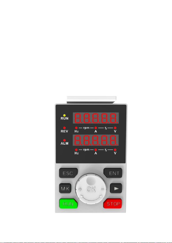
The display of the VFD500 dual-line display LED keyboard is divided into two lines, the
first line is used for monitoring and auxiliary display, and the second line is used for
switching monitoring, menu mode, function code selection, parameter editing and
viewing.
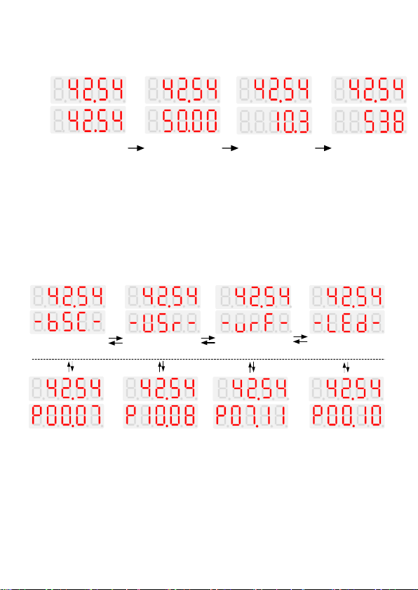
The menu is divided into four types: standard mode, user-defined mode, calibration
mode, LED setting mode.
◆Standard Mode(-bSC-)
If the access authority (P00.01) is the standard, all function codes mentioned in the
VFD500 user manual can be accessed.
If the access authority (P00.01) is the end user (in the state where the user password is

5
locked), Then only individual function codes can be accessed.
◆User-defined mode(-USr-)
In this menu mode, only 20 groups of user-defined parameters are displayed.
◆calibration mode(-vrF-)
In this menu mode, only the parameters that differ from the factory values are
displayed.
Note: The forward rotation of the knob will display the next function code, the reverse
rotation will not respond.
◆ LED setting mode(-LEd-)
In this mode, PAr.00-PAr.03 can be set and viewed. This parameter belongs to the
keyboard's own parameters and will be automatically stored in the keyboard's eeprom
before power off.
Function Code
Name
Description
PAr.00
version number
-Can view the current LED
keyboard software version
number.
PAr.01
Monitoring parameters
-Turn the knob to set the first line
of monitoring parameters.
PAr.02
Automatically save
current settings when
power off
0:Automatic quick save setting
after power off
1:Automatic save setting without
power off

6
PAr.03
Communication error
statistics
-Count the number of
communication errors since the
keyboard was powered on
Table 1-2 PAr.xx function code details in LED setting mode
3. Operation example
The three switchable interfaces after power-on, the respective operations are as
follows:
The interface can be switched by the [ESC] button.
.
Monitoring
status Function code
selection status Menu mode
Select status
ESC
ESC ESC
After
power on
(1) Monitoring status interface
When the monitoring status interface is stopped, the default monitoring parameters are
determined by function code P21.12, and the default monitoring parameters are
determined by P21.11 during operation. At this time, you can switch and view the set
monitoring parameters through the [SHFIT] butt

7
Monitoring
status
SHIFT (Monitoring
quantity 2) (Monitoring
quantity 3)
(Monitoring
quantity 4)
(Monitoring
quantity 1) SHIFT SHIFT
(2) Menu list interface
【UP、DOWN、SHIFT】
UP
DOWN
(Standard
mode)
(User-defined
mode) (Checkout mode) (LED setting
mode)
【UP、DOWN、SHIFT】【UP、DOWN、SHIFT】 【UP、DOWN、SHIFT】
ESC ENTER ESC ENTER ESC ENTER ESC ENTER
Menu list
UP
DOWN
UP
DOWN
(3) Function code selection interface

8
Function code
selection
status
parameter
Edit/View status
【UP/DOWN/SHIFT】
ESC ENTER
【UP/DOWN】
【UP/DOWN/SHIFT】【UP/DOWN/SHIFT】【UP/DOWN/SHIFT】
ESC ENTER ESC ENTER ESC ENTER
【UP/DOWN/SHIFT】 【UP/DOWN/SHIFT】【UP/DOWN/SHIFT】
Note:
1)Dual-line monitoring cannot monitor "32-bit data" and "binary data".
2)In the monitoring state of the second line, rotate “UP and DOWN” to set the
frequency or torque in real time. For details, see function code P21.13 (the default
factory setting is P00.07, and the rotary knob will take effect immediately after the
change).
4. digital tube display
◆Display of decimal data
16 digits:
The display range for unsigned numbers is 0 to 65535 (excluding the decimal point),
the display range for signed numbers is -9999 to 32767 (excluding the decimal point),
and negative numbers less than -9999 will be displayed as -9999.

9
32 digits:
Dot1 is used to distinguish between the upper and below screens, Light up means the
up screen displayed (high 5 digits),Off means down screen displayed (lower 5 digits).
The display range of 32-bit unsigned numbers is 0 ~ 4294967295.
As shown 4294967295:
Dot1
◆Binary data display
Binary numbers currently only support 16 digits, which are displayed on the up and
down screen.
The leftmost digital tube is used to distinguish the up and down screens: the top
segment lights up to indicate the up screen, and the bottom segment lights up to
indicate the down screen.
Excluding the leftmost digital tube, from top to bottom are Bit15 ~ Bit0. The upper
segment is lit to indicate 1, and the lower segment is lit to indicate 0.

10
Lower screen, lower 8
digits
Upper screen, high 8
digits
bit1=1
bit0=0
bit15=0
◆Parameter attribute identification
The leftmost digital tube of the editable parameter displays "P"; The leftmost digital
tube of the read-only parameter displays "r", Show as the picture:
“P”means can be edit
“r”means read only
◆Specific symbol
In some states, the digital tube will display a specific symbol. The meaning of specific
symbols is shown in the table below:
Symbol
Significance
tUnE
Motor parameter self-learning
bUSY
Processing parameter read and write requests
End
-Indicates that the parameters have been changed
and saved to EEPROM
-The mission has been completed

11
Er.xxx
-Fault code, "XXX" is the fault type, For details,
please refer to "VFD500 User Manual
Troubleshooting"
Cr.xxx
Communication failure code, "XXX" is the failure
type, Cr.001-Cr005 represents the data error, Cr.006
is the communication timeout, and Cr.007 is the CRC
check error.
PAr.xxx
The LED's own parameters can be set in the "LEd"
menu mode, see "LED Setting Mode (-LEd-)" for
details.
Table 3-1 digital tube display symbols and meanings
Other manuals for VFD500 Series
2
Table of contents