Veilux SVEX-T500A User manual

Explosion Proof User Manual
SVEX-T500A

2
Please carefully read this Instruction Manual before installation and use.
1. Installation
1. Please carefully read this Instruction Manual and follow the warnings before installation
and use.
2. Be sure to cut off the power supply before maintenance and repair of the equipment.
3. Do not turn on the equipment in any place where there is oil smoke, excessive dust, high
temperature or condensation; otherwise, it may cause reduced image definition.
4. Please install the cables or optical cables correctly according to the requirements of this
Manual; otherwise, it may cause faults.
5. During maintenance of the equipment, pay attention to the protection of flameproof
surface; avoid metal chips or other foreign matters from entering the equipment.
6. Do not attempt to disassemble or modify the equipment.
2. Environment Protection
Our products may contain parts which pollute the environment, such as circuit board,
electronic components, plastic products and lubricating grease, etc. During maintenance
or scrapping of the equipment, pay attention to collect and control such pollution sources;
do not discard them arbitrarily; hand them over to the relevant environment protection
department for disposal so as to avoid adverse influence on the environment.
SVEX-T500A Explosion Proof Camera User Manual.
Safety Notes

3
1. Overview...........................................................................4
2. Technical Index.................................................................5
2.1 Model Description....................................................5
2.2 Certification..............................................................5
2.3 Model.......................................................................5
2.4 Electrical Index.........................................................5
2.5 Mechanical Index.....................................................6
2.6 Ambient Condition....................................................6
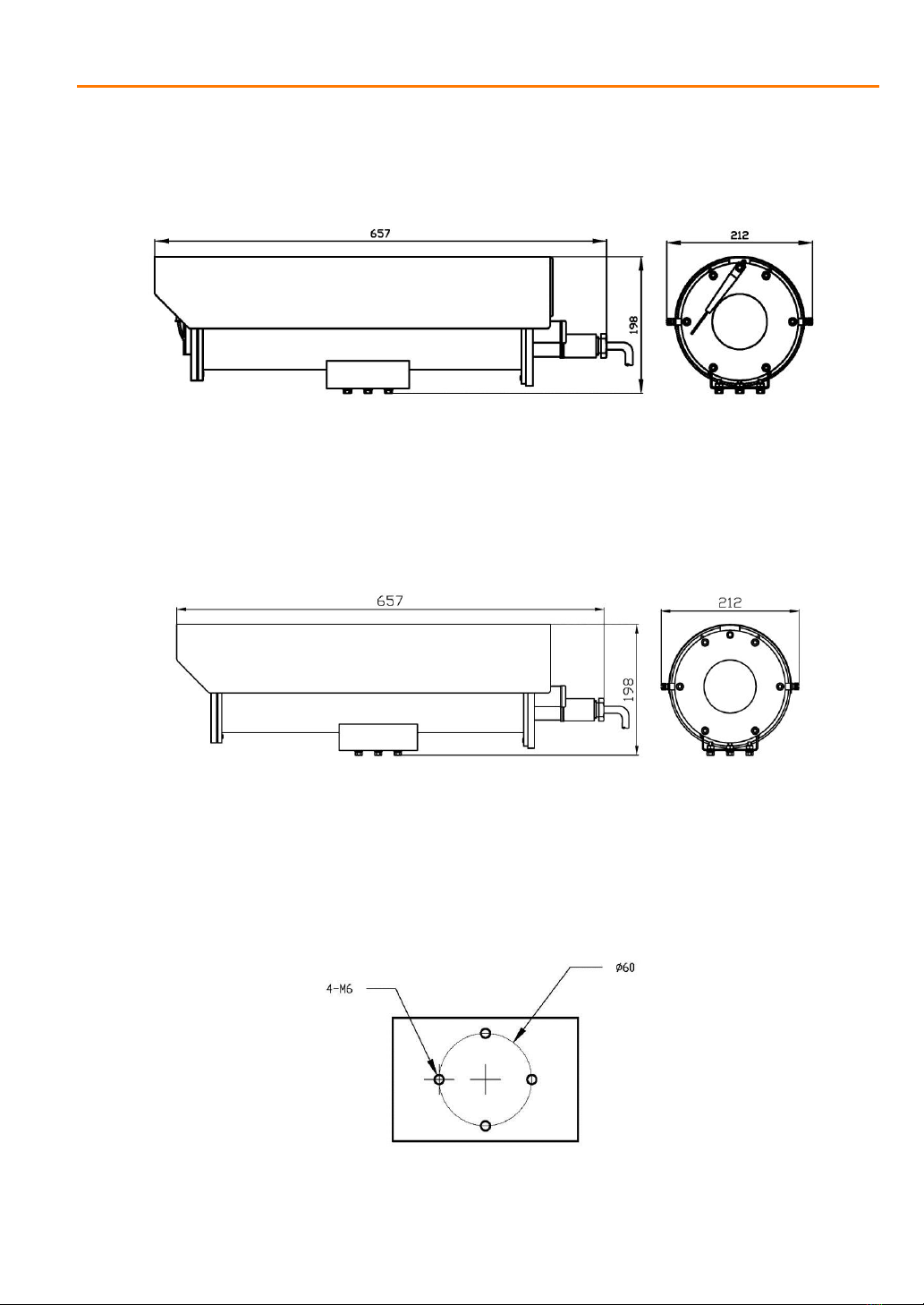
2.7 Product Dimension...................................................6
2.8 Installation Dimension..............................................7
3. Installation.........................................................................8
3.1 Installation of Camera and Lens ..............................8
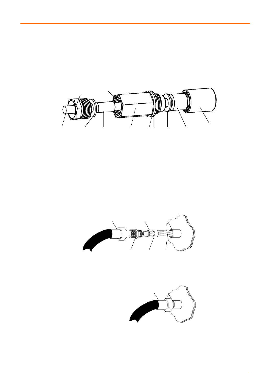
3.2 Cable Treatment......................................................9
3.2.1 Cable Treatment at Delivery.........................................9
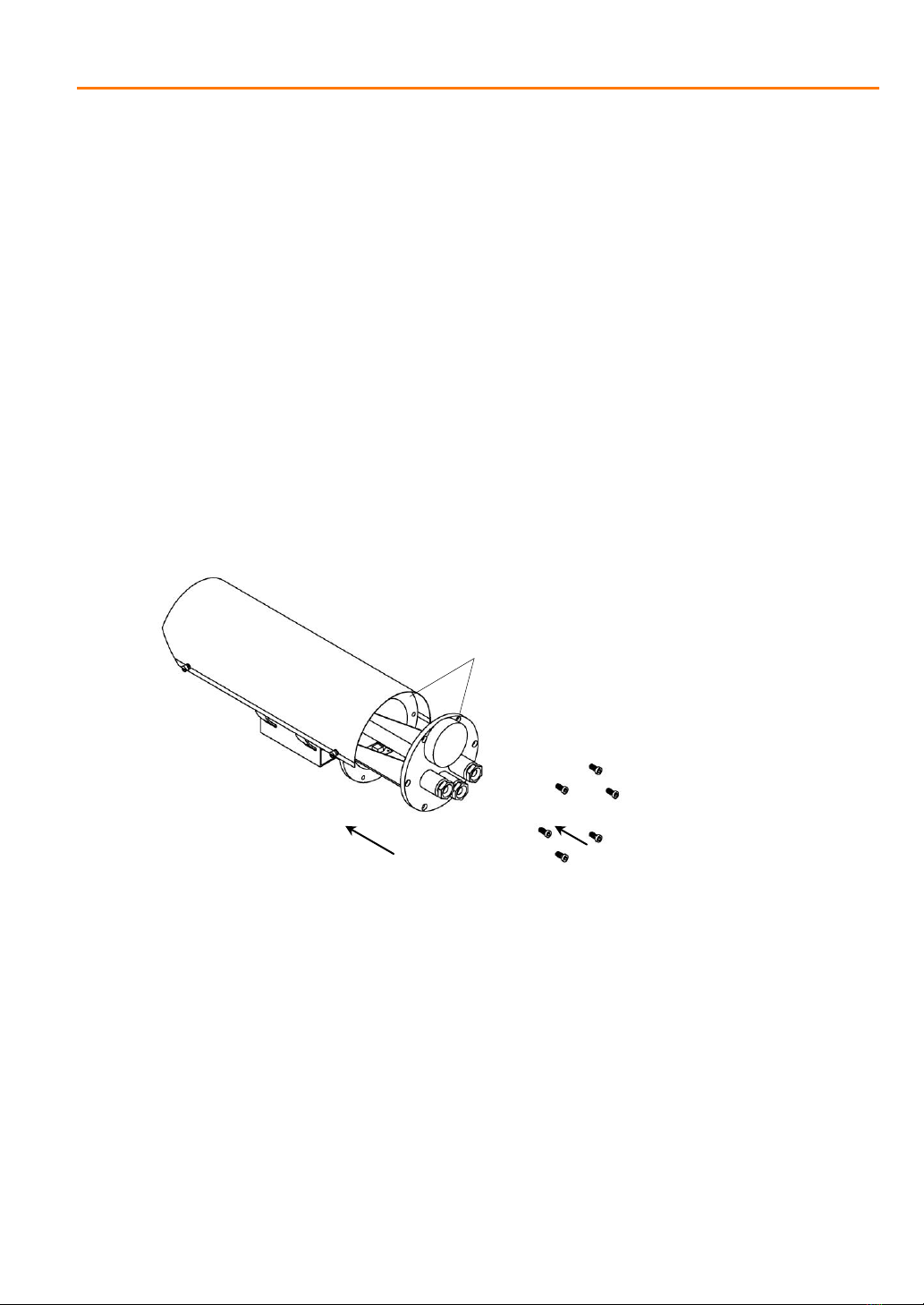
3.3 Installation of Housing Barrel.................................10
3.4Installation of Housing onto Electric Pan-tilt...........11
3.5Installation of Housing onto Fixed Support.............11
3.6Installation Precautions..........................................12
4.Description of Explosion-proof Structure.........................13
5.Troubleshooting ..............................................................13
6.Transportation and Storage ............................................14
7.Installation Accessories...................................................14
8.Quality Assurance...........................................................15
9.Declaration......................................................................15
Appendix I: Lens Adjustment ..............................................15
Appendix II: Use of Desiccant.............................................16
Appendix III: Content Reference Table of Toxic and
Hazardous Substances or Elements...................................17
SVEX-T500A Explosion Proof Camera User Manual.
Content

4
Designed and manufactured strictly according to the standards such as GB3836.1-2010
Explosive atmospheres - Part 1: Equipment - General requirements, GB3836.2-2010
Explosive atmospheres - Part 2: Equipment protection by flameproof enclosure “d”,
GB12476.1-2000 Electrical apparatus for use in the presence of combustible dust - Part 1-1:
Electrical apparatus protected by enclosures and surface temperature limitation - Specification
for apparatus, EN60079-0:2009 Explosive atmospheres - Part 0: Equipment - General
requirements, EN60079-1:2007 Explosive atmospheres - Part 1: Equipment protection by
flameproof enclosure “d”, and EN 60079-31:2009 Explosive atmospheres - Part 31: Equipment
dust ignition protection by enclosure "t", SVEX-T500 series explosion-proof camera has
the enclosure of all stainless steel structure with the level of protection up to IP66, and can
be widely used in the fields of petroleum, chemical industry, wharf, port, mine, aerospace,
aviation, military industry and grain processing, etc.
SVEX-T500 series explosion-proof camera has 4 specifications, including long type in
which zoom lens cameras can be installed, and short type in which fixed lens cameras or
integrated cameras can be installed.
Relevant technical data, patterns and prototypes of SVEX-T500 series explosion-proof
camera (hereinafter referred to as the camera) have been reviewed to be qualified by
the China National Quality Supervision and Test Centre for Explosion Protected Electrical
Products (CQST).
SVEX-T500A Explosion Proof Camera User Manual.
1- Overview

5
2.1 Model Description
SV T500 A
B为短形护
Design serial number
Product code
Company code
2.2 Certification
Explosion-proof mark II 2 GD Ex d II C T6 Gb
Ext III C T80°C Db
2.3 Model
SVEX-T500A
2.4 Electrical Index
Input voltage
Input voltage range
Operating current
Camera power supply
Heater
Power consumption
Electrical connection
Explosion-proof camera, with wiper, long type
220VAC/110VAC/24VAC 50/60Hz(24V is a special type;
please specify when ordering)
±10%
≤2A
12VDC (provided by external equipment)
Started at the temperature below -10ºC±5ºC
30W
2-core cable for power supply
4-core cable for lens control
Video cable for video signal output
Blank: with wiper / -1: without wiper
/A: with wiper / -1/A: without wiper
SVEX-T500A Explosion Proof Camera User Manual.
EX
2- Technical Index

6
2.5 Mechanical Index
SVEX-T500A
Material
Level of protection
Outside dimension
Inside dimension
Sight window
Area of sight window
Weight / Shipping weight
Number of outlet holes
Thread size of outlet holes
Installation mode
2.6 Ambient Condition
Atmospheric pressure 80~110KPa
Ambient temperature -40ºC~+60ºC
Relative humidity 95%RH (+25ºC)
SVEX-T500A Explosion Proof Camera User Manual.
Stainless steel 304 or 316L
IP66
657(L) x 198(H) x 212(W) mm
/[+[:PP
15mm thick
Φ80mm
16Kg / 18Kg
3
G-3/4”or M25×1.5
Electric pan-tilt, semi-fixed
pan-tilt, fixed support

7
Figure3. Outside Dimension of SVEX-T500A Explosion-proof All-weather Camera Housing
2.8 Installation Dimension
Figure 3. Fixing Holes at the Bottom of Housing
SVEX-T500A Explosion Proof Camera User Manual.
2.7 Product Dimension
Figure 1. Outside Dimension of SVEX-T500A Explosion-proof All-weather Camera Housing

3.1 Installation of Camera and Lens
Carefully read the instruction manual before installation to learn whether the CCD
specifications and interface forms of the lens and camera are consistent; the 1/3 or 1/2 inch
lens can be installed in the 1/3 inch CCD camera, and only the 1/2 inch lens can be installed
in the 1/2 inch CCD camera, otherwise, vignette may be generated on the picture edge.
Figure 4. Lens Installation
After the lens and camera are installed, adjust the back focal length of the camera, and then
observe the clear degree of test card on the monitor.
Install the properly debugged lens and camera on the drawer plate of the housing, and adjust
their front and rear positions to ensure that the picture edge has no vignette after the barrel is
mounted.
Figure 5. Installation of Camera and Prime Lens Figure 6. Installation of Camera and Zoom Lens
on Drawer Plate on Drawer Plate
Tighten after
insertion
SVEX-T500ASVEX-T500A
Adjust the front
and rear
positions
Fasten with screw
Fasten with screw
Adjust the front
and rear
positions
SVEX-T500A Explosion Proof Camera User Manual.
3- Installation
8

9
3.2 Cable Treatment
3.2.1 Cable Treatment at Delivery
Figure 3.3.1 Structure of Standard Packing Box at Delivery
3.2.2 Use of Explosion-proof Flexible Tube
a. As shown in Figure 7, attach the explosion-proof flexible tube assembly onto the cable; after
removing the hold-down nut, reserve standard gasket and rubber ring (it is also OK to use
spare parts in the packaging box).
Figure 7.
b. As shown in Figure 8, first tighten the thread joint, and then tighten the explosion-proof
Explosive-proof
seal joint Flat
gasket Gasket Nut seatRubber
seal ring
Outgoing cable Rubber
gasket
HPS89-01
epoxy
resion
Hold-down nut
Bakelite
gasket
A.B-type cable gland packing filled inside
Explosion-proof flexible tube
Thread joint Rubber ring
Gasket
Outgoing cable
Outlet hole
SVEX-T500A Explosion Proof Camera User Manual.
flexible tube.
Outlet hole
Explosion-proof flexible tube
Figure 8.

10
3.3 Installation of Housing Barrel
The flameproof surface of the housing fits quite closely since the explosion-proof grade is
high. During installation, especially pay attention to protecting the flameproof surface;as
shown in the figure,the rear cover and the rear side of the barrel are flameproof surfaces,
which shall not be impacted or scratched during installation.
Figure 11. Careful Installation of Housing Rear Cover
An insulating spacer is provided between the drawer plate and the rear cover plate in the rear
cover assembly, and its insulation performance shall be paid attention to in case
disassembling is required; after assembling, measure its insulating resistance to ensure that it
is not less than 100MΩ. There is an externally grounded bolt in the center of the rear cover,
which shall be reliably connected to the earth when the equipment is installed.
Flameproof surface
Apply force uniformly
Fasten rear cover
with screws
SVEX-T500A Explosion Proof Camera User Manual.

11
Figure 12. Pay Attention to Insulating Layer between Rear Cover and Drawer Plate
Insulating layer
SVEX-T500A Explosion Proof Camera User Manual.
Note:
1. S/N 1 consists of 2 line groups. One group is for heating (red, 0.5mm2); the other group is
the common motor terminal (white, yellow);
2. S/N 2 consists of 2 line groups. One group is for heating (red, 0.5mm2); the other group is
the jumper from No. 2 terminal to No. 3 terminal (white);
3. S/N 3 consists of 2 line groups. One group is for the wiper limit switch (white); the other
group is the jumper from No. 2 terminal to No. 3 terminal (white);
4. S/N 4 consists of 3 line groups. One group is for the capacitor (red), one group is for the
motor (0.14mm2, red), and the other group is for the wiper limit switch (brown).
3.4 Installation of Housing onto Electric Pan-tilt
Please refer to the instruction manual of electric pan-tilt.
3.5 Installation of Housing onto Fixed support
Figure 14. SVEX-T500A Support Installation Diagram

12
3.6 Installation Precautions
Check the following items before installing the product, and the product cannot be used if
it is non-conforming.
a. Whether there is explosion-proof certificate number;
b. Whether the explosion-proof mark applies to the environment of explosive gas
mixture;
c. Whether all explosion-proof parts are free from cracks and defects affecting the
explosion-proof performance.
Correctly select the cable, ensure that the diameter of lead-in cable matches with the bore
diameter of rubber seal ring, select the minimum cable OD as per the mark on the end
face of the rubber seal ring, and guarantee that the gaps between the rubber seal ring and
the cable as well as the rubber seal ring and the lead-in device meet the explosion-proof
requirement after the hold-down nut is tightened.
Set the nameplate and the warning sign “No Opening with Power” in an obvious position
on the surface of the product.
During wiring, select the seal ring with inner bore of Φ10 and characters “≥Φ9.5” cast on
SVEX-T500A Explosion Proof Camera User Manual.
the end face, and select the cable of which the outer diameter matches with the internal
bore diameter of the seal ring, as shown in the figure.
Figure 15. Seal Ring Diagram
≥Φ9.5

13
Failure Cause Solution Remark
Wiper
problem Stuck wiper Return to Veilux for
repair
Dead corners Adjust the wiper shaft
No image
Open-circuit power
supply Check the wiring
Open-circuit signal line Check the wiring
Damaged camera Replace the camera Return to Veilux
for repair
Faulty lens Replace the lens
SVEX-T500A Explosion Proof Camera User Manual.
DYI
DYI
DYI
Return to Veilux
for repair
4-Description of Explosion-proof Structure
Various special circumstances are adequately considered during structural design, so that
no explosion will occur in the environment full of explosive mixture outside the equipment
if sparks are generated in the equipment; moreover, the explosion-proof performance of
the equipment is guaranteed from the following aspects: enclosure strength, gap between
components, and highest surface temperature limitation of enclosure.
The explosion-proof enclosure after finish machining must be able to withstand the
hydraulic test pressure specified in GB3836.2: 2.0MPa, not less than 10s, judged as
qualified in case of no water dripping and intact structure.
The highest surface temperature of enclosure shall not exceed +80ºC during normal
operation.
The lead-in device for the camera is fastened with the hold-down nut.
The sight window of the camera is made of tempered glass, and thus can withstand the
impact and thermal shock tests.
5- Troubleshooting

14
The packaged product can be transported by various methods in the condition that it is
protected from direct exposure to rain and snow; it can be stored for more than one year in the
environment with the temperature of 0ºC~+40ºC and the relative humidity of not more
than 90%.
At delivery, 10mm rubber seal ring is mounted in the outlet hole of the camera, and
10mm blocking core and hold-down nut are mounted in the hole without threaded line.
Provide one 8mm rubber seal ring, one 12mm rubber seal ring, and one portion of
desiccant; provide one 1/4″ copper screw, one 6mm copper screw and one 12mm copper
screw for the housing. Other accessories: (to be ordered separately)
Figure 16. SVEX-M1 Support
SVEX-M1 Side View
SVEX-M1 Top View
SVEX-M1 Front View
SVEX-T500A Explosion Proof Camera User
Manual.
6- Transportation and Storage
7- Installation Accessories

15
SVEX-T500A Explosion Proof Camera User
Manual.
8- Quality Guarantee
For any camera produced by Veilux, we promise a one year to repair warranty.
During Guarantee period, we supply free service except following situations:
„ User does not operate as manual book requires
„ User un-install the whole product by themselves
„ Lightning or Act of God
If there are additional agreements between Veilux and buyer, then agreements shall
be strictly done
9- Company Commitment
„ Veilux owns the final design changing and final specification rights and no responsibility to
inform user.
„ This manual book belongs to Veilux rights, without permits or any book inform, any company
or
private copy of whole or part of the book shall be prohibited.
Appendix I: Lens Adjustment
Aperture ring
Zoom ring
Focusing ring
BNC port for video output
Power input
Manual three-variable lens

16
Take the computar H2Z4516CS-2 lens which has three adjustable rings as an example:
“OPEN” and “CLOSE” are marked on the aperture ring, and the aperture ring can be directly
rotated to adjust the aperture; “OPEN” means increasing the aperture, and “CLOSE” means
decreasing the aperture. In the environment with weak light, increase the aperture to improve
the viewing effect; in the environment with ample light, properly decrease the aperture, so that
the screen will not turn white. In addition, increasing the aperture makes the depth of field get
smaller, and decreasing the aperture makes the same get larger.
A locking screw is set for the zoom ring and focusing ring respectively. Before adjustment,
rotate the screw anticlockwise, so that the zoom and focusing rings are in the adjustable state;
after adjustment, properly lock the screw.
“W” and “T” are marked on the zoom ring, and mean “WIDE” and “TELE”; adjusting towards
the “W” direction increases the view angle of the lens to the maximum, so “W” means wide
angle; adjusting towards the “T” direction decreases the view angle, and thus farther views can
be seen.
“∞” and “N” are marked on the focusing ring, and mean “Infinite”and “NEAR” respectively;
focusing is adjusted as per the distance (i.e., object distance) of the observed view, till the
scenery is clear.
Please don’t touch the surface of the lens when operating it, and please clean the dust or
pollutants (if any) on the lens with special cleaning cloth.
SVEX-T500A Explosion Proof Camera User Manual.
Appendix II: Use of Desiccant
The desiccant bag is included in the accessories packed along with the product. Place
the desiccant in the equipment cavity after installation and electrical connection of the
equipment. Please pay attention to the placement position: keep away from driving
and electrical connection parts, and be relatively static and tight, so as to avoid the line fault
or driving fault due to absorption saturation of the desiccant.

17
SVEX-T500A Explosion Proof Camera User Manual.
Appendix III: Content Reference Table of Toxic and Hazardous
Substances or Elements
Part Name
Toxic and Hazardous Substances or Elements
Lead
(Pb)
Mercury
(Hg)
Cadmium
(Cd)
Hexavalent
Chromium
(Cr
6+
)
Polybrominated
Polybrominated
Biphenyls
(PPB)
Diphenyl
Ethers
(PBDE)
Stainless steel
304 ○○ ○ ○ ○ ○
Die casting ○ ○ ○ ○ ○ ○
Circuit board ○ ○ ○ ○ ○ ○
Core ○ ○ ○ ○ ○ ○
Connecting
wire ○ ○ ○ ○ ○ ○
Power supply
(if any) ○ ○ ○ ○ ○ ○
Support (if
any) ○ ○ ○ ○ ○ ○
Accessories ○ ○ ○ ○ ○ ○
Note:
1. ○ indicates that the content of the toxic and hazardous substance or element in all the
homogeneous materials of the part is below the concentration limit requirement as
described in SJ/T 11363-2006.
2. ×indicates that the content of the toxic and hazardous substance or element in at least
one homogeneous material of the part exceeds the concentration limit requirement as
described in SJ/T 11363-2006. As long as the product is used properly within the
environment-friendly use period, these substances or elements will not leak or mutate,
and will not result in any bodily injury or damage to the property of the user. Do not
dispose of these substances or elements by yourself; please hand them over to the
relevant department designated by the government for recycling according to the
government decree.
Table of contents
Popular Camera Accessories manuals by other brands

Avigilon
Avigilon DOME-OD-BASE installation guide

ORION TELESCOPES & BINOCULARS
ORION TELESCOPES & BINOCULARS AZ-4 instruction manual

milleteknik
milleteknik NOVA FLX M quick start guide

Major tech
Major tech MT190 instruction manual

Filmcity
Filmcity FC-A7S-KIT instruction manual

Ikelite
Ikelite Olympus C-8080 instruction manual

Lucent Technologies
Lucent Technologies KS-20472 product manual

Rollei
Rollei Fotopro FPH-53P instructions

Accessory Power
Accessory Power USA GEAR TrueSHOT GRTSDBA100BKEW user guide

Sony
Sony SRMASTER SR-PC4 Operation manual

REXROTH
REXROTH HAB 6X Series operating instructions

Sony
Sony VCT-80AV operating instructions