Velleman K4401 User manual
Total solder points: 155
Difficulty level:
beginner 1þ2o3o4o 5oadvanced
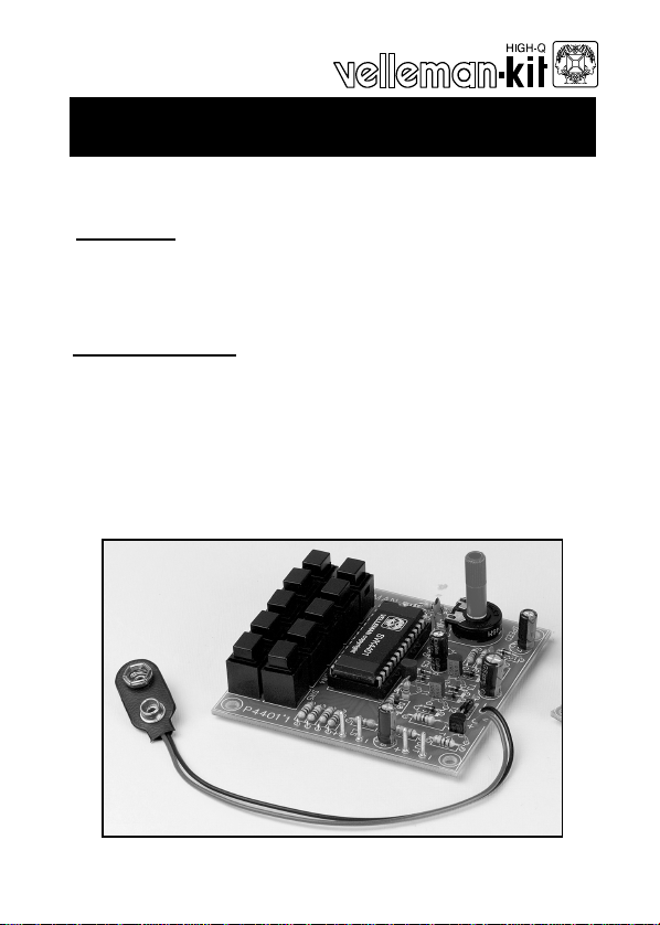
K4401
Sound generator
ILLUSTRATED ASSEMBLY MANUAL H4401IP-1
þ10 different Sounds : Sirens, Machine gun, Mortar, Car engine…
þAdjustable sound speed.
þPush-button keyboard.
Specifications :
—Loudspeakers output : 8 ohm/1W
—Line output : 1VRms.
—Power supply : 8 -10VDC (9v battery).
—Max. current consumption : 100mA
—Secured against polarity reversal of the supply voltage.
Modifications reserved.
Features:

2
VELLEMAN Components NV
Legen Heirweg 33
9890 Gavere
Belgium Europe
www.velleman.be
www.velleman-kit.com

3
1. Assembly (Skipping this can lead to troubles ! )
Ok, so we have your attention. These hints will help you to make this project success-
ful. Read them carefully.
1.1 Make sure you have the right tools:
•A good quality soldering iron (25-
40W) with a small tip.
•Wipe it often on a wet sponge or cloth, to keep it clean; then apply solder to the
tip, to give it a wet look. This is called ‘thinning’ and will protect the tip, and en-
ables you to make good connections. When solder rolls off the tip,
it needs cleaning.
•Thin raisin-core solder. Do not use
any flux or grease.
•A diagonal cutter to trim excess wires. To avoid injury
when cutting excess leads, hold the lead so they
cannot fly towards the eyes.
•Needle nose pliers, for bending leads, or to hold components in
place.
•Small blade and Phillips screwdrivers. A basic range is fine.
For some projects, a basic multi-meter is required, or
might be handy
1.2 Assembly Hints :
⇒Make sure the skill level matches your experience, to avoid disappointments.
⇒Follow the instructions carefully. Read and understand the entire step before you
perform each operation.
⇒Perform the assembly in the correct order as stated in this manual
⇒Position all parts on the PCB (Printed Circuit Board) as shown on the drawings.
⇒Values on the circuit diagram are subject to changes.
⇒Values in this assembly guide are correct*
⇒Use the check-boxes to mark your progress.
⇒Please read the included information on safety and customer service
* Typographical inaccuracies excluded. Always look for possible last minute manual
updates, indicated as ‘NOTE’ on a separate leaflet.
0.000
Assembly hints
4
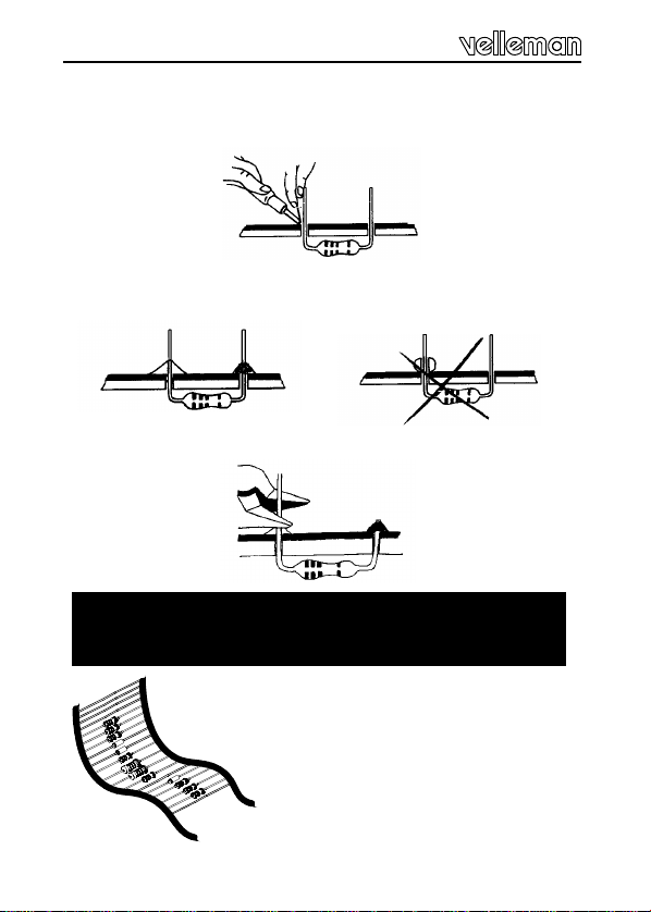
1.3 Soldering Hints :
Mount the component against the PCB surface and carefully solder the
leads
Make sure the solder joints are cone-shaped and shiny
Trim excess leads as close as possible to the solder joint
REMOVE THEM FROM THE TAPE
ONE AT A TIME !
AXIAL COMPONENTS ARE TAPED IN THE CORRECT
MOUNTING SEQUENCE !
Assembly hints

IPESF SDK NDGB FNL
C
O
D
E
CODICE
COLORE CODIGO
DE CORES CODIGO
DE COL-
ORES
VÄRI
KOODI FÄRG
SCHEMA FARVE-
KODE FARGE-
KODE FARB
KODE COLOUR
CODE CODIFI-
CATION
DES COU-
LEURS
KLEUR
KODE C
O
D
E
0Nero Preto Negro Musta Svart Sort Sort Schwarz Black Noir Zwart 0
1Marrone Castanho Marrón Ruskea Brun Brun Brun Braun Brown Brun Bruin 1
2Rosso Encarnado Rojo Punainen Röd Rød Rød Rot Red Rouge Rood 2
3Aranciato Laranja Naranjado Oranssi Orange Orange Orange Orange Orange Orange Oranje 3
4Giallo Amarelo Amarillo Keltainen Gul Gul Gul Gelb Yellow Jaune Geel 4
5Verde Verde Verde Vihreä Grön Grøn Grønn Grün Green Vert Groen 5
6Blu Azul Azul Sininen Blå Blå Blå Blau Blue Bleu Blauw 6
7Viola Violeta Morado Purppura Lila Violet Violet Violet Purple Violet Paars 7
8Grigio Cinzento Gris Harmaa Grå Grå Grå Grau Grey Gris Grijs 8
9Bianco Branco Blanco Valkoinen Vit Hvid Hvidt Weiss White Blanc Wit 9
AArgento Prateado Plata Hopea Silver Sølv Sølv Silber Silver Argent Zilver A
BOro Dourado Oro Kulta Guld Guld Guldl Gold Gold Or Goud B
5%
4K7= ( 4 - 7 - 2 - B )
1%
4K7= ( 4 - 7 - 0 - 1 - 1 )
COLOR= 2… 5
COLOR= 2...5

6
Construction
The ideal equipment for disc-jockeys, jingles for free radios
or simply as an attention drawer. All sounds have been
realised by means of a programmed micro-processor. The
sounds generator has an output for direct connection of a
loudspeaker and a line output for connecting a mixing
panel or an amplifier.
The following effects can be called directly through push
buttons:
—Machine-gun (random number of shots with bullet impact).
—European siren.
—Phasor gun (STAR-WARS-like machine-gun).
—Racing-car engine (increase/decrease the number of r.p.m.).
—Car tire screech
—Explosion.
—Mortar shot followed by an explosion.
—Tune: "Wild charge tune".
—Tune: "Snake charmers tune".
—U.S.A. siren.
7
qD1 : 1N4148
qD2 : 1N4148
qD3 : 1N4148
qD4 : 1N4148
qD5 : 1N4148
qD6 : 1N4148
qD7 : 1N4148
qD9 : 1N4148
qD10 : 1N4007
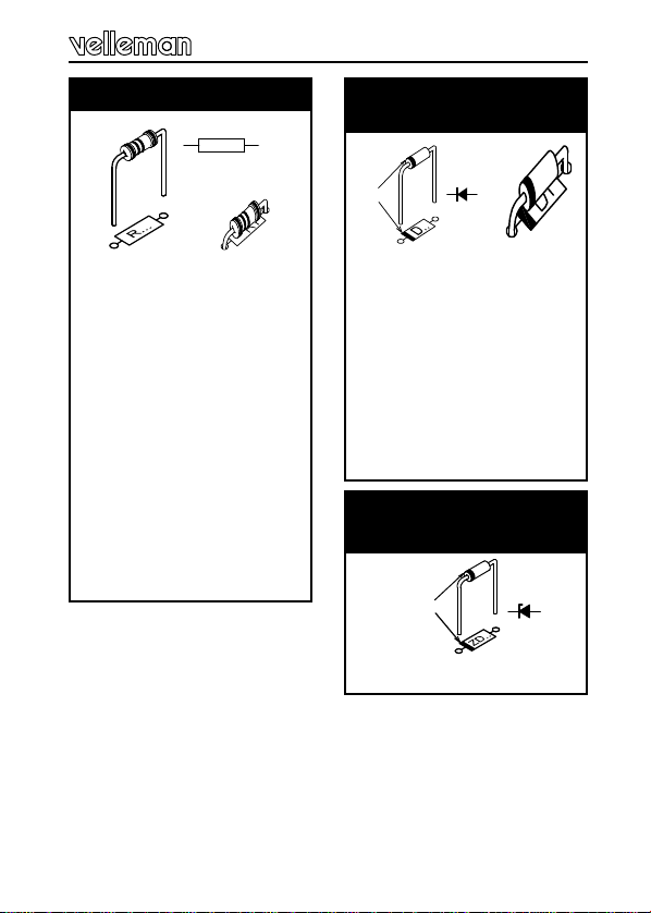
2. Diodes. Watch the
polarity !
D...
CATHODE
qR1 : 4K7 (4-7-2-B)
qR2 : 330 (3-3-1-B)
qR3 : 2M2 (2-2-5-B)
qR4 : 2K2 (2-2-2-B)
qR5 :10M (1-0-6-B)
qR6 : 27 1/2W (2-7-0-B)
qR7 :470 1/2W (4-7-1-B)
qR8 :1K (1-0-2-B)
qR9 :10K (1-0-3-B)
qR10:10K (1-0-3-B)
qR11:10K (1-0-3-B)
qR12:10K (1-0-3-B)
qR13:10K (1-0-3-B)
qR14:10K (1-0-3-B)
qR15: 3K3 (3-3-2-B)
1. Resistors
R...
Construction
qZD1: 5,1V
3. Zenerdiode
Watch the polarity !
ZD...
CATHODE

8
Construction
qC1 : 22pF (Ceramic)
qC2 : 100nF (104)
qC3 : 100nF (104)
qC4 : 100nF (104)
6. Ceramic Capacitors
C...
qIC1 : 28P
4. IC socket, Watch the
position of the notch!
Fit the diode D8 vertically
and with one lead connected
for the present.
Mount one side of R6
vertically on the anode side
of D8
qR16 : 470 1/2W
5. Correction network
D8
D8
D8 D8
Then connect the free
extremities of each diode-
resistor pair together and
cut them.
D8
9
qT1 : BC557 or eq.
qT2 : BC557 or eq.
qT3 : BC557 or eq.
qT4 : BC517 or eq.
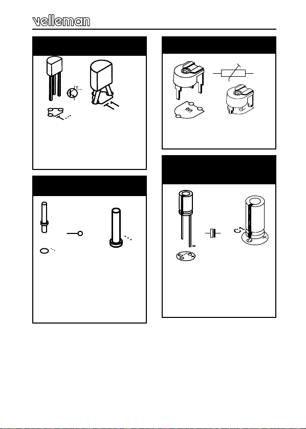
7. Transistors.
qC5 :1µF
qC6 :47µF
qC7 :47µF
qC8 :100µF
10. Electrolytic capacitors.
Watch the polarity !
C...
qRV1 :47K
9. Trim potentiometer
qOUT +
qOUT -
qLS +
qLS -
q+V
q-V
8. PCB-pins
Construction
RV1

10
qSW1
qSW2
qSW3
qSW4
qSW5
qSW6
qSW7
qSW8
qSW9
qSW10
11. Pushbuttons.
qIC1: VK4401
Programmed PIC16C55A
12. IC, Check the
position of the notch !
Construction
Fit the potentiometer axe.
13. Potentiometer axe

11
FLoudspeaker & on/off switch are not included !
Inspect the complete assembly once more
before applying power to the unit !
+
-
-
+
-
+
LS
OUT
9V
LINE
OUT
-+
LOUDSPEAKER
8 OHM / 1 WATT
-
+
9V
BATTERY
K4401
ON/OFF
Hook-up diagram
14. Hook-up diagram
Black
Red

12
—Turn the potentiometer to its centre position.
—Connect a loudspeaker (8 ohm / 1Watt min.) between
the points LS.
—Connect a power supply (9VDC) or a 9V battery bet-
ween the points +V and -V.
—Pressing the different push buttons now causes the
respective effects to be produced.
FATTENTION: With some of the effects (e.g. sirens,
car engine) it's necessary to keep the push button
pressed. The speed of the effects can be changed
(optimized) by turning the potentiometer.
The OUT output allows you to extra amplify the
sounds or to connect them to a mixing panel. In this
case you possibly can disconnect the loudspeaker.
Thanks to the position of the push buttons and of
the potentiometer, this circuit can be built into a
plastic housing or the pcb be mounted behind a pa-
nel very easily.
Test and usage
15. Test and usage

13
16. PCB layout.
PCB
SW6 SW7 SW8 SW9
SW1 SW2 SW3 SW4
C4
R14
D5
D9
T3
D6
R3
D4
T2
D7
D2
D3
SW5
SW10
R10
R11
R12
R13
D1
C2
RV1
R1
C1
R9
D10
C8
R2
ZD1
C7
R4
R8
R7
C6
R5
C3
R15
D8
T1
T4
C5
IC1
1
+-
-
+
-
+
LS
OUT
9V
VELLEMAN
P4401'1
SPEED
R6
14
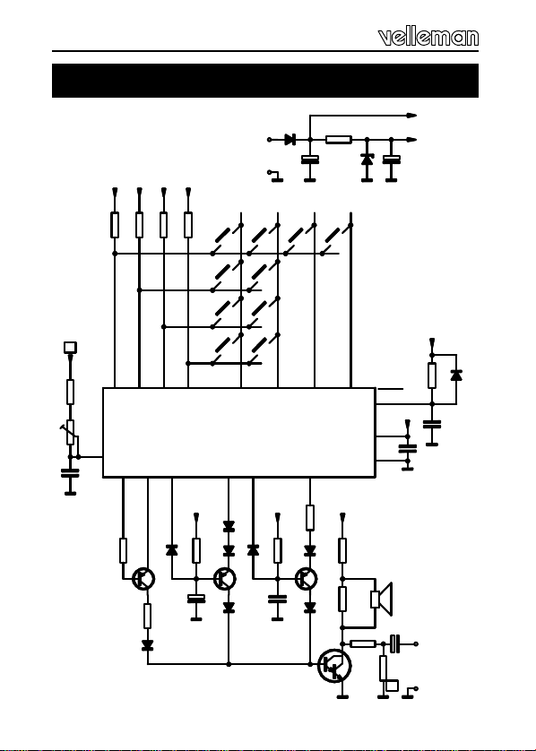
17. Schematic diagram.
Schematic diagram
R5
C3
+V
D9
RC6RC7
25 242021
RC3 RC2
D2
+V
R3
T2
D4
D3
C5 D7 D6
D8
T1
R16
18 19
RC1
RC0
T4
R7
R6
+V1
R4
R8
LS
C6 +
-
LINE
OUT
IC1
1
2
3
4
5
6
7
8
9
10
WILD CHARGE
MORTAR & EXPL.
EXPLOSION
TIRE SCREECH
SNAKE CHARMERS
ENGINE UP/DOWN
PHASOR GUN
EUROP. SIREN
MACHINE GUN
USA SIREN
+
-
D10
C8
R2
ZD1 C7
+V
+V1
9VDC
R10
+V +V
R11
+V
R12
+V
R13
9
8
7
6
4
3
2
1
510
RA3 RA2 RA1 RA0 RB3 RB2 RB1 RB0
9 8 7 6 13 12 11 10
C4
+V
R14 D1
C2
+V
28
2
4
MCLR
VCC
VSS
C1
R1
RV1
+V
27
OSC1
SPEED
R9
D5
T3


16
VELLEMAN Components NV
Legen Heirweg 33
9890 Gavere
Belgium Europe
www.velleman.be
www.velleman-kit.com
Modifications and typographical errors reserved
© Velleman Components nv.
H4401IP -2002 -ED1
Other manuals for K4401
1
Table of contents


