Veneto VT-ANG30 User manual

1
General user manual
CHIMNEY HOOD WALL: VT-ANG30, VT-ANG36,VT-ANG650, VT-VIT30, VT-VIT36, VT-ZEN2, VT-ZEN30,
VT-ZEN36,VT-ZEN650 VT-BAC30
ISALND HOOD: VT-ANG36IL, VT-VIT36IL, VT-ZEN36IL, VT-ZEN3612IL, VT-ZEN42IL
UNDER CABINET HOOD : VT-REG30,VT-REG30W,VT-CON30
PRO UNDER CABINET HOOD: VT-PROC30,VT-PROC36
INSERT HOOD: VT-IN2816, VT-IN2812
Range hoods
Veneto ///

Summary
Safety Notice….............................................................................................................................3-4
Electrical requirements and installation requirements..................................................................5
Examples and positioning possibilities for ducts............................................................................6 to12
Clearance……............................................................................................................................ 13
Necessary Tools .………………………………………..…………………………………………………………….…………..14
Installation Drawings and Dimensions ………………………………………………………………………………...15 to 28
Maintenance.............................................................................................................................29
warranty...................................................................................................................................30

3
Safety Notice
APPROVED FOR RESIDENTIAL TYPE UNITS FOR RESIDENTIAL USE ONLY READ THESE INSTRUCTIONS AND BE
SAFE.
PLEASE READ THESE INSTRUCTIONS COMPLETELY BEFORE STARTING.
THE INSTALLATION OF THE APPLIANCE MUST RESPECTALL CODES.
IMPORTANT: Save these instructions so that you can provide the electrical inspector in your area.
Safety Warning: Turn off the circuit in the electrical panel and lock the front panel to connect the cord of this unit.
Power requirement: 110V-120V/60HZ
CAUTION: USE THIS PRODUCT FOR GENERAL FAN ONLY. DO NOT USE THIS PRODUCT TO EXHAUST FUMES
OR HAZARDOUS OR EXPLOSIVE MATERIALS. WARNING: TO REDUCE THE RISK OF FIRE, ELECTRICAL SHOCK
OR INJURY TO PEOPLE, OBSERVE THE FOLLOWING:
1. Use this unit only for the purposes intended by the manufacturer. If you have any questions about the product, contact
the manufacturer.
2. Before the machine's maintenance or cleaning, turn off the electrical panel and lock the panel blocking feature to
prevent from accidentally activating the power. If it is not possible to lock the access panel, attach a highly visible label to
the electrical panel.
3. A qualified person should perform the installation and wiring of the electricity in accordance with all codes and all
standards, including fire resistance rating.
4. It is important to provide sufficient air for proper combustion of heating equipment and proper evacuation of gases
through the chimney pipe to prevent back flow of air. Follow the instructions and safety standards of the manufacturers of
heating equipment, such as those published by the National Fire Protection Association (NFPA), the American Society for
Heating, Refrigeration and Air Conditioning Engineers (ASHRAE) and the code authorities in your area.
5. When cutting or drilling into wall or ceiling, be sure not to damage electrical wiring or other access to public service.
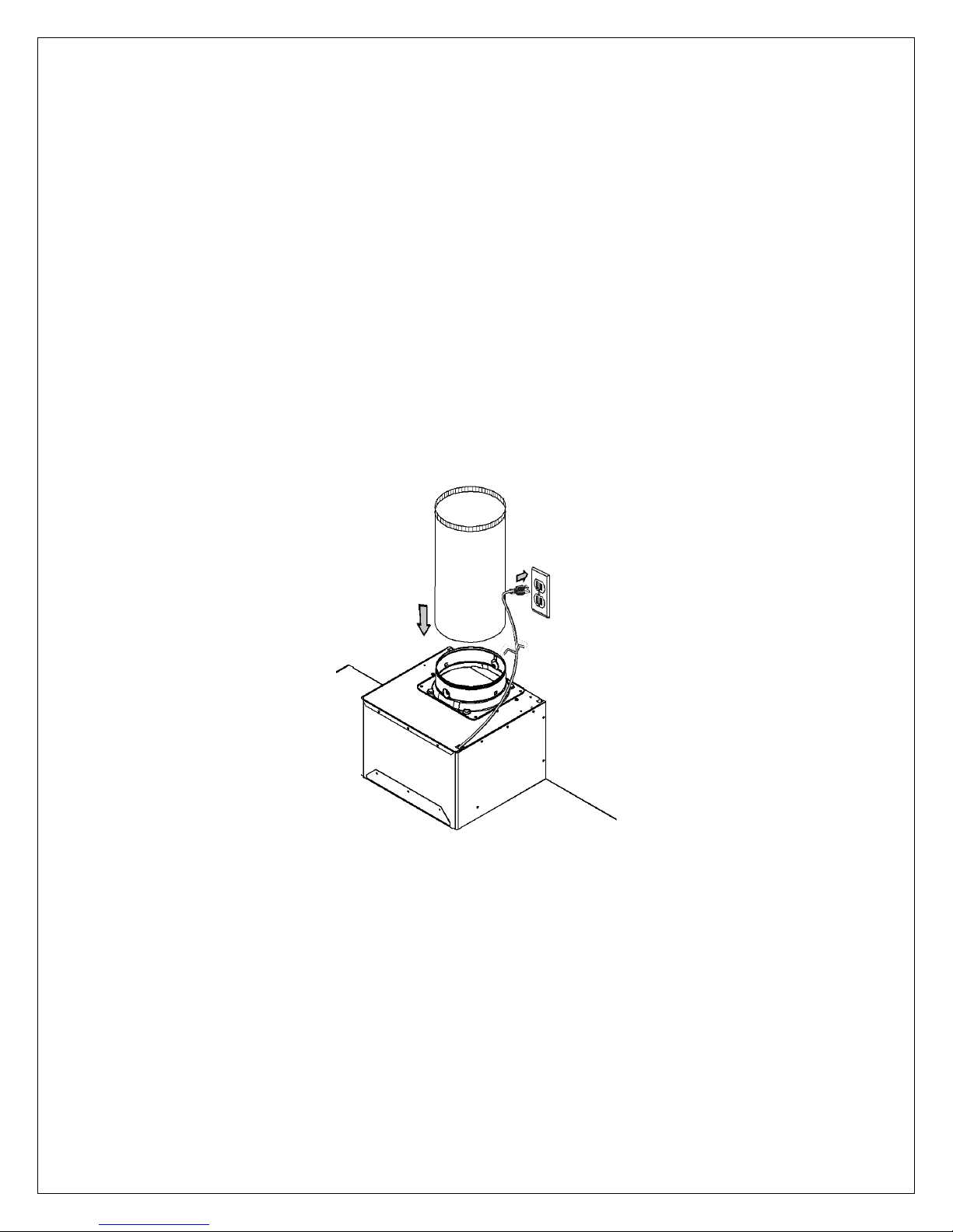
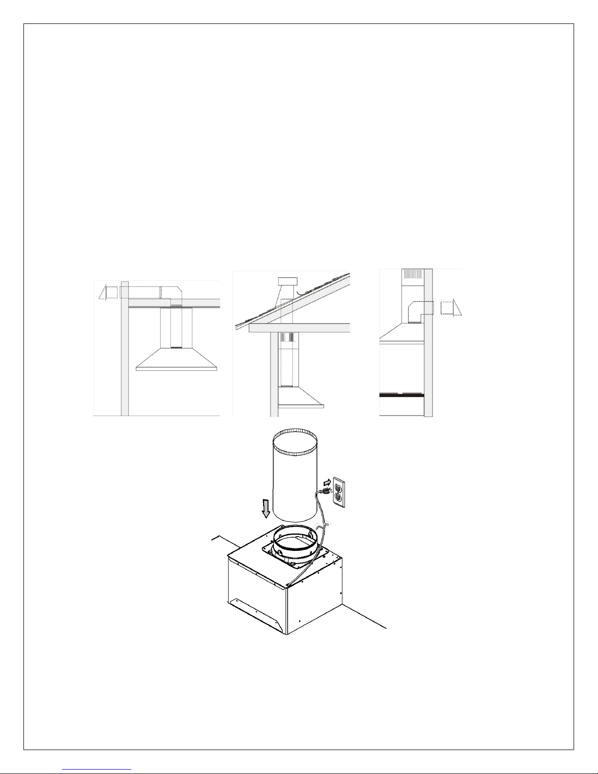
6. Always evacuate outside the conduit system.
To reduce the risk of fire and to properly exhaust air, be sure that the pipe is leading outside, do not exhaust air into the
space between the walls, ceilings, attics, crawl spaces or garages.
WARNING: TO REDUCE THE RISK OF FIRE, USE ONLY METAL DUCT. Install this hood in accordance with all the
requirements mentioned.
WARNING: TO REDUCE THE RISK OF FIRE, GREASE THE RANGE.
1. Never leave the stove unattended when it is at a high temperature. Boil overs cause smoke and fat that overflows can
ignite. Heat the oil slowly at a low or medium temperature.
2. Always operate the hood when you use the stove to high heat or when you
Flambé (Eg. Crepes Suzette, Cherries Jubilee, Peppercorn Beef Flambé).
3. Clean ventilating fans frequently. Do not let fat accumulate on the filters or propellers
4. Use proper pan size. Always use a pot size appropriate to the stove element

WARNING
TO AVOID INJURING SOMEONE IN A GREASE FIRE, FOLLOW THE FOLLOWING:
1. SMOTHER FLAMES with a lid to the dimensions of the cooking hobs, a cookie sheet or other metal tray, then turn
off the gas or power supply of the stove. BE CAREFUL NOT TO BURN YOURSELF. If the flames do not go out
immediately, LEAVE AND CALL THE FIRE DEPARTMENT.
2. NEVER PICK UP A FLAMING PAN, you could hurt yourself.
3. DO NOT USE WATER, including Dish towels or wet towels - a violent steam explosion of dew may occur.
4. Use an extinguisher ONLY if:
. You are sure to have a Class ABC extinguisher that you know how to use.
. The fire is small and confined to the area where it was formed.
. Firefighters were called.
. You can fight against the fire with an exit behind you.
operative MODE
1. Always leave safety grills and filters in place. Without the presence of these, blowers could catch hair, fingers or
clothing. The manufacturer is not liable if detailed in this manual for installation information, maintenance and proper
use of the product are not observed. The manufacturer declines all responsibility for any injury caused by negligence.
In addition, Product Warranty will be voided due to improper maintenance conditions. This product is manufactured
for internal use. Do not use this appliance outdoors.
CAUTION
Automatically controlled device - to reduce the risk of injury, unplug the power supply before repair. The device is
equipped with a switch integration.

5
Electrical requirements and installation requirements
Power Requirements
IMPORTANT
Observe all governing codes and ordinances. The customer is responsible for: Contacting an electrician-installer. Check that the
electrical installation is adequate and in conformance with the National Electrical Code, ANSI / NFPA 70 (latest edition *) or CSA
Standards C22.1-94, Canadian Electrical Code, Part 1 and C22.2 No.0-M91 (the latest edition **) of the CSA, and all codes and
ordinances in your area. If codes permit and use a wire to separate the ground, it is recommended to check the path of the wire
by an electrician. Do not put the device to land on a gas line. Consult a qualified person if you are not sure that the hood is
properly grounded electrically. Do not install a fuse in the neutral circuit or circuit ground.
Location of the electrical installation
• The cable must enter the rear wall at least 20 to 1/4 "above the height of the installation base, and between 7-5/8" and 4-7/8
"from the left side of the midline.
MPORTANT
Keep these instructions in order to return them to the electrical inspector. The hood must be plugged directly into a 110 volt wall
outlet.
Before installing the hood
1. To ensure the most efficient ventilation possible, install the pipe in a straight line or with the least elbows possible.
CAUTION: The output of the vent pipe should give to the outside.
2. Two people are required for installation.
3. Supplied hardware can secure the hood to most walls and ceilings, consult a qualified installer to ensure that the hardware provided is suitable for your type of
wall or cabinet.
4. In the case of areas prone to COLD WEATHER, install a check against extra-circulation to minimize the cold air return and a nonmetallic thermal break to
minimize conduction of outside temperature in the duct. The valve must be placed on the side of the cold air from the heat insulator.
The insulation must be placed as close as possible to where the pipe enters the heated part of the house.
5. Air booster: The building code in your area may require the use of a make-up air system if you use a ventilation system which leads the movement of air
exceeding a certain number of CFM. The number of ft3/min varies from one region to another. Consult your HVAC professional for specific requirements in your
area.
Remove the packaging.
CAUTION
Carefully remove the cardboard, gloves to protect against sharp edges.

Examples and positioning possibilities ducts
Follow the letter of the guidelines presented in this manual.
The manufacturer declines any liability with respect to any loss, damage or fire caused by non-observance of the instructions
contained in this manual.
Ventilation methods
The hood is equipped with a vertical transition to remove fumes outside.
Recommended diameter conduit is 7’’ for model VT-ANG30, VT-ANG36, VT-VIT30, VT-VIT36, VT-ZEN30, VT-ZEN36
Recommended diameter conduit is 6’’ for model VT-ANG650, VT-ZEN650
Models Chimney hood Wall:

7
Chimney hood Wall: VT-BAC30
Positioning options for the hood ducts VT-BAC30
Vertical outlet 6'' round and rectangular horizontal rear exit 4'' 1/2'' x 9'' or 3 1/4 X 10'' provides

Exit 4’’ 1/2 x 9’’ include
Exit 3’’1/4 x 10’’ include

9
Island model Hood : VT-ANG36il, VT-VIT36il, VT-ZEN36il, VT-ZEN3612IL,
VT-ZEN42IL
Positioning options for blocks ducts hoods
VERTICAL DUCT 7'', maximum length pipe is 20’

Under cabinet models: VT-PROC30,VT-PROC36
VERTICAL DUCT 8'' maximum length pipe is 20’
Positioning options for hood ducts under cabinets

11
Under cabinet models : VT-REG30, VT-REG30W,VT-CON30
VERTICAL AND HORIZONTAL RECTANGULAR PIPE 3'' 1/4'' X 10 REQUIRED, otherwise it will create additional
noise. maximum length pipe is 15’

Insert Hood models : VT-IN2816,VT-IN2812
Positioning options for blocks ducts hoods
maximum length pipe is 20’

13
Clearance Training
Do not cut a joist or stud unless it is absolutely necessary to do so. If you need to cut a joist or stud, you must build a support
framework. Supplied hardware can secure the hood to most walls and ceilings. However, you should ask a qualified technician to
check the strength of materials depending on the type of wall or ceiling. Before cutting, make sure there is enough clearance in the
ceiling or wall for the outlet pass. You can determine for yourself how high you install the hood above the stove. Over the hood near
the stove, it is more effective to capture cooking odours, grease and smoke.
CAUTION: INSTALLATION FOR COOKING WITH GAS: INSTALL THE HOOD SO THAT THE DISTANCE BETWEEN THE LOWER EDGE OF
THE HOOD AND THE HOB IS OF 30 "(76.2 CM). FOR ELECTRIC RANGES:. DISTANCE BETWEEN THE BOTTOM EDGE OF THE HOOD
AND COOKING AREA should not be LESS THAN 24 "(61 CM) AND UPPER 30" (76.2 CM). HOUSEHOLD USE. READ THE
INSTRUCTIONS MANUAL FOR SPECIFIC APPLICATIONS.
So check the height of your ceiling and the maximum height of the hood before choosing your range hood.
Clearance

Installation
Installation - Version with duct
• If possible, unplug the stove and move it in order to have better access to the rear wall. Otherwise, place a thick blanket on the counter and
the cooking surface to protect it from damage and dirt. Select a flat surface for assembling the device. Place a protective cover on the surface,
then place the pieces of the canopy hood and hardware.
• Determine and mark the center line on the wall where you installed the canopy hood.
• Determine a comfortable height for the user and mark it on the wall behind the stove top.
• Place the template on the center line and the bottom of the hood with adhesive tape.
Place the squares of the flue
The flue must be installed against the back wall and the ceiling.
This bracket will keep the chimney up to the top.
Attach the brackets to the wall:
• Align the center lines drawn on the bracket with the center lines on the wall.
• Identify the two screw holes on the wall.
• Drill pilot holes 5/16 "in the locations shown.
• Place the fastening clips to the wall.
• Tighten wood screws, by hand, in the attachments to allow hooks to expand. Remove the screws.
• Attach the bracket to the wall using the screws and / or fasteners.
Ceiling pipe
If the duct vents just above the ceiling:
• Use a level to draw a line, the center line of the template to the ceiling.
• Measure at least 4 "from the back wall to the center of the circle with a hole 7 - ½" in the ceiling.
Lead in the wall If the duct vents at the rear:
Note: For a minimum extension of the chimney, we recommend using an adapter circular / rectangular fireplace.
• Use a level to draw a straight line from the center line on the template.
• Measure at least 26 - 1/4 "(the measure may vary elbow used) above the pencil line indicating the height of the bottom of the system, the
circle of a conduit hole 7 - ½ "in diameter (the hole may be enlarged for the passage of the elbow).
Necessary Tools

15
Installation and dimensions diagram, patterns for chimney hood
VT-ANG30, VT-ANG36,VT-ANG650 VT-VIT30, VT-VIT36
VT-ZEN30, VT-ZEN36, VT-ZEN2, VT-ZEN650 VT-BAC30

Installation and dimensions diagram, patterns for hood's chimney

17
Installation and dimensions diagram, patterns for island hoods
VT-ANG36il
VT-VIT36il

Installation and dimensions diagram, patterns for island hoods
VT-ZEN36il, VT-ZEN42
Installation dimensions and patterns for island hoods, ceiling pattern for up to 12
VT-ZEN3612IL

19
Installation and dimensions diagram patterns for island hoods

Installation and dimensions diagram, patterns for hoods: VT-PROC30,VT-PROC36
This manual suits for next models
21
Table of contents