Venini VEF91EG User guide
INSTALLATION, MAINTENANCE AND USE
INSTRUCTIONS FOR
FREE-STANDING COOKERS
90x60 cm (type M9V)
60x60 cm (type M6V)
VEF91EG
VEF61EG
READ THE INSTRUCTION BOOKLET BEFORE INSTALLING AND USING
THE APPLIANCE.
The manufacturer will not be responsible for any damage to property or to persons
caused by incorrect installation or improper use of the appliance.
The manufacturer is not responsible for any inaccuracies, due to printing or transcription
errors, contained in this booklet. In addition, the appearance of the figures reported is also
purely indicative.
The manufacturer reserves the right to make changes to its products when considered
necessary and useful, without affecting the essential safety and operating characteristics.

2
CONTENTS:
THINK APPLIANCES ..................................................................................................................................... 3
INSTALLER TECHNICAL MANUAL ............................................................................................................... 4 - 14
Installing the cooker ........................................................................................................................................ 5 – 6
Room ventilation ............................................................................................................................................. 6
Location and aeration...................................................................................................................................... 6
Appliance gas connection ............................................................................................................................... 7
Adaption to different types of gas.................................................................................................................... 7 – 10
Burner adjustment........................................................................................................................................... 10 – 11
Appliance electric connection.......................................................................................................................... 12 – 13
Important warnings.......................................................................................................................................... 13
Replacing parts............................................................................................................................................... 14
USE AND MAINTENANCE MANUAL ............................................................................................................. 15
Gas burner / hot plate dimensions .................................................................................................................. 15
Control panel description................................................................................................................................. 15
Using burners.................................................................................................................................................. 16 – 17
Use of electric plates....................................................................................................................................... 17 – 18
Using the ceramic hob .................................................................................................................................... 18
Using the gas oven ......................................................................................................................................... 18 – 20
Using the thermostat with switch in series....................................................................................................... 21
Using the electric thermostat........................................................................................................................... 21
Using the oven function knob.......................................................................................................................... 22
Using the natural conventional electric oven................................................................................................... 23
Using the ventilated electric oven.................................................................................................................... 23 – 24
Using the gas grill............................................................................................................................................ 24 – 25
Using the conventional electric grill................................................................................................................. 26
Using the ventilated electric grill...................................................................................................................... 26
Using the minute minder ................................................................................................................................. 26
Analogue clock with timer................................................................................................................................ 27
Electronic timer ............................................................................................................................................... 27 – 28
Cleaning the appliance.................................................................................................................................... 28
After-sales technical service and spare parts.................................................................................................. 29
3
4
THIS APPLIANCE HAS BEEN DESIGNED FOR NON-PROFESSIONAL DOMESTIC USE
INSTALLER TECHNICAL MANUAL
This appliance conforms with the regulations of European directive 2002/95/CE.
This appliance is marked according to the European directive 2002/96/EC on Waste Electrical and
Electronic Equipment (WEEE).
This guideline is the frame of a European-wide validity of return and recycling on Waste Electrical
and Electronic Equipment.
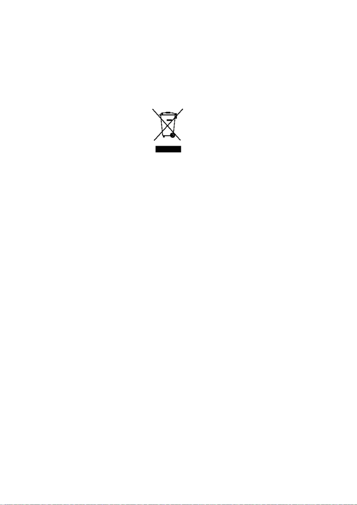
This symbol on the product, or on the documents accompanying the product, indicates that this
appliance may not be treated as household waste. Instead it should be handed over to the applicable
collection point for recycling of electrical and electronic equipment.
Disposal must be carried out in accordance with local environmental regulations for waste disposal.
For more detailed information about treatment, recovery and recycling of this product, please
contact your local city office, your household waste disposal service or the shop where you
purchased the product.
INSTALLER INFORMATION
The installation, all adjustments, transformations and maintenance listed in this part of the manual must be
carried out only by skilled personnel.
Improper installation may cause damage to persons, animals or property, for which the manufacturer will not be
held responsible.
The appliance safety or automatic adjustment devices may be changed during the service life of the system only
by the manufacturer or by the duly authorised supplier.

5
INSTALLING THE COOKER
After having removed the various loose parts from the internal and external packing, make sure that the cooker is not
damaged. If in any doubt, do not use the appliance and contact skilled personnel.
Keep all the dangerous packing parts (polystyrene foam, bags, cardboard, staples, etc.) away from children.
The appliance can be installed as a freestanding unit, next to a wall at a distance of no less than 20mm (Fig.2, Class 1
Installation) or inserted between two walls (Fig.1, Class 2 Subclass 1 Installation). A single sidewall that exceeds the
height of the work surface is possible. This must be at a minimum distance of 70 mm from the edge of the cooker (Fig.2,
Class 1 Installation).
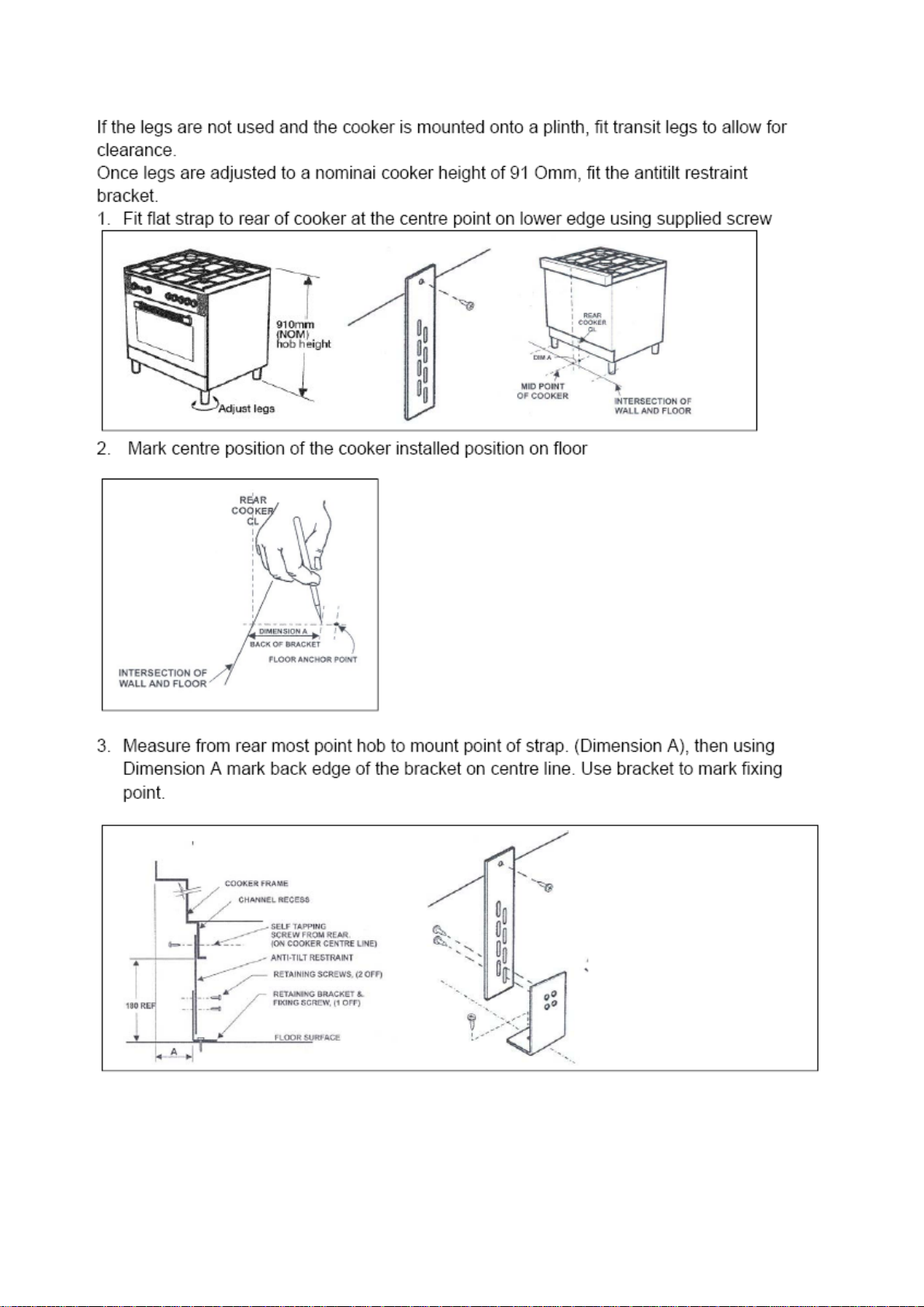
WARNING: In order to prevent accidental tipping of the appliance, for example by a child climbing on to the
oven door, the stabilizing means must be installed according to these instructions
Any walls of the adjacent furniture pieces and the wall behind the cooker must be made of heat-resistant material that
can withstand a minimum temperature of 65°C.
Fig. 1
Fig. 2
6
IMPORTANT INFORMATION FOR INSTALLING THE APPLIANCE
The cooker can be installed separately, as a freestanding unit, or between kitchen units or between a kitchen
unit and the wall. The device must be installed in accordance with the regulations stated in UNI 7129 and UNI
7131 standards.
This appliance is not connected to devices which exhaust combustion products.
Special attention must be focused on the prescriptions described below regarding room aeration and
ventilation. Any hanging cabinets installed above the work surface must be located at a distance of no less than
700 mm.
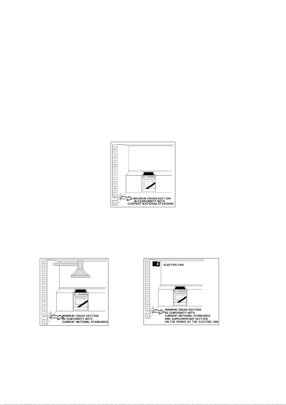
ROOM VENTILATION
To ensure that the appliance operates correctly, the room where it is installed must be continuously ventilated. The room
volume should not be less than 25 m³ and the quantity of air needed should be based on the regular combustion of gas
and on the ventilation of the room. Natural air will flow through permanent openings in the walls of the room to be
ventilated. These openings will be connected with the outside environment and should have a minimum cross-section
defined by the current national standards regarding room ventilation (Fig. 3).
These openings should be built so that they cannot be clogged.
Indirect ventilation is also permitted by taking air from the rooms adjacent to the one to be ventilated.
Fig. 3
LOCATION AND AERATION
Gas cooking appliances must always evacuate the combustion products by means of hoods connected to chimneys,
flues or directly outside (Fig. 4). If a hood cannot be installed, it is possible to use a fan installed on a window or directly
facing outdoors, to be operated together with the appliance (Fig. 5), provided that there is strict compliance with the
ventilation regulations.
Fig. 4 Fig. 5
7
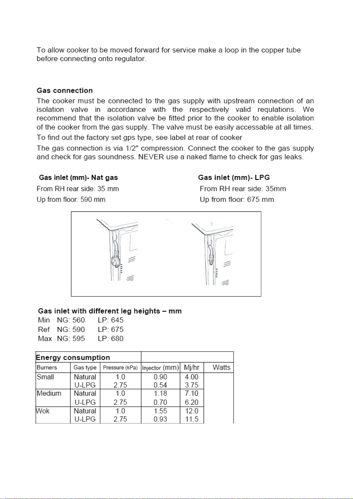
APPLIANCE GAS CONNECTION
Before connecting the appliance to the gas network, make sure that the data on the label attached to the food warmer
drawer or on the back of the cooker are compatible with what is indicated for the gas distribution network.
The label in the food warmer drawer (or on the back) of the appliance indicates the appliance adjustment conditions: type
of gas and operating pressure.
IMPORTANT: This appliance must be installed in compliance with current national standards in force and
used only in a well-ventilated room.
WARNING: The appliance utilises a threaded 1/2" gas cylindrical male fitting according to UNI-ISO 228-1.
To connect the appliance to the gas network with a flexible rubber hose, a supplemental hose nipple fitting is needed
(Fig. 6) which is supplied with the appliance.
8
Table 1

9
10
This manual suits for next models
1
Table of contents
Other Venini Cooker manuals


