Venitem ONDA User manual

EN
MANUALE TECNICO
TECHNICAL MANUAL
ONDA
IT

MANUALE TECNICO / TECHNICAL MANUAL
2
ISTRUZIONI DI SICUREZZA IMPORTANTI
LEGGERE ATTENTAMENTE QUESTA SEZIONE E CONSERVARLA
AVVERTENZA
Rischio di esplosione se la batteria è sostituita con
un tipo errato
Pressione sonora elevata, rischi di danni all’udito

3
DESCRIZIONE
Sirena mod. ONDA L con lampeggiante a led ad alta luminosità e basso assorbimento – tamper antiapertura e
rimozione – programmazione suono e temporizzazione – protezione contro inversione di polarità – autocontrollo
a microprocessore di: batteria e speaker con relativa uscita negativa di anomalia – programmazione di polarità
comando sirena e ON/OFF impianto – segnalazione ottica ON-OFF impianto istantanea e permanente – circuito
elettronico protetto da inversioni di polarità e tropicalizzato in resina contro gli agenti atmosferici e l’umidità –
coperchio esterno, interno e fondo in metallo.
Sirena mod. ONDA LS caratteristiche come ONDA L con sistema antischiuma e antishock a doppio micro contro
gli urti violenti.
Sirena mod. ONDA RGB L caratteristiche come ONDA L con faretto a LED RGBW.
Sirena mod. ONDA RGB LS caratteristiche come ONDA LS con faretto a LED RGBW.
SCHEMA DI COLLEGAMENTO
MORSETTI CONNESSIONI
–1 NEGATIVO ALIMENTAZIONE 0V GND
+2 POSITIVO ALIMENTAZIONE +13,8V
c3 CONTROLLO SIRENA
4 ON/OFF SEGNALAZIONE STATO IMPIANTO
5 INGRESSO RESET FLASH
6USCITA ANOMALIA.
OPEN COLLECTOR, 0V = NESSUNA ANOMALIA
7 AUTO-PROTEZIONE E ANTISCHIUMA N.C.
8 AUTO-PROTEZIONE E ANTISCHIUMA N.C.
AINGRESSO LED ROSSO RGBW (SOLO SU VERSIONE RGB)
BINGRESSO LED VERDE RGBW (SOLO SUVERSIONE RGB)
CINGRESSO LED BLU RGBW (SOLO SU VERSIONE RGB)
DINGRESSO LED ARANCIO RGBW (SOLO SU VERSIONE RGB)
USCITA ANOMALIA
La sirena è gestita da un microprocessore in grado di controllare la presenza della ricarica, la batteria, la tromba; in
caso di anomalia il morsetto 6 open-collector si apre.
Il microprocessore esegue automaticamente ogni 22 ore il test di corrente batteria, segnalato tramite il lampeggio
veloce di LD4 e altri test continuamente. Normalmente, con la sirena alimentata correttamente l’uscita di anomalia
(morsetto 6) rimane a 0V (corrente massima 50mA). In caso di non superamento di qualsiasi test l’uscita di
anomalia si scollega da massa e diventa libera.
Le segnalazioni anomalie si resettano solo con un comando al morsetto 4 o c3. Per avviare il test da remoto della
batteria inviare un impulso al morsetto 5 in questo modo viene avviato il test che dura 30 secondi.
TABELLA DI SEGNALAZIONE E ANOMALIE LED LD4
Interruzione speaker (test ogni 10s) 1 lampeggio
Mancanza corrente di ricarica (V ricarica < 12V) (test ogni 10s) 2 lampeggi
Batteria scollegata (test ogni 10s) 3 lampeggi
Batteria bassa tensione (V ricarica < 10V) (test ogni 10s) 4 lampeggi
Batteria con scarsa capacità, deteriorata (test ogni 22 ore) 5 lampeggi
Nessuna anomalia OFF
Test batteria in corso Veloce
J6 LD4
J2 J3
J1
ON
OFF
SW1
1
1
M1 M2 M3 M4 M5 M6 M7 M8 M9 M10 M11 M12
-1 +2 c3 4 5 6 7 8 A B C D
J5
TAMPER
J4
LED segnalazione
anomalia/test batteria
connettore LED RGBW
J6 LD4
J2 J3
J1
ON
OFF
SW1
1
1
M1 M2 M3 M4 M5 M6 M7 M8 M9 M10 M11 M12
-1 +2 c3 4 5 6 7 8 A B C D
J5
TAMPER
J4
LED segnalazione
anomalia/test batteria
connettore LED RGBW

MANUALE TECNICO / TECHNICAL MANUAL
4
INGRESSO RESET FLASH
Da fabbrica il lampeggiante segue il comando della sirena, per resettare il flash tramite un comando separato
mettere il DIP 6 in OFF.
COLLEGAMENTO TAMPER (ANTIAPERTURA E RIMOZIONE, ANTISCHIUMA E ANTISHOCK)
Collegare ai morsetti n°7 e n°8 la linea tamper proveniente dalla centrale.
DIP-SWITCH
DIP 1 TEMPORIZZAZIONE ALLARME
• Dip-switch 1 in ON DA FABBRICA il tempo di allarme è di 3 minuti.
• Dip-switch 1 in OFF il tempo di allarme è di 8 minuti.
DIP 2 POLARITÀ INGRESSO CONTROLLO SIRENA
N.B.: L’INGRESSO È A MANCARE
• Dip-switch 2 in ON DA FABBRICA il comando per attivare la sirena è positivo.
• Dip-switch 2 in OFF il comando per attivare la sirena è negativo.
DIP 3 SELEZIONE TONI SIRENA
• Dip-switch 3 in ON DA FABBRICA il suono è CRESCENTE-CONTINUO-CALANTE-CONTINUO.
• Dip-switch 3 in OFF il suono è CRESCENTE-CALANTE.
DIP 4 SEGNALAZIONE OTTICA DI STATO IMPIANTO (ON-OFF ISTANTANEO E PERMANENTE) E INGRESSO DI PROVA
DA REMOTO
• Dip-switch 4 in ON DA FABBRICA Situazione istantanea di ON-OFF
• Dip-switch 4 in OFF Situazione istantanea di ON-OFF con permanenza del LED destro intermittente per il tempo
in cui c’è il comando al morsetto n°4.
Portando un comando al morsetto n°4 i LED della sirena eseguono 3 lampeggi (ON) e vengono resettate le
anomalie.
Togliendo il comando i LED rimangono accesi fissi per 5 secondi (OFF).
DIP 5 POLARITÀ INGRESSO SEGNALAZIONE OTTICA DI STATO IMPIANTO / RESET FLASH / COMANDI FARETTO
RGBW
N.B.: GLI INGRESSI SONO A DARE
• Dip-switch 5 in ON DA FABBRICA il comando è negativo.
• Dip-switch 5 in OFF il comando è positivo.
DIP 6 FUNZIONE LAMPEGGIANTE
• Dip-switch 6 in ON DA FABBRICA (Italia) il lampeggiante parte con il comando e si ferma con il comando.
• Dip-switch 6 in OFF DA FABBRICA (Belgio) il lampeggiante parte con il comando e si ferma con il reset (morsetto
n°5).
DIP 7-8 SELEZIONE FUNZIONE FARETTO RGBW (SOLO SU VERSIONE RGB)
• Dip-switch 7-8 in ON-ON DA FABBRICA si attiva il colore del LED in funzione della priorità dei morsetti.
La priorità è: A (alta) - B - C - D (bassa).
• Dip-switch 7-8 in OFF-ON ha la priorità l’ultimo ingresso attivato.
• Dip-switch 7-8 in ON-OFF visualizza a rotazione gli ingressi attivati (nel caso di attivazione di un solo ingresso
il LED è lampeggiante).
• Dip-switch 7-8 in OFF-OFF lampeggio del LED del colore in funzione dell’ordine di arrivo.

5
TAMPER
VITE
TASSELLO (Ø 6 mm)
Fig.1
FORO A
IMPORTANTE: PER EVITARE LA FORMAZIONE
DI CONDENSA NELLA SIRENA SI DEVE
IMPEDIRE QUALSIASI FLUSSO D’ARIA
NELLA CANALINA. PASSARE IL CAVO NEL
DISCHETTO IN NEOPRENE A CELLULE CHIUSE
(FORNITO NEL KIT VITI) INTERPONENDOLO
TRA IL MURO E IL FONDO DELLA SIRENA.
QUESTA OPERAZIONE EVITA CHE DURANTE
IL PERIODO INVERNALE, L’ARIA CALDA E
UMIDA CHE ESCE DALL’EDIFICIO POSSA
ENTRARE NELLA SIRENA E VADA A FORMARE
CONDENSA PRECLUDENDO IL CORRETTO
FUNZIONAMENTO DELLA SIRENA STESSA.
MONTAGGIO
ATTENZIONE: il grado 3 è garantito solo se il disco metallico sottostante al tamper è fissato alla parete come in
fig.1.
1. Appoggiare la sirena al muro e segnare i 4 fori di fissaggio e il foro A (fig.1) per il tamper antirimozione.
2. Praticare i fori sulla parete e inserire i tasselli (non forniti). Per il tamper utilizzare un tasselo di diametro 6 mm
in corrispondenza al foro A
3. Fissare la sirena alla parete controllando che il tamper funzioni correttamente
4. Inserire i cavi di connessione attraverso i fori sul fondo del contenitore
5. Se necessario, modificare le preimpostazioni di fabbrica impostando i DIP Switch come indicato nelle tabelle
6. Collegare la batteria e l’alimentazione alla centrale di allarme
7. Chiudere il coperchio interno con le viti fornite
8. Appoggiare il coperchio esterno verificando che il tamper funzioni correttamente
9. Fissare il coperchio esterno con le viti

MANUALE TECNICO / TECHNICAL MANUAL
6
MADE IN ITALY
GARANZIA
Tutti i prodotti Venitem sono garantiti contro i difetti di fabbricazione o di materiale. Nell’intento di migliorare il design e la qualità dei propri prodotti la
ditta Venitem si riserva di modificare il prodotto senza alcun preavviso. Tutti i prodotti guasti o difettosi vanno resi al proprio fornitore.
Certificato per il Belgio
Conforme alla norma T031
CARATTERISTICHE TECNICHE
Tensione
Nominale di Alimentazione 13,8 Vdc
Comando + c3 minimo 4,5 Vdc
Alimentazione minima 12,7 Vdc
Alimentazione massima 15,5 Vdc
Corrente
Assorbimento suono dalla batteria 0,85 A +100/-300 mA
Max da centrale 700 mA ± 100 mA
Assorbimento lampeggiante 25 mA ± 10 mA
A riposo 15mA
Dagli ingressi di controllo +0,5 mA @Vc=12V; -0,3 mA @Vc=0V
Open collector -50 mA Max
Frequenza fondamentale 2.100 Hz
Potenza acustica massima
J3=ON, collegamento 3 fili
ONDA-LS
LAFmax media su 180° 105 dB(A) @1m
ONDA-RGB-LS
LAFmax media su 180° 107 dB(A) @1m
Potenza acustica minima ONDA-LS e ONDA-RGB-LS [J3=ON/OFF, collegamento 3/2 fili ] LAFmax media su 180° 101 dB(A) @ 1m
Durata lampeggiante LED 1.000.000 lampeggi
Grado di protezione IP 44
Classe ambientale IV (all’esterno)
Condizioni ambientali esterne Da –25° a +55° C
Temporizzazione Programmabile vedi DIP-SWITCH
Comando della centrale 2 o 3 fili
Capacità batteria 12V 2,3Ah
Conforme alla norma INCERT T031:2014
ENTE CERTIFICATORE (IMQ-SISTEMI DI SICUREZZA) EN50131-4:2009
Sicurezza Modelli L, LS, RGB L e RGB LS Grado 3
Dimensioni sirena 226x306x78 (H x L x P)
Peso 2.800 gr.

7
IMPORTANT SAFETY INSTRUCTIONS
READ THE FOLLOWING SECTION CAREFULLY AND STORE IT
WARNING
Explosion risk if the battery is replaced with a
wrong type
High sound pressure, risk of hearing loss

MANUALE TECNICO / TECHNICAL MANUAL
8
DESCRIPTION
Sounder mod. ONDA L with high luminosity and low consumption LED flashing light – anti-opening and anti-
removal tamper protection – anti-foam anti-shock system – programmable sound and timing – protected against
polarity inversion – microprocessor self-test of:
battery and speaker with anomaly negative output - programming of sounder polarity command and system ON/
OFF – immediate or permanent optical indication of ON/OFF system – electronic circuit protected against polarity
inversion and resin tropicalization against bad weather conditions and humidity – external cover, internal cover and
bottom in metal.
Sounder mod. ONDA LS features as per ONDA L with double micro anti-shock anti-foam device against hard hits.
Sounder mod. ONDA RGB L features as per ONDA L with RGBW LED.
Sounder mod. ONDA RGB LS features as per ONDA LS with RGBW LED.
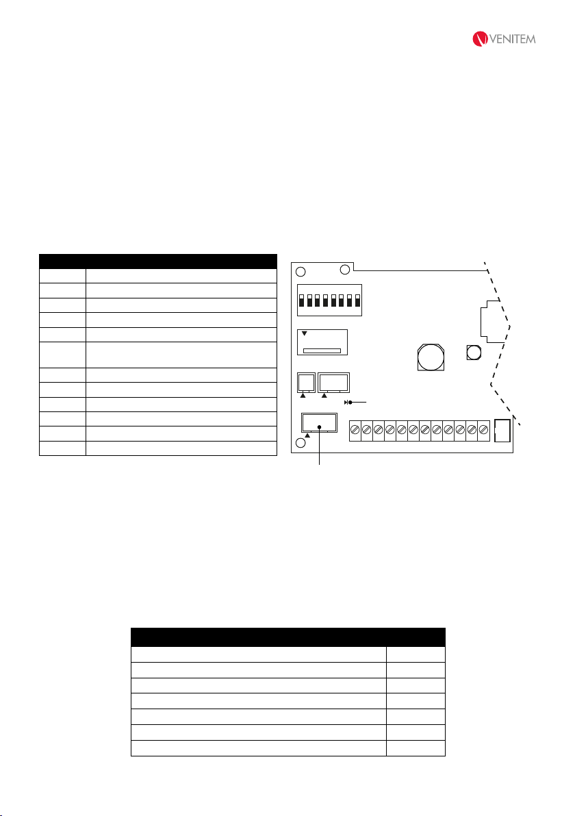
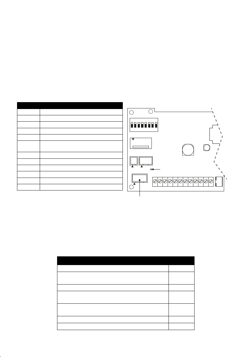
CONNECTION SCHEME
TERMINALS CONNECTIONS
–1 NEGATIVE POWER SUPPLY OV GND
+2 POSITIVE POWER SUPPLY +13.8V
c3 SOUNDER CONTROL
4 ON/OFF - ALARM SYSTEM STATUS NOTICE
5 FLASH RESET INPUT
6ANOMALY OUTPUT. OPEN COLLECTOR
0V = NO ANOMALY
7N.C. SELF-PROTECTION AND ANTI-FOAM
8N.C. SELF-PROTECTION AND ANTI-FOAM
A RED RGBW LED INPUT (ONLY ON RGB VERSION)
B GREEN RGBW LED INPUT (ONLY ON RGB VERSION)
C BLUE RGBW LED INPUT (ONLY ON RGB VERSION)
D WHITE RGBW LED INPUT (ONLY ON RGB VERSION)
ANOMALY OUTPUT
The sounder is managed by a microcontroller able to check battery recharge, battery status and the speaker; in
case of anomaly, open collector terminal (6) opens.
Every 22 hours, the microcontroller automatically performs the battery test, notified by LD4 fast flash and other tests
continuously.
If the sounder is correctly powered, the anomaly output (terminal no. 6) usually stays at 0V (current max 50mA). In
case a test performed is not passed, the anomaly output disconnects from ground and becomes free. Anomalies
notifications are reset to zero only if a command is given to terminal no.4 or c3. To launch the remote battery test, send
a pulse to terminal no. 5. This way, a 30-seconds test runs.
ANOMALY TYPE LD4 LED
Speaker interruption (test performed every 10 s) 1 flash
No recharge current (recharge current is lower than 12V)
(test performerd every 10 s) 2 flashes
Battery is disconnected (test performerd every 10 s) 3 flashes
Battery voltage is low (recharge is lower than 10V)
(test performed every 10 s) 4 flashes
Battery low-capacity, deterioration
(test performed every 22 hours) 5 flashes
No anomalies OFF
Test battery in progress Fast
J6 LD4
J2 J3
J1
ON
OFF
SW1
1
1
M1 M2 M3 M4 M5 M6 M7 M8 M9 M10 M11 M12
-1 +2 c3 4 5 6 7 8 A B C D
J5
TAMPER
LED for anomaly/battery
test signalisation
RGBW LED connector

9
FLASH RESET INPUT
The flashing unit follows the sounder command by default. To reset the flash with a separate command, set DIP 6
in OFF.
TAMPER CONNECTION (ANTI-OPENING AND ANTI-REMOVAL, ANTI-FOAM AND ANTI-SHOCK)
Connect terminals no. 7 and no. 8 to the tamper line coming from the control panel.
DIP-SWITCHES
DIP 1 SOUND TIMING
• Dip-switch 1 in ON: sound timing is 3 minutes (DEFAULT SETTING).
• Dip-switch 1 in OFF: sound timing is 8 minutes.
DIP 2 SOUNDER CONTROL INPUT POLARITY
NOTE: THE INPUT IS MISSING
• Dip-switch 2 in ON: trigger for sounder activation is positive (DEFAULT SETTING).
• Dip-switch 2 in OFF: trigger for sounder activation is negative.
DIP 3 SOUND TYPE SELECTION
• Dip-switch 3 in ON: sound is INCREASING-CONTINUOUS-DECREASING-CONTINUOUS (DEFAULT SETTING).
• Dip-switch 3 in OFF: sound is INCREASING-DECREASING.
DIP 4 SYSTEM STATUS OPTICAL SIGNALISATION (ON-OFF IMMEDIATE AND PERMANENT) AND REMOTE TEST INPUT
• Dip-switch 4 in ON: instantaneous ON-OFF situation (DEFAULT SETTING).
• Dip-switch 4 in OFF: instantaneous ON-OFF situation with right LED flashing intermittently while trigger is given
to terminal 4.
By giving a command to terminal no.4, the LEDs of the sounder blink 3 times (ON) and all anomalies are reset to
zero. By taking command away, the LEDs light up steady for 5 seconds (OFF).
DIP 5 INPUT POLARITY OPTICAL SIGNALISATION OF SYSTEM STATUS / FLASH RESET / RGBW SPOTLIGHT
COMMANDS
NOTE: INPUTS ARE GIVING
• Dip-switch 5 in ON: command is negative (DEFAULT SETTING).
• Dip-switch 5 in OFF: command is positive.
DIP 6 FLASHING UNIT FUNCTION
• Dip-switch 6 in ON: flashing unit starts and stops when the command is given (DEFAULT SETTING)(Italy).
• Dip-switch 6 in OFF: flashing unit starts when the command is given and stops when the reset command is given
(terminal no.5) (DEFAULT SETTING)(Belgium).
DIP 7-8 RGBW FLASHING UNIT FUNCTION SELECTION (ONLY ON RGB VERSION)
• Dip-switch 7-8 in ON-ON: Dip-switches 7-8 in ON-OFF: the LED colour corresponding to terminals priority is
activated (DEFAULT SETTING). Priority is: A (high) – B – C – D (low).
• Dip-switch 7-8 in OFF-on: the last activated input has priority.
• Dip-switch 7-8 in ON-oFF: activated inputs are displayed one by one (in the event of one single activated input,
the LED blinks).
• Dip-switch 7-8 in OFF-oFF: LED flashing colour depending on arrival order.

MANUALE TECNICO / TECHNICAL MANUAL
10
TAMPER
SCREW
PLUG (Ø 6 mm)
PICT.1
A HOLE
MOUNTING
ATTENTION: Degree 3 is guaranteed only if the metal disc under the tamper is fixed to the wall as shown in pict.1.
1. Lay the sounder against the wall and mark the 4 fixing holes and A hole (pic.1) for the anti-removal tamper
2. Drill holes on the wall and insert the plugs (not provided). For the tamper use a 6mm-diameter plug in
correspondance of the A hole
3. Screw the sounder on the wall and check if the tamper works properly
4. Insert the connection cables through the holes located on the sounder base
5. If necessary, modify the default settings acting on the DIP-SWITCHES as indicated in the charts
6. Connect the battery and the power supply to the control panel
7. Close the internal cover using the screws provided
8. Lay the external cover and check if the tamper works properly
9. Fasten the external cover with the screws
IMPORTANTE: TO PREVENT CONDENSATION
FORMATION IN THE SOUNDER, IT IS
IMPORTANT TO AVOID ANY AIR FLOW INSIDE
THE DUCT. TO SUCH PURPOSE, RUN THE
CABLE IN THE CLOSED CELL NEOPRENE DISC
(PROVIDED IN THE SCREW KIT), BY PLACING
IT BETWEEN WALL AND SOUNDER BASE.
THIS OPERATION PREVENTS CONDENSATION
FROM FORMING INSIDE THE SOUNDER;
CONDENSATION MOSTLY APPEARS IN
WINTER AND IT IS USUALLY CAUSED BY
WARM AND HUMID AIR COMING OUT OF THE
WALL WHERE THE SOUNDER IS INSTALLED
AND PASSING THROUGH THE HOLE LOCATED
ON THE SOUNDER BASE.

11
TECHNICAL FEATURES
Voltage
Rated power supply voltage 13.8 Vdc
Minimum command + c34.5 Vdc
Minimum power supply 12.7 Vdc
Maximum power supply 15.5 Vdc
Current
Sound consumption from battery 0,85 A +100/-300 mA
Max from control panel 700 mA ± 100 mA
Flashing unit consumption 25 mA ± 10 mA
Consumption in stand-by 15mA
Consumption from control inputs +0.5 mA @Vc=12V; -0.3 mA @Vc=0V
Open collector -50 mA Max
Fundamental frequency 2,100 Hz
Maximum acoustic power
J3=ON, connection 3 wires
ONDA-LS
LAFmax media on 180° range 105 dB(A) @1m
ONDA-RGB-LS
LAFmax media on 180° range 107 dB(A) @1m
Minimum acoustic power ONDA-LS and ONDA-RGB-LS [J3=ON/OFF, connection 3/2 wires ] LAFmax media on 180° range 101 dB(A) @ 1m
LED flashing unit life 1,000,000 flashes
Protection degree IP 44
Environmental class IV (outdoor)
Working temperature conditions From –25° to +55° C
Timing Settable (see DIP-SWITCHES)
Control panel command 2 or 3 wires
Battery capacity 12V 2.3Ah
Standards compliance INCERT T031:2014
CERTIFYING BODY (IMQ-SISTEMI DI SICUREZZA) EN50131-4:2009
Security Model L, LS, RGB L and RGB LS Degree 3
Size 226x306x78 (H x W x D)
Weight 2,800 gr.
MADE IN ITALY
WARRANTY
All Venitem products are granted against factory or material defects. In order to improve design and quality of the products, Venitem reserves the
right to modify them without prior notice. All faulty or defective items must be returned to the supplier.
Certified for Belgium
Compliant to T031 standards

1542632921
Sede legale e operativa:
Via del Lavoro, 10 30030 Salzano (VE) - Italy
Tel. +39.041.5740374 - Fax +39.041.5740388
UNI EN ISO 14001 UNI EN ISO 9001
AZIENDA CERTIFICATA
MA-SE-ONDA-01-04
Other manuals for ONDA
1
Table of contents
Languages:
Popular Smoke Alarm manuals by other brands

Bentel Security
Bentel Security RF 501t manual

Honeywell
Honeywell FS10-R Installation guide and operating manual

Honeywell
Honeywell JTYJ-GD-01BW manual

Dyna-Glo
Dyna-Glo DGY784BDP-D manual

MasterGuard
MasterGuard 380 Installation and owner's manual

Shandong Renke Control Technology
Shandong Renke Control Technology RS-YG-N01 user manual