manuals.online logo
Brands
  1. Home
  2. •
  3. Brands
  4. •
  5. Gamewell
  6. •
  7. Smoke Alarm
  8. •
  9. Gamewell BD-SS User manual

Gamewell BD-SS User manual

BD-SS and BDT-SS CS-2516 09/01/06 Page 1 of 4
Description
The Gamewell BD-SS and BDT-SS
are intelligent, addressable pro-
jected beam smoke detectors with
SmartScan™ protocol. They are
uniquely suited for protecting open
areas with high and sloping ceilings,
and wide-open areas, where spot-
type smoke detectors are difficult to
install and maintain. Ideal applica-
tions are atriums, cathedral ceil-
ings, aircraft hangers, warehouses,
sporting arenas, concert halls, and
enclosed parking facilities. Installa-
tion of the single-ended reflective
design is much quicker than a dual-
ended projected beam detector.
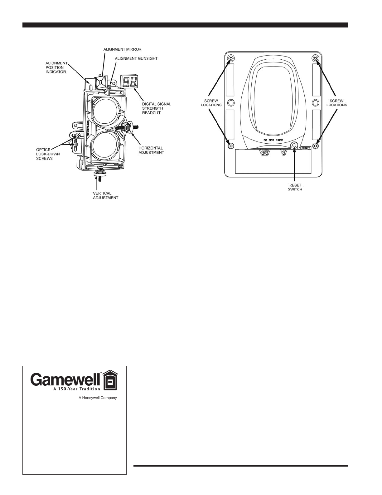
Alignment is easily accomplished
with an optical sight and a two-digit
signal strength meter incorporated
into the beam detector. Listed for operation from –22°F to 131°F, the BD-SS
and BDT-SS are usable in open area applications where temperature
extremes exceed the design limits of other types of smoke detection.
The BD-SS and BDT-SS are a transmitter/receiver unit and a reflector.
When smoke enters the area between the unit and the reflector it causes a
reduction in the signal strength. When the smoke level (signal strength)
reaches the predetermined threshold, an alarm is activated. The detectors
have four standard sensitivity selections as well as two Acclimate™ set-
tings. When either Acclimate™ setting is selected, the detector’s advanced
software algorithms automatically adjust to the optimum sensitivity for the
specific environment. The protection range is 16 to 328 feet and there are
built-in isolators for Style 7 operation.
The BDT-SS has an integral sensitivity test feature of a filter attached to a
servomotor inside the detector optics. Activation of the RTS451 remote test
station moves the filter into the pathway of the light beam, testing the
detector’s sensitivity. This sensitivity test feature allows the user to quickly
and easily meet the annual maintenance and test requirements of NFPA
72, without physical access to the detector.
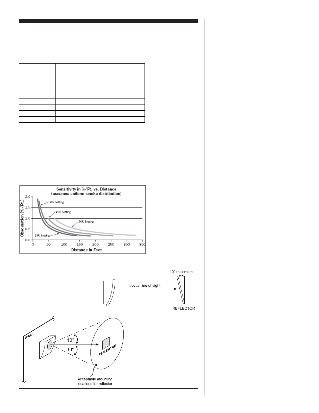
Sensitivity Selection
The detector has six sensitivity selections. Each of these selections is only
acceptable over a specific distance separation between the detector and the
reflector per UL 268. The chart below determines which selections are
acceptable for your installed distance. The sensitivity of the detector can be
set only when the housing is removed and the detector is not in the fine
adjustment step of the alignment mode, indicated by the illumination of the
dual digital display. To set the sensitivity, depress the sensitivity button
one time. See Switch Locations diagram. Once the switch is pressed, the
Features
• Transmitter/receiver built into same unit.
• Six user-selectable sensitivity levels.
• 16' to 328' (use BEAMLRK beyond 230')
protection range.
• Removable plug-in terminal blocks.
• Digital display — no special tools
required.
• Built-in automatic gain control compen-
sates for signal deterioration from dust
buildup.
• Optional remote test station.
• Optional long-range kit (BEAMLRK) for
applications in excess of 230' (70 m).
• Optional multi-mount kit (BEAMMMK)
providing ceiling or wall mount capability
with increased angular adjustment.
• Optional heater kits (BEAMHK and
BEAMHKR) for prevention of condensa-
tion (not intended to increase or reduce
the specified operating temperature).ing
service.
Listings
Listings and approvals below apply to the
basic BD-SS and BDT-SS beam smoke
detectors. In some cases, certain modules
may not be listed by certain approval
agencies, or listing may be in process.
Consult factory for latest listing status.
• UL Listed: file S1195.
• FM approved.
• MEA approved: file 269-04-E.
• CSFM approved: file 7260-1288:171.
BD-SS and BDT-SS
Single-Ended, Reflected-Type, Addressable
Beam Smoke Detector with SmartScan™
BD-SS with reflective plate (top);
and with BEAMMMK
BD-SS and BDT-SS CS-2516 09/01/06Page 2 of 4
digital display will illuminate and read the current sensitivity setting in
percent obscuration. To change the sensitivity, continue to depress the
sensitivity switch until the desired setting is achieved. The digital display
will turn off automatically if no further switch presses occur.
In addition to the four standard sensitivity selections, the detector has two
Acclimate™ settings. When either Acclimate™ setting is chosen, the detec-
tor will automatically adjust its sensitivity using advanced software algo-
rithms to select the optimum sensitivity for the environment. The sensitiv-
ity will be continuously adjusted within the ranges specified in the chart
above.
Total obscuration can be converted to percent per foot, assuming uniform
smoke density for the entire length of the beam. The chart below converts
total obscuration percent per foot for all acceptable sensitivity settings.
Specifications
Operational Specifications
Protection range
16 to 230 feet (5 to 70 m), 230 to 328
feet (70 to 100 m) using optional
BEAMLRK kit.
Adjustment angle
±10° horizontal and vertical. Note that
the optics move independently of the unit.
Sensitivity (6 levels)
• Level 1 — 25%.
• Level 2 — 30%.
• Level 3 — 40%.
• Level 4 — 50%.
• Acclimate™ Level 5 — 30% to 50%.
• Acclimate™ Level 6 — 40% to 50%.
Fault condition (trouble)
• 96% or more obscuration blockage.
• In alignment mode.
• Improper initial alignment.
• Self-compensation limit reached.
Alignment aid
• Optical gunsight.
• Integral signal strength indication.
• Two-digit display.
Indicators
• Alarm — local red LED and remote alarm.
• Trouble — local yellow LED and remote
trouble.
• Normal — local flashing green LED.
Test/reset features
• Integral sensitivity test filter (BDT-SS
only, requires external power supply).
• Sensitivity filter (incremental scale on
reflector).
• Local alarm test switch.
• Local alarm reset switch.
• Remote test and reset switch (compatible
with RTS451 and RTS451KEY test
stations).
Smoke detector spacing
On smooth ceilings, 30 – 60 feet (9.1 to
18.3 m) between projected beams and
not more than one-half that spacing
between a projected beam and a sidewall.
Other spacing may be used depending on
ceiling height, airflow characteristics, and
response requirements. See NFPA 72.
Sensitivity
Setting Percent
Obscuration Display
Reading
Acceptable
DISTANCE
between
detector and
reflector (ft)
Acceptable
DISTANCE
between
detector and
reflector (m
)
Level 1 25% 25 16.4 to 120 5.0 to 36.6
Level 2 30% 30 25 to 150 7.6 to 45.7
Level 3 40% 40 60 to 220 18.3 to 67
Level 4 50% 50 80 to 328 24.4 to 100
Acclimate™ Level 1 30% to 50% A1 80 to 150 24.4 to 45.7
Acclimate™ Level 2 40% to 50% A2 80 to 220 24.4 to 67
6985sens.tbl
Reflector Mounting Guidelines
6985mt2.wmf
6985mt1.wmf
BD-SS and BDT-SS CS-2516 09/01/06 Page 3 of 4
Specifications
Environmental Specifications
Temperature
–22°F to 131°F (–30°C to 55°C).
Humidity
10 – 93% RH noncondensing.
Electrical Specifications
Voltage
15 to 32 VDC.
Average standby current
24 VDC: 2 mA maximum (LED flashing,
SLC @ 24 V).
LED current
6.5 mA maximum.
Remote annunciator current
11.2 mA maximum.
Average current during testing
500 mA maximum.
Alarm current
24 VDC; 8.5 mA maximum (LED on).
Trouble/fault current
24 VDC; 4.5 mA maximum (LED on).
Fault condition current
Add to standby current; 100 mA
maximum.
Alignment mode current
24 VDC; 20 mA maximum.
External supply (BDT-SS only)
Voltage: 15 to 32 VDC.
Current: 0.5 A maximum.
Remote output (alarm)
Voltage: 15 to 32 VDC. NOTE: Output
voltage is the same as device input voltage.
Current: 15 mA maximum, 6 mA
minimum. NOTE: Output current is limited
by 2.2K ohm resistor.
Heater kit BEAMHK
Voltage: 15 to 32 V. Current: 92 mA
maximum @ 32 V (heater only).
Power consumption: nominal 1.6 W
@ 24 V; maximum 3.0 W @ 32 V.
Heater kit BEAMHKR
Voltage: 15 to 32 V. Current: 450 mA
maximum @ 32 V (per reflector). Power
consumption (per reflector): nominal 7.7
W @ 24 V; maximum 15.0 W @ 32 V.
Mechanical Specifications
Detector dimensions
10.0" H x 7.5" W x 3.3" D
(254 mm H x 191 mm W x 84 mm D).
Reflector dimensions
For 16' to 230' (5 to 70 m) applications:
7.9" x 9.1" (200 x 230 mm).
For applications beyond 230'/70 m:
15.7" x 18.1" (400 x 460 mm).
Switch
Locations
Wiring
Diagram
Wiring Diagram (with RTS451/KEY)
g2516w1.wmf
6985swlo.wmf
BD-SS / BDT-SS
BD-SS and BDT-SS CS-2516 09/01/06
Page 4 of 4
Gamewell-FCI
12Clintonville Road
Northford,CT06472-1610
Phone:203-484-7161
Fax:203-484-7118
www.gamewell-fci.com
A Honeywell Company
©2006Gamewell-FCI
Specifications and wiring information are provided for information only and are
believed to be accurate. Gamewell-FCI assumes no responsibility for their use.
Data and design are subject to change without notice. Installation and wiring
instructions shipped with the product shall always be used for actual installation.
For more information, contact Gamewell-FCI.
Alignment Adjustment Locations Housing Screw Locations
Ordering Information
BD-SS Intelligent beam smoke detector
BD-SSA Same as BD-SS with ULC Listing.
BDT-SS Intelligent beam smoke detector with integral
sensitivity test.
BDT-SSA Same as BDT-SS with ULC Listing.
BEAMLRK Long range accessory kit (required for applica-
tions in excess of 230 ft/70 m).
BEAMMMK Multi-mount kit (provides ceiling or wall mount
capability with increased angular adjustment).
BEAMSMK Surface-mount kit.
RTS451 Remote test station.
RTS451KEY Remote test station with key lock.
BEAMHK Heating kit for use with the transmitter/receiver
unit of BDT-SS. For prevention of condensation.
BEAMHRK Heating kit for use with the reflector of BDT-SS.
For prevention of condensation.
Parts List
Item Quantity
Transmitter/receiver unit ....... 1
Paintable trim ring ................. 1
Reflector ................................... 1
Plug-in terminal blocks........... 3
Isolator shunts......................... 2
Instruction manual.................. 1
Orange sticky paper ................ 1
Acclimate™ is a trademark of System Sensor, a Honeywell company.
SmartScan™is a trademark of Gamewell.

This manual suits for next models

1

Other Gamewell Smoke Alarm manuals

Gamewell Velociti Series User manual

Gamewell

Gamewell Velociti Series User manual

Gamewell 7100 series User manual

Gamewell

Gamewell 7100 series User manual

Gamewell IF600 User manual

Gamewell

Gamewell IF600 User manual

Gamewell MS-7AF User manual

Gamewell

Gamewell MS-7AF User manual

Popular Smoke Alarm manuals by other brands

Airam ALE! operating instructions

Airam

Airam ALE! operating instructions

Fire-Lite CP355 Installation and maintenance instructions

Fire-Lite

Fire-Lite CP355 Installation and maintenance instructions

WindowMaster WSC 308 01 Operation manual / technical information

WindowMaster

WindowMaster WSC 308 01 Operation manual / technical information

Fire-Lite AFM-16ATX user manual

Fire-Lite

Fire-Lite AFM-16ATX user manual

Abus FU8340 Instruction

Abus

Abus FU8340 Instruction

Abus GRWM30500 user manual

Abus

Abus GRWM30500 user manual

LST ÜMM-55000-833 Specification sheet

LST

LST ÜMM-55000-833 Specification sheet

Fenwal F1H-Q-RYW1K Operation & instruction manual

Fenwal

Fenwal F1H-Q-RYW1K Operation & instruction manual

Tunstall 67005/94 User & installation instructions

Tunstall

Tunstall 67005/94 User & installation instructions

BRK electronic 9120LBLA Specification sheet

BRK electronic

BRK electronic 9120LBLA Specification sheet

Fire-Lite Alarms D350P Installation and maintenance instructions

Fire-Lite Alarms

Fire-Lite Alarms D350P Installation and maintenance instructions

MGC SD-100 Series Installation and maintenance instructions

MGC

MGC SD-100 Series Installation and maintenance instructions

First Alert 7020b user manual

First Alert

First Alert 7020b user manual

Bosch FAP-520 installation manual

Bosch

Bosch FAP-520 installation manual

ZyXEL Communications SHD1115 manual

ZyXEL Communications

ZyXEL Communications SHD1115 manual

Mini Gadgets BB4KWiFiUltraSmoke user manual

Mini Gadgets

Mini Gadgets BB4KWiFiUltraSmoke user manual

Polon-Alfa POLON 4000 Series Operation and maintenance

Polon-Alfa

Polon-Alfa POLON 4000 Series Operation and maintenance

Tyco IR6003/7 Product user guide

Tyco

Tyco IR6003/7 Product user guide

manuals.online logo
manuals.online logoBrands
  • About & Mission
  • Contact us
  • Privacy Policy
  • Terms and Conditions

Copyright 2025 Manuals.Online. All Rights Reserved.