Venmar ERV5000-10000 Manual

©2008 Venmar CES Inc.
Aston-built Products
Custom-built Dedicated Outdoor Air Systems
Installation, Operation and Maintenance Instructions Manual
Capacities: 1,000 to 300,000+ cfm
Model: EnergyPack®, ERV5000–10000 (indoor/
outdoor), HRV3000–10000 (indoor/outdoor)

Table of Contents
Nomenclature ......................................................................................................................................................................3
Safety Considerations .........................................................................................................................................................8
General Information ...........................................................................................................................................................8
Recommended Spare Parts ...........................................................................................................................................8
Unit Inspection on Arrival.............................................................................................................................................9
Unit Application Limitations ........................................................................................................................................9
Installation ...........................................................................................................................................................................9
Unit Location Requirements .........................................................................................................................................9
Roofcurbs Supplied by Venmar CES (External Applications Only) ...........................................................................10
Roofcurbs Supplied by Others ....................................................................................................................................10
Rigging, Lifting and Assembling ................................................................................................................................11
Hood Installation.........................................................................................................................................................17
Indoor Suspended Installation ...................................................................................................................................17
Field Fabricated Ductwork..........................................................................................................................................18
Electrical Connections .................................................................................................................................................19
Coil, WSHP or Humidifier Piping Connections ..........................................................................................................20
Condensate Drain Trap and Lines ..............................................................................................................................21
Gas Connections ..........................................................................................................................................................21
Refrigerant Systems ....................................................................................................................................................21
Start-up ..............................................................................................................................................................................21
Pre Start-up Check.......................................................................................................................................................21
Start-up Procedure ......................................................................................................................................................23
Airflow Balancing........................................................................................................................................................24
Maintenance ......................................................................................................................................................................25
Long-term Storage Maintenance Procedures ............................................................................................................25
Maintenance Summary Chart .....................................................................................................................................25
Energy Recovery Wheel ..............................................................................................................................................25
Flat Plate Heat/Enthalpy Exchangers .........................................................................................................................29
Heat Pipe Heat Exchangers.........................................................................................................................................29
Refrigerant Systems ....................................................................................................................................................30
Dampers .......................................................................................................................................................................31
Belt Driven Fans...........................................................................................................................................................32
FANWALL® Array .........................................................................................................................................................34
Motors..........................................................................................................................................................................39
Filters............................................................................................................................................................................39
Coils ..............................................................................................................................................................................39
Controls........................................................................................................................................................................40
Troubleshooting ..........................................................................................................................................................40
Appendix A: Roofcurb Generic Assembly Instructions ....................................................................................................41
Appendix B: Water Source Heat Pump (WSHP) Piping, Installation, Maintenance and Troubleshooting ..................42
Appendix C: Positive and Negative Pressure Trapping ...................................................................................................47
Appendix D: Gas-fired Furnace Modules Installation and Maintenance .......................................................................48
Tubular Gas-fired Duct Furnace Module ...................................................................................................................48
IG Series Drum and Tube Gas-fired Duct Furnace Module .......................................................................................62
Appendix E: EnergyPack®, ERV5000–10000(i/e) and HRV3000–10000(i/e) Start-up Form and Checklist .....................82
Appendix F: HEPA Filter Installation ................................................................................................................................90
Appendix G: Electric Heating Coil and Controls Information ........................................................................................92
Appendix H: Extended Dormant Unit Maintenance Procedure .....................................................................................94
Appendix I: EnergyPack®, ERV5000–10000 and HRV3000–10000 Maintenance Summary Chart .................................97
Appendix J: Measuring and Adjusting V-belt Tension ...................................................................................................98
Appendix K: Energy Recovery Wheel Multi-link Drive Belt Instructions .......................................................................99
Appendix L: Fan Bearing Lubrication Schedule .............................................................................................................100
Appendix M: FANWALL® Inlet Cone Alignment ...........................................................................................................101
Appendix N: Filter Resistance and Latches ....................................................................................................................102
Appendix O: Troubleshooting ........................................................................................................................................103
Appendix P: Adjusting Refrigerant Charge ...................................................................................................................105
Manufacturer reserves the right to discontinue or change specifications or designs without notice or obligation.
VCES-ASTON-IOM-1D – EnergyPack, ERV5000–10000, HRV3000–10000 2

Nomenclature
©Venmar CES Inc. 2008. All rights reserved throughout the world.
Illustrations cover the general appearance of Venmar CES products at the time of publication and Venmar CES reserves the
right to make changes in design and construction at any time without notice.
™® The following are trademarks or registered trademarks of their respective companies: EnergyPack from Venmar CES Inc.
and FANWALL from Huntair, Inc.
CES Group, LLC d/b/a Venmar CES furnishes equipment pursuant to its then-current Terms and Conditions of Sale and Lim-
ited Warranty, copies of which can be found under the Terms & Conditions of Sale and Warranty link at www.ces-group.com.
Extended warranties, if any, shall be as offered and acknowledged in writing by Venmar CES.
1. TYPE OF HE
AT OR ENERGY RECOVERY DEVICE
W – Wheel - total enthalpy
Ws – Wheel - sensible only
P – Plate - sensible only
(polypropylene or aluminum)
Pe – Plate - enthalpy (HM core)
Pa – Plate - AlphaFlowSM configuration, sensible only
H – Heat pipe heat exchanger
U – U-shaped heat pipe
A – No energy recovery device
(make-up or air handling units)
8. TYPE OF HEATING/COOLING
HWCW – Hydronic coil for hot water in heating
season and chilled water in cooling season
HPxxxy – Dx coil with heat pump
(xxx = cooling capacity;
y = # of scroll compressors)
RL – Runaround loop
X – No heating/cooling
9. EXTERIOR FINISH
P – Painted finish (standard for exterior units)
C – Corrosion resistant paint
G – Galvanized metal - unpainted
(standard for interior units)
2. NUMBER OF AIRSTREAMS
3. SUPP
LY CFM
Rounded to the nearest thousand
4. INDICA
TES UNIT INSTALLATION
e – Unit installed outdoors
i – Unit installed indoors
5. TYPE OF SUPPL
Y FAN/
TYPE OF EXHAUST
FAN
F – DWDI forward curved fan
B – DWDI backward inclined, or flat blade
P – SWSI plenum fan (backward inclined airfoil)
W – FANWALL TECHNOLOGY®
P – No fan
6. TYPE OF HEA
TING
HW – Hot water coil
SC – Steam coil
yTxxxx – Gas-fired serpentine heaters
(y = # of furnace sections; xxxx = heating capacity)
yRxxxx – Indirect gas-fired duct heaters
(y = # of furnace sections; xxxx = heating capacity)
ECxxx – Electric duct heater (xxx = heating capacity)
HG – Hot gas reheat coil (condensing unit supplied by others)
HGxxxx
– Hot gas reheat coil (condensing unit supplied by Venmar CES;
xxxx = heating capacity)
IGxxxx – Indirect gas-fired heaters (xxxx = input heating capacity)
DGxxxx
– Direct fired gas burner (xxxx = input heating capacity)
X – No heating
7. TYPE OF COOLING
CW – Chilled water coil
Dx – Dx coil (condensing unit supplied
by others)
CSxxxy – Dx coil with air cooled condensing unit
(xxx = cooling capacity;
y = # of scroll compressors)
CTxxxy – Dx coil with air cooled condensing unit
(xxx = cooling capacity;
y = # of scroll compressors in tandem)
Cxxxy – Dx coil with air cooled condensing unit
(xxx = cooling capacity;
y = # of semi-hermetic compressors)
EV – Evaporative cooling section
X – No cooling
12 3 4 5 6 7 8 9
EnergyPack
®Nomenclature (1,000–300,000+ cfm)
VCES-ASTON-IOM-1D – EnergyPack, ERV5000–10000, HRV3000–10000 3

1. FROST CONTROL
D
– Recirc defrost1
E
– Exhaust only2
V
– VSD frost prevention
N
– Non-defrost3
3. SENSOR CONT
ACTS
D
– Dirty filter contacts
W
– Wheel rotation sensor
B
– Dirty filter contacts and
wheel rotation sensor
X
– No contacts, no sensor
9. EXHAUST DISCHARGE
E
– End exhaust discharge
T
– Top exhaust discharge
D
– Down exhaust discharge
4. EXTERNAL FINISH
S
– Standard galvanized package
G
– Grey enamel paint finish
C
– Corrosion resistant exterior paint finish
7. EXTERNAL DISCONNECT
F
– Fused disconnect switch7
N
– Non-fused disconnect switch7
X
– No disconnect switch
8. OUTSIDE AIR INT
AKE
E
– End outside air intake
T
– Top outside air intake
S
– Side outside air intake
B
– Bottom outside air intake
5. OUTSIDE AIR DAMPE
R
1
– Non-insulated spring return (low leak)
2
– Insulated spring return (low leak)
3
– No damper
6. EXHAUST AIR DAMPER
1
– Non-insulated spring return (low leak)
2
– Insulated spring return (low leak)
3
– No damper
2. VO
LTAGE/SPEED
B
– 208 VAC/1/60 – one-speed8/10*
C
– 230 VAC/1/60 – one-speed8/10*
D
– 208 VAC/3/60 – one-speed
E
– 230 VAC/3/60 – one-speed
F
– 460 VAC/3/60 – one-speed
G
– 575 VAC/3/60 – one-speed
N
– 208 VAC/3/60 – VFD4
O – 230 V
AC/3/60 – VFD4
P
– 460 VAC/3/60 – VFD4
Q – 575 V
AC/3/60 – VFD4/5
13. HEF FILTRATION
H – High efficiency supply filter
(4” 80–85% MERV 14)6
X – No HEF filtration
14. FREE COOLING
E – Free cooling (enthalpy controller)
D – Free cooling (dry bulb)
X – No free cooling
15. BLOWER ISOLATION
R – Rubber in shear pads isolation
S – Spring blower isolation
16. PURGE SECTION
P – Purge section
X – No purge section
18. COOLING
C – Chilled water (5 row)
W– Chilled water (6 row)
D – Dx cooling (5 row, 1 circuit)
F – Dx cooling (6 row, 2 circuits)
X – No cooling
19. COIL ARRANGEMENT
H – Heating, cooling, access section
C – Cooling, heating, access section
S – Heating, cooling, no access section
X – No access section
(one coil or no coils)
10. SUPP
LY DISCHARGE
E
– End supply discharge
T
– Top supply discharge
D
– Down supply discharge 12. MEF FILTRATION
S – MEF supply filter6
E – MEF exhaust filter
B – MEF supply and exhaust filters
X – No MEF filtration
11. RETURN AI
R
E
– End return air
T
– Top return air
B
– Bottom return air
17. HEATING
ERV5000i–10000i
H – Hot water (1 row)
J – Hot water (2 row)
S – Steam heat (1 row)
G – Hot gas re-heat (2 row)
X – No heat
ERV5000i
D – Electric heat (25 kW)8/9
E – Electric heat (43 kW)8/9
F – Electric heat (78 kW)8/9
ERV6500i
D – Electric heat (35 kW)8/9
E – Electric heat (55 kW)8/9
F – Electric heat (100 kW)8/9
ERV8000i
D – Electric heat (42 kW)8/9
E – Electric heat (71 kW)8/9
F – Electric heat (128 kW)8/9
ERV10000i
D – Electric heat (54 kW)8/9
E – Electric heat (91 kW)8/9
F – Electric heat (164 kW)8/9
Note:
1
When ordering frost control, you must order outside air and exhaust air dampers. VFD motors are not available with this frost control option.
2
Outside air damper recommended. VFD motors are not available with this frost control option.
3
No dampers required.
4
All VFD options include one controller per motor.
5
All VFD options for 575 VAC/3/60 include a line reactor.
6
You must order an MEF supply filter when ordering HEF supply filtration.
7
Fused/non-fused disconnect is factory installed.
8
Electric heat is not available with single-phase motor options.
9
Electric heat to be used in re-heat position only (not for frost control).
10 15 hp motor is not available with this voltage option (*ERV10000i only).
5 96 7 81 2 3 4 10 13 14 15 16 17 18 1911 12
ERV5000–ERV10000 Indoor Nomenclature (4,000–10,000)
VCES-ASTON-IOM-1D – EnergyPack, ERV5000–10000, HRV3000–10000 4

1. FROST CONTROL
D
– Recirc defrost1
E
– Exhaust only2
V
– VSD frost prevention
N
– Non-defrost3
3. SENSOR CONT
ACTS
D
– Dirty filter contacts
W
– Wheel rotation sensor
B
– Dirty filter contacts and
wheel rotation sensor
X
– No contacts, no sensor
9. SUPP
LY DISCHARGE
D
– Down supply discharge
E
– End supply discharge
4. EXTERNAL FINISH
S
– Standard galvanized package
G
– Grey enamel paint finish
C
– Corrosion resistant exterior paint finish
7. EXTERNAL DISCONNECT
F
– Fused disconnect switch8
N
– Non-fused disconnect switch8
X
– No disconnect switch
8. HOODS
H
– Intake/exhaust hoods
X
– No hoods4
5. OUTSIDE AIR DAMPE
R
1
– Non-insulated spring return (low leak)
2
– Insulated spring return (low leak)
3
– No damper
6. EXHAUST AIR DAMPER
1
– Non-insulated spring return (low leak)
2
– Insulated spring return (low leak)
3
– Gravity backdraft damper (low leak)
4
– No damper
2. VO
LTAGE/SPEED
B
– 208 VAC/1/60 – one-speed9/11*
C
– 230 VAC/1/60 – one-speed9/11*
D
– 208 VAC/3/60 – one-speed
E
– 230 VAC/3/60 – one-speed
F
– 460 VAC/3/60 – one-speed
G
– 575 VAC/3/60 – one-speed
N
– 208 VAC/3/60 – VFD5
O – 230 V
AC/3/60 – VFD5
P
– 460 VAC/3/60 – VFD5
Q – 575 V
AC/3/60 – VFD5/6
13. FREE COOLING
E – Free cooling (enthalpy controller)
D – Free cooling (dry bulb)
X – No free cooling
14. BLOWER ISOLATION
R – Rubber in shear pads isolation
S – Spring blower isolation
15. PURGE SECTION
P – Purge section
X – No purge section
17. COOLING
C – Chilled water (5 row)
W– Chilled water (6 row)
D – Dx cooling (5 row, 1 circuit)
F – Dx cooling (6 row, 2 circuits)
X – No cooling
18. COIL ARRANGEMENT
H – Heating, cooling, access section
C – Cooling, heating, access section
S
– Heating, cooling, no access section
X – No access section
(one coil or no coils)
10. RETURN AI
R
B
– Bottom return air
E
– End return air
19. ROOFCURB
R – Insulated roofcurb
X – No roofcurb
12. HEF FILTRATION
H – High efficiency supply filter
(4” 80–85% MERV 14)7
X – No HEF filtration
11. MEF FIL
TRATION
S
– MEF supply filter7
E
– MEF exhaust filter
B
– MEF supply and exhaust filters
X
– No MEF filtration
16. HEATING
ERV5000e–10000e
H – Hot water (1 row)
J – Hot water (2 row)
S – Steam heat (1 row)
G – Hot gas re-heat (2 row)
X – No heat
ERV5000e
D – Electric heat (25 kW)9/10
E – Electric heat (43 kW)9/10
F – Electric heat (78 kW)9/10
ERV6500e
D – Electric heat (35 kW)9/10
E – Electric heat (55 kW)9/10
F – Electric heat (100 kW)9/10
ERV8000e
D – Electric heat (42 kW)9/10
E – Electric heat (71 kW)9/10
F – Electric heat (128 kW)9/10
ERV10000e
D – Electric heat (54 kW)9/10
E – Electric heat (91 kW)9/10
F – Electric heat (164 kW)9/10
Note:
1
When ordering frost control, you must order outside air and exhaust air dampers. VFD motors are not available with this frost control option.
2
Outside air damper recommended. VFD motors are not available with this frost control option.
3
No dampers required.
4
Must order hoods when ordering dampers.
5
All VFD options include one controller per motor.
6
All VFD options for 575 VAC/3/60 include a line reactor.
7
You must order an MEF supply filter when ordering HEF supply filtration.
8
Fused/non-fused disconnect is factory installed.
9
Electric heat is not available with single-phase motor options.
10
Electric heat to be used in reheat position only (not for frost control).
11 15 hp motor is not available with the voltage option (*ERV10000e only).
5 96 7 81 2 3 4 10 13 14 15 16 17 18 1911 12
ERV5000–ERV10000 Outdoor Nomenclature (4,000–10,000)
VCES-ASTON-IOM-1D – EnergyPack, ERV5000–10000, HRV3000–10000 5

1. FROST CONTROL
D
– Recirc defrost1/4
E
– Exhaust only2/4
F
– Face and bypass3
T
– Traversing defrost4
N
– Non-defrost5
3. ENERGY RECOVER
Y
P
– Poly core10
A
– Aluminum core
H
– HM core11
9. EXTERNAL DISCONNECT
F
– Fused disconnect switch15
N
– Non-fused disconnect switch15
X
– No disconnect switch
4. INTERNAL PROTECTION
1
– 2” insulation, double wall
2
– Corrosion resistant interior (heresite)
3
– Pool application package12/13/14
7. OUTSIDE AIR DAMPER
1
– Non-insulated spring return (low leak)
2
– Insulated spring return (low leak)
3
– No damper
8. EXHAUST AIR DAMPER
1
– Non-insulated spring return (low leak)
2
– Insulated spring return (low leak)
3
– No damper
5. SENSOR CONT
ACTS
D
– Dirty filter contacts
X
– No contacts
6. EXTERNAL FINISH
S
– Standard galvanized package
G
– Grey enamel paint finish
C
– Corrosion resistant exterior
2. VO
LTAGE/SPEED
B
– 208 VAC/1/60 – one-speed6/7*
C
– 230 VAC/1/60 – one-speed6/7*
D
– 208 VAC/3/60 – one-speed
E
– 230 VAC/3/60 – one-speed
F
– 460 VAC/3/60 – one-speed
G
– 575 VAC/3/60 – one-speed
N
– 208 VAC/3/60 – VFD8
O – 230 V
AC/3/60 – VFD8
P
– 460 VAC/3/60 – VFD8
Q – 575 V
AC/3/60 – VFD8/9
14. FILTRATION
S – Standard filtration
(2” 25–30% MERV 8)
H – High efficiency filtration
(4” 80–85% MERV 14)
15. BLOWER ISOLATION
R – Rubber in shear pads isolation
S – Spring blower isolation
17. COOLING
C – Chilled water (5 row)
W– Chilled water (6 row)
D – Dx cooling (5 row, 1 circuit)
F – Dx cooling (6 row, 2 circuits)
X – No cooling
18. COIL ARRANGEMENT
H – Heating, cooling, access section
C – Cooling, heating, access section
S – Heating, cooling, no access section
X – No access section (one coil or no coils)
10. OUTSIDE AIR INT
AKE
E
– End outside air intake
T
– Top outside air intake 13. RETURN AIR
E – End return air
B – Bottom return air
12. SUPPLY DISCHARGE
E – End supply discharge
D – Down supply discharge
11. EXHAUST DISCHARGE
E
– End exhaust discharge
T
– Top exhaust discharge
16. HEATING
HRV3000i–10000i
H – Hot water (1 row)
S – Steam heat (1 row)
J – Hot water (2 row)
X – No heat
HRV3000i
D – Electric heat (15 kW)6/16
E – Electric heat (27 kW)6/16
F – Electric heat (49 kW)6/16
HRV5000i
D – Electric heat (25 kW)6/16
E – Electric heat (43 kW)6/16
F – Electric heat (78 kW)6/16
HRV6500i
D – Electric heat (35 kW)6/16
E – Electric heat (55 kW)6/16
F – Electric heat (100 kW)6/16
HRV8000i
D – Electric heat (42 kW)6/16
E – Electric heat (71 kW)6/16
F – Electric heat (128 kW)6/16
HRV10000i
D – Electric heat (54 kW)6/16
E – Electric heat (91 kW)6/16
F – Electric heat (164 kW)6/16
Note:
1
When ordering frost control, you must order outside air and exhaust
air dampers.
2
Outside air damper recommended.
3
And/or free cooling (c/w dampers and actuator).
4
VFD motors are not available with this frost control option.
5
No dampers required. Non-defrost is only available if the outside air
temperature is greater than 10ºF [−17ºC].
6
Electric heat is not available with single-phase motor options.
7
15 hp motor is not available with this voltage option. (*HRV10000i only)
8
All VFD options include one controller per motor.
9
This option includes a line reactor.
10
Traversing defrost may not be suitable under all thermal conditions with a
polypropylene heat exchanger. Consult the factory.
11 Traversing defrost is not available with the HM core option.
12 The ‘Pool application package’ requires the following nomenclature options
also be selected: ‘F – Face and bypass’ (Frost Control), ‘P – Poly core’ (Energy
Recovery), ‘2 – Insulated spring return (low leak)’ (Outside Air Damper) and
‘2 – Insulated spring return (low leak)’ (Exhaust Air Damper).
13 The ‘Pool application package’ includes: corrosion resistant (heresite) internal
unit protection, epoxy coating on the exhaust air fan, TEFC exhaust air fan
motor, liquid tight conduit on all high voltage wiring, urethane insulation
throughout (including insulated middle partition), condensate drain pan at
exhaust air leaving station.
14 It is recommended that supply and return dampers be installed in the ductwork.
These dampers shall close when the unit is not in operation.
15 Fused/non-fused disconnect switch is factory installed.
16 Electric heat to be used in re-heat position only (not for frost control).
5 96 7 81 2 3 4 16 17 1810 11 12 13 14 15
HRV3000–HRV10000 Indoor Nomenclature (2,500–11,500 cfm)
VCES-ASTON-IOM-1D – EnergyPack, ERV5000–10000, HRV3000–10000 6

1. FROST CONTROL
D
– Recirc defrost1/4
E
– Exhaust only2/4
F
– Face and bypass3
T
– Traversing defrost4
N
– Non-defrost5
3. ENERGY RECOVER
Y
P
– Poly core10
A
– Aluminum core
H
– HM core11
9. EXTERNAL DISCONNECT
F
– Fused disconnect switch15
N
– Non-fused disconnect switch15
X
– No disconnect switch
4. INTERNAL PROTECTION
1
– 2” insulation, double wall
2
– Corrosion resistant interior (heresite)
3
– Pool application package12/13/14
7. OUTSIDE AIR DAMPE
R
1
– Non-insulated spring return (low leak)
2
– Insulated spring return (low leak)
3
– No damper
8. EXHAUST AIR DAMPER
1
– Non-insulated spring return (low leak)
2
– Insulated spring return (low leak)
3
– No damper
5. SENSOR CONT
ACTS
D
– Dirty filter contacts
X
– No contacts
6. EXTERNAL FINISH
S
– Standard galvanized package
G
– Grey enamel paint finish
C
– Corrosion resistant exterior
2. VO
LTAGE/SPEED
B
– 208 VAC/1/60 – one-speed6/7*
C
– 230 VAC/1/60 – one-speed6/7*
D
– 208 VAC/3/60 – one-speed
E
– 230 VAC/3/60 – one-speed
F
– 460 VAC/3/60 – one-speed
G
– 575 VAC/3/60 – one-speed
N
– 208 VAC/3/60 – VFD8
O – 230 V
AC/3/60 – VFD8
P
– 460 VAC/3/60 – VFD8
Q – 575 V
AC/3/60 – VFD8/9
13. FILTRATION
S – Standard filtration
(2” 25–30% MERV 8)
H – High efficiency filtration
(4” 80–85% MERV 14)
14. BLOWER ISOLATION
R – Rubber in shear pads isolation
S – Spring blower isolation
16. COOLING
C – Chilled water (5 row)
W– Chilled water (6 row)
D – Dx cooling (5 row, 1 circuit)
F – Dx cooling (6 row, 2 circuits)
X - No cooling
17. COIL ARRANGEMENT
H – Heating, cooling, access section
C – Cooling, heating, access section
S – Heating, cooling, no access section
X – No access section (one coil or no coils)
10. HOODS
H
– Intake/exhaust hoods
X
– No hoods
18. ROOFCURB
R – Insulated roofcurb
X – No roofcurb
12. RETURN AIR
E – End return air
B – Bottom return air
11. SUPP
LY DISCHARGE
E
– End supply discharge
D
– Down supply discharge
15. HEATING
HRV3000e–10000e
H – Hot water (1 row)
S – Steam heat (1 row)
J – Hot water (2 row)
X – No heat
HRV3000e
D – Electric heat (15 kW)6/16
E – Electric heat (27 kW)6/16
F – Electric heat (49 kW)6/16
HRV5000e
D – Electric heat (25 kW)6/16
E – Electric heat (43 kW)6/16
F – Electric heat (78 kW)6/16
HRV6500e
D – Electric heat (35 kW)6/16
E – Electric heat (55 kW)6/16
F – Electric heat (100 kW)6/16
HRV8000e
D – Electric heat (42 kW)6/16
E – Electric heat (71 kW)6/16
F – Electric heat (128 kW)6/16
HRV10000e
D – Electric heat (54 kW)6/16
E – Electric heat (91 kW)6/16
F – Electric heat (164 kW)6/16
Note:
1
When ordering frost control, you must order outside air and exhaust
air dampers.
2
Outside air damper recommended.
3
And/or free cooling (c/w dampers and actuator).
4
VFD motors are not available with this frost control option.
5
No dampers required. Non-defrost is only available if the outside air
temperature is greater than 10ºF [−17ºC].
6
Electric heat is not available with single-phase motor options.
7
15 hp motor is not available with this voltage option. (*HRV10000i only.)
8
All VFD options include one controller per motor.
9
This option includes a line reactor.
10
Traversing defrost may not be suitable under all thermal conditions with a
polypropylene heat exchanger. Consult the factory.
11 Traversing defrost is not available with the HM core option.
12 The ‘Pool application package’ requires the following nomenclature options
also be selected: ‘F – Face and bypass’ (Frost Control), ‘P – Poly core’ (Energy
Recovery), ‘2 – Insulated spring return (low leak)’ (Outside Air Damper) and
‘2 – Insulated spring return (low leak)’ (Exhaust Air Damper).
13 The ‘Pool application package’ includes: corrosion resistant (heresite) internal
unit protection, epoxy coating on the exhaust air fan, TEFC exhaust air fan
motor, liquid tight conduit on all high voltage wiring, urethane insulation
throughout (including insulated middle partition), condensate drain pan at
exhaust air leaving station.
14 It is recommended that supply and return dampers be installed in the ductwork.
These dampers shall close when the unit is not in operation.
15 Fused/non-fused disconnect switch is factory installed.
16 Electric heat to be used in re-heat position only (not for frost control).
HRV3000–HRV10000 Outdoor Nomenclature (2,500–11,500 cfm)
5 96 7 81 2 3 4 16 17 1810 11 12 13 14 15
VCES-ASTON-IOM-1D – EnergyPack, ERV5000–10000, HRV3000–10000 7

Safety Considerations
Warning, Caution and Important notes appear throughout
this manual in specific and appropriate locations to alert
Installation Contractors, Maintenance or Service Personnel
of potential safety hazards, possible equipment damage or
to alert personnel of special procedures or instructions that
must be followed as outlined below.
Hazards may exist within this equipment because it con-
tains electrical and powerful moving components. Only
qualified service personnel should install or service this
equipment. Untrained personnel can perform basic main-
tenance such as maintaining filters. Observe precautions
marked in literature and on labels attached to the unit.
Follow all safety codes.
General Information
This manual is designed to provide general information
on the common operation of all standard and optional
components that may have been installed in the unit. Note
that some sections of this manual may not apply to your
unit. This manual has been designed for a general purpose
and describes all options offered by Venmar CES that
could be included in the unit. Consult the manual from
the component manufacturer if more detailed technical
information about a specific component is required.
All documentation that was specifically designed for your
unit has been included in the pocket of the control panel,
including (and if applicable):
• Mechanical drawings
• Unit nomenclature
• Electrical schematics
• Sequence of control
• Variable Frequency Drive (VFD) manual and CD
(when supplied)
• DDC controller documentation (when supplied)
User’s manual
Communication protocol documentation
Keypad documentation
Recommended Spare Parts
Spare parts should be ordered at the time the installa-
tion is accepted by the owner. Spare parts will reduce
the down time in the event of a failure. The list of spare
parts outlined below is considered minimal. Installation in
remote locations or when the operation of heating equip-
ment is essential may require more spare parts than listed.
Please contact the service department at Venmar CES for
recommendations.
Minimum spare parts include:
• Two sets of fuses
• One matching set of fan belts
• One set of filters
• One burner control relay module, flame signal ampli-
fier and purge card (optional)
• One flame sensor (optional)
• One spark igniter (optional)
IMPORTANT
Indicates supplementary information needed to fully
complete an instruction or installation.
!
WARNING
Disconnect the main power switch to the unit before per-
forming service or maintenance. Electric shock can cause
personal injury or death.
!
WARNING
Identifies an instruction which, if not followed, might cause
serious personal injuries including possibility of death.
CAUTION
Identifies an instruction which, if not followed, might se-
verely damage the unit, its components, the assembly or
final installation.
VCES-ASTON-IOM-1D – EnergyPack, ERV5000–10000, HRV3000–10000 8

Unit Inspection on Arrival
Inspect the equipment exterior and interior for any dam-
age that may have occurred during unit shipment and for
shipped loose parts. Ensure there is no damage to any
protruding exterior components such as door handles,
disconnect switch handle, etc. or to internal components
such as fans, motors, heat exchanger, dampers and drains.
File a claim with the shipping company if the unit is dam-
aged. Check the packing slip against all items received. If
any items are missing sign the carrier’s bill of landing with
the notation “Shipment Received Less Item #_____.” Con-
tact the factory immediately if damage is found. No return
shipment will be accepted without authorization.
Installation
Unit Location Requirements
Consult local building codes and electrical codes for spe-
cial installation requirements and note additional require-
ments listed in this manual. In choosing the installation
location of the unit, consider the following factors:
• The unit should be installed to allow easy access for
maintenance and for systems operation.
• Clearance around the unit should be a minimum of
39” [1,000 mm] and 48” [1,219 mm] around the
condenser section to allow easy access for mainte-
nance and for system operation. For clearances to
remove component, consult factory.
• Locate the unit in an area requiring the least amount
of ductwork and direction changes to allow optimum
performance, to reduce pressure loss and to use less
electricity to achieve proper ventilation. Ductwork
must be in accordance with ducting mechanical rules
to prevent sound issues and system effects.
• The fresh air intake hood must be positioned away
from sources of contamination such as other HVAC
unit exhaust outlets or vents, hot chimneys or kitchen
exhaust vents.
• Fresh air intake must also be positioned in a direction
opposite to that of prevailing winds and clear of any
obstruction to prevent turbulence buildup to reduce
entry of snow or rain.
• The unit should be mounted on a level foundation
to allow condensation to flow into internal drains.
The foundation must provide adequate continuous
support to the full perimeter of the base and all cross
members requiring support to minimize deflection of
the unit base frame to not more than 1/16” [1.6 mm]
over the entire length and width. In addition to these
recommendations, a Structural Engineer must be in-
volved to properly size supporting structural elements.
• When mounting the unit indoors, if drain connec-
tions are required, mount the unit on a housekeep-
ing pad of sufficient height to allow for drain trap
height and condensate lines to slope toward the
building drain, install condensate pumps to reduce
height of housekeeping pads or drill holes in the con-
crete pad or mechanical room floor for sufficient trap
height.
• When mounting the unit on a roofcurb check the
height from the finished roof to the bottom of the
intake hood. Consult with local authorities or your
building code for minimal intake hood height for the
water-tight height from and above the finished roof,
and in snow prone areas, the buildup of snow, to de-
termine the height of the roofcurb. Venmar CES op-
tional roofcurbs measure 18” [457 mm] in height. If
additional height is required from the finished roof to
the top of the roofcurb, to the bottom of the intake
hood or if other than level, custom height roofcurbs
must be ordered.
Unit Application Limitations
Using Venmar CES units for temporary ventilation dur-
ing construction is subject to the unit warranty terms and
should be reviewed carefully before proceeding, as this
may void the standard warranty conditions.
Fine dust, larger particulate matter, solvents, varnishes and
other chemicals may cause filter clogging and elevated
cabinet pressures, higher power consumption and possible
irreparable damage to the desiccant material of the energy
recovery device, which could reduce energy recovery per-
formance and also reduce the heat transfer effectiveness
of other components. Potential damages include, but are
not limited to, these examples.
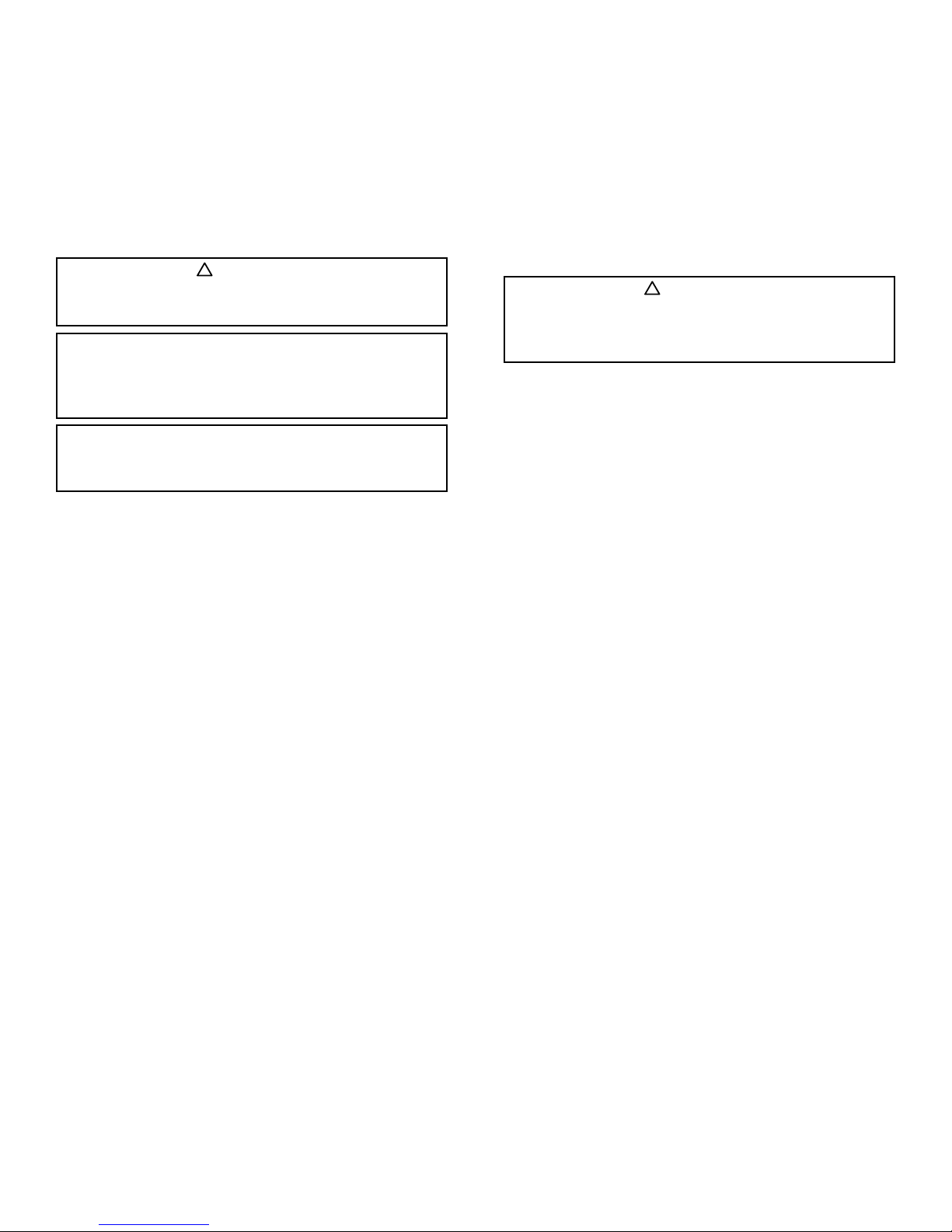
CAUTION
Venmar CES equipment is not designed to be used for
temporary heating, cooling and/or ventilation during
construction.
VCES-ASTON-IOM-1D – EnergyPack, ERV5000–10000, HRV3000–10000 9

Roofcurbs Supplied by Venmar CES (External Applications Only)
Roofcurbs supplied by Venmar CES should be mounted as
follows:
• The roofcurb is shipped knocked-down with assem-
bly hardware and instructions provided. The roofcurb
must be field erected, assembled and set in place by
the Installing Contractor (see Appendix A).
• Roofcurb dimensions are submitted with the unit
mechanical drawings which can also be found in the
unit control panel pocket or by calling Technical Sup-
port personnel from the Venmar CES factory.
• The cross members must be positioned as per the
roofcurb drawing to properly support the unit.
• The building structure must provide continuous struc-
tural support under the full perimeter of the roofcurb
and under all cross members.
• After the roofcurb has been assembled, ensure that
the curb dimensions suit the unit for which it is des-
ignated and also ensure that the structural supports
for the roofcurb are correct.
• Ensure that the assembled curb is square, plumb and
level to within 1/16” [1.6 mm] over the entire length.
The roofcurb must be shimmed to the building struc-
ture as required to provide continuous support under
its full perimeter and under all its cross members.
• The roofcurb must be fastened to the building structure.
• The Installing Contractor is responsible for making
the curb water-tight by caulking all roofcurb joints.
• See Appendix A for assembly instructions for stan-
dard design curbs or with optional wood nailer.
Roofcurbs Supplied by Others
Roofcurbs supplied by others must be designed with the
same dimensions, cross member arrangement and loca-
tion as per Venmar CES roofcurb drawings and must be
designed to evenly withstand perimeter and cross section
static loads.
Continuous ½”
bead ADBOND 1465
acoustical butyl sealant
Figure 1: Continuous ½” [13 mm] bead of ADBOND 1465
acoustical butyl sealant or equivalent applied to top perim-
eter of roofcurb and ½” x 1½” [13 x 38 mm] gasket with
adhesive strip applied to the bottom duct opening connec-
tions just prior to unit installation.
IMPORTANT
Venmar CES is not liable for any damages, costs or other
issues arising from roofcurbs supplied by others.
IMPORTANT
The ADBOND 1465 acoustical butyl sealant between the
unit and the roofcurb is critical for a positive air and water-
tight seal. If improperly applied this can result in air and
water leakage and poor unit performance (see Figure 1).
IMPORTANT
The following items must be completed prior to setting
the unit on the roofcurb.
• The roofcurb roofing must be completed including
insulation, cant strip, flashing and counter-flashing.
• Vertical ductwork supplied by Sheet Metal Contrac-
tor must be attached to the roofcurb cross members
and building structure, not to the unit. See Field
Fabricated Ductwork for suggested ductwork at-
tachment.
• If there is no building roof access underneath the
unit, and drain or piping connections must be made
(in the roofing), it is recommended to do so before
unit installation using the appropriate materials pro-
vided by the Installing Contractor.
• Use the ADBOND 1465 acoustical butyl sealant sup-
plied with the unit and apply a continuous ½” [13
mm] bead to the top perimeter of the roofcurb for a
positive air and water-tight seal and to ease section
movement when pulling modules together (if appli-
cable). The ADBOND 1465 acoustical butyl sealant
remains indefinitely pliable and sticky and should
only be applied just prior to unit installation to avoid
smudging.
• Use the ½” x 1½” [13 x 38 mm] polyvinyl gasket
with adhesive strip supplied with the unit and apply
it on top of the perimeter of the duct opening con-
nections.
VCES-ASTON-IOM-1D – EnergyPack, ERV5000–10000, HRV3000–10000 10

Rigging, Lifting and Assembling
Rigging, Lifting and Assembling Equipment
All rigging equipment and labor (as applicable) is provided
by the Installing Contractor as detailed below. It is highly
recommended that extra quantities of all items listed be
on hand. The rigging procedure and/or equipment used to
lift the unit may differ depending on the physical dimen-
sions of the unit, its location, the jobsite, the Installing
Contractor and Crane Operator preferences.
• Lifting crane of the appropriate capacity
• Adjustable spreader bars
• Cables (cables, chains or straps)
• Curb flashing (when required—based on roofing
construction)
• All tools required to pull the sections together
(chains, chain blocks, chain type come alongs, etc.)
• All construction equipment and labor required to
complete the work according to local codes
• Condensate and/or P-trap piping hardware
• All tools and materials required for level unit installation
• ½” [13 mm] wood shims required to set the gap be-
tween the unit base frame and the curb
Installation and Assembly Materials
All materials for sealing the unit to the top of a factory
supplied roofcurb, for assembling a multi-sectional unit
as detailed below and per the instructions that follow are
supplied by Venmar CES and located inside one (or more)
of the unit sections, where this (yellow) label, as shown
below, is applied on the door.
For Single Section Units
• ADBOND 1465 acoustical butyl sealant or equivalent
(applied to top perimeter of curb just prior to unit
installation).
• Polyvinyl gasket with adhesive strip (½” x 1½” [13 x
38 mm] x required length) applied on duct opening
connections.
For Multi-section (Modular) Units
• ADBOND 1465 acoustical butyl sealant or equivalent
(applied to top perimeter of curb or to the top pe-
rimeter joint of a horizontally split indoor unit lower
section just prior to unit installation). The use of
ADBOND 1465 acoustical butyl sealant or equivalent
is required to create a proper seal to minimize the
risk of water infiltration and ease section movement
when pulling modules together. Do not use the
butyl sealer on the exterior split section joints as it
remains pliable, sticky and should it become smeared
is difficult to clean.
• Polyvinyl gasket with adhesive strip (½” x 1½” [13 x
38 mm] x required length) applied between unit sec-
tions (for split section joints and duct opening con-
nections).
• 3/8” x 4” Grade 5 full thread zinc plated bolts, with
two washers and one nut each (to secure sections
together).
• Adseal 1800 series (from Adchem Adhesives) clear
silicone based sealant or equivalent (for side joint and
top joint).
• Roof seam ends made of metal with applied gasket.
• Roof joint caps x required length.
• Self-drilling 5/16 hex head #12-14 x 1” zinc plated
screws with rubber washer (for roof caps).
Rigging, Lifting and Assembling Instructions
Depending on size, the unit or unit sections of a multi-
section (modular) unit will arrive at the jobsite on a stan-
dard flatbed or special low bed trailer. Each unit or unit
section is identified with labels, as per the mechanical
drawings. At ground level, ensure that any crating used
for shipping purposes is removed if there is a possibility
that it will interfere with the placing or assembling of the
unit or unit sections on the roofcurb, structural steel or
housekeeping pad.
IMPORTANT
• Carefully read all the instructions contained herein.
Before proceeding with any work, correlate these
instructions with the information provided on the
curb and equipment shop drawing for the specific
project.
• These instructions outline the suggested method of
rigging, lifting and installing a Venmar CES unit. All
local codes and fire regulations must be verified and
adhered to by the Installing Contractor.
• Before assembling, hoisting or setting any pieces of
the supporting curbs or units, verify that the proper
unit is being directed to the correct location, as des-
ignated by the architectural and engineering design
drawings.
• Safety first: ensure that all safety practices recom-
mended by local safety associations are continu-
ously in use.
• If any questions arise during the installation proce-
dure, please contact the factory.
• The Installing Contractor is responsible for the unit
being air and water-tight at the joints between sec-
tions and between the roofcurb and the unit.
• All holes that have been made by the Installing or
Electrical Contractor after receiving and installing
the unit must be well sealed to prevent air and/or
water infiltration.
IMPORTANT
• Installation and assembly materials are in this section.
• Before setting unit on a roofcurb or structural sup-
port, read and follow the Rigging, Lifting and As-
sembling Instructions in the Installation, Operation
and Maintenance Instructions Manual.
VCES-ASTON-IOM-1D – EnergyPack, ERV5000–10000, HRV3000–10000 11

Unit or unit sections shall be lifted by cables attached to all
the lifting lugs. Consult the mechanical drawings located
in the pocket of the control panel for the number of lift-
ing lugs, number of sections and unit weight. For multi-
section (modular) unit check for additional lugs located
between split sections. Lifting lugs are factory bolted to
the unit or unit section base.
When lifting the unit or unit sections, use adjustable
spreader bars, pulleys, cables (straps or chains) in order
to properly distribute the load, applying an even vertical
lifting force only at all the lifting lugs to prevent structural
damage to the unit or unit section or prevent cables from
rubbing against the cabinet (see Figure 2). Provide ad-
ditional blocking and coverings (as required) to prevent
damage to the unit finish and/or components. The adjust-
able spreader bars are required to maintain a clearance
between the cables and the unit or unit section of at least
12” [305 mm] beyond the sides. Venmar CES will not be
responsible for any damage caused to the unit casing dur-
ing the lifting process. Main areas where damage may
occur are: electrical panels, filter gauges, rain gutters,
hoods, roofing corners, door handles and paint finish. The
lifting point must be at the center of gravity to ensure that
the unit or unit section is level during hoisting and prior to
setting. When commencing to hoist, take up the slack in
the hoisting cables slowly and gradually increase the cable
tension until the full unit or unit section weight is sus-
pended. Avoid sudden, jerking movements. Do not permit
the unit or unit section to be suspended by the lifting lugs
for an extended period of time. Once the unit or unit sec-
tion leaves the trailer ensure it is level at all times.
1. Set the unit, unit end or a bottom half of a horizontal
split unit end section with bottom duct connection of
a multi-section (modular) unit in place first.
IMPORTANT
For multi-section (modular) units, make certain to always
rig, lift and install an end section with bottom duct con-
nection first.
CAUTION
All lifting lugs provided must be used when rigging units
or unit sections. Rigging and lifting unit or unit sections
without using all lifting lugs provided will compromise
the structural integrity of the unit or unit section. Never
lift, rig or ceiling suspend from the top of the unit or unit
sections. Using a forklift or similar device for moving, lift-
ing or rigging unit or unit sections is prohibited.
Adjustable
spreader bars (typ.)
Pulleys (typ.)
See Detail A
Detail A
Use clevis and
clevis pin to attach
cable to lifting lugs.
Figure 2: Use adjustable spreader bars, pulleys and cables
attached to all lifting lugs to apply an even lifting force.
12” 12”
12” min.
Pulleys
Adjustable
spreader bars
IMPORTANT
The unit or a unit end section with bottom duct con-
nection of a multi-section (modular) unit must be set
onto the curb first such that a gap of ½” [13 mm] is left
between the curb and the unit base frame on all outer
sides, as shown in Figure 3. Use ½” [13 mm] wood shims
to set the gap as shown in Figure 4. This is important, as
it will later on prevent the first section from sliding on the
curb towards the next sections, when pulling the multi-
section (modular) unit together and align the duct con-
nection of the unit with the curb. Figure 4 shows a curb
mounted unit installation where the curb sits inside the
unit perimeter base and the unit base overhangs the curb
to prevent water entry.
For structural steel or pad mounting, if the dimensions of
the support is larger than the curb, then the end section
base must be positioned so the duct connection lines up
properly and then fastened to the structural steel or pad
to prevent the end section from moving when pulling
sections together. Fastening method must be determined
by the Installing Contractor. The lifting lugs on the out-
side perimeter may be removed with bolts and internal
nuts used to fasten unit to structural steel or pad. All
bolts should be returned and sealed to prevent leakage.
VCES-ASTON-IOM-1D – EnergyPack, ERV5000–10000, HRV3000–10000 12

Assembling a Multi-section (Modular) Unit
Special attention must be taken to ensure that a multi-
section (modular) unit has an air and water-tight seal at
every section split. Follow the next set of instructions for
assembling a multi-section (modular) unit.
2. For a horizontally split indoor unit or section:
a. Apply a continuous ½” [13 mm] bead of ADBOND
1465 acoustical butyl sealant on the top perimeter
of the lower or bottom section 1½” [38.1 mm]
from the outer edge as shown in Figure 5a.
b. Set the upper or top section over the lower sec-
tion lining up the bolt holes in the perimeter
flanges for a horizontally split indoor unit or sec-
tion (see Figure 5b).
c. Use the 3/8” x 4” bolts, nuts and washers to secure
the upper or top section to the lower or bottom
section as shown in Figure 5c. Gradually tighten
all bolts to apply an even load along the external
joints (not at any point).
3. Remove the yellow lifting lugs located on the section joint
(if any) once the first section is set in place.
4. Set the second section approximately 6” [152 mm] from
the first section (see Figure 6). If second section has
a horizontal split, the top section must be installed as
IMPORTANT
Yellow lifting lugs located on the section joint (if any)
must be removed once the first section is set in place to
allow the next section to be pulled to the first.
CAUTION
Do not over tighten joint bolts as this may cause the bot-
tom section frame to warp and break the air-tight seal.
Temporary ½”
wood shim
(supplied by contractor)
Figure 4: Use ½” [13 mm] wood shims on outer sides to
properly position and/or to prevent movement when pull-
ing multi-section (modular) units together.
Figure 3: Set unit or an end section with bottom duct con-
nection of a multi-section (modular) unit first using ½” [13
mm] wood shims on outer sides to properly position and
to prevent movement when pulling sections together.
½” [13 mm] bead of
ADBOND 1465
acoustical butyl sealant
1½”
1½” Detail at A
Figure 5a: Apply a continuous ½” bead of butyl sealer on
the top perimeter of the lower or bottom section.
A
Figure 5b: Set the upper or top section over the lower sec-
tion lining up all the bolt holes in the perimeter flanges.
Figure 5c: Use the 3/8” x 4” bolts ,nuts and washers and
gradually tighten to apply even load to secure sections.
VCES-ASTON-IOM-1D – EnergyPack, ERV5000–10000, HRV3000–10000 13

per procedure #2 above before proceeding. Use ½”
[13 mm] wood shims on outer sides to properly posi-
tion and to prevent movement when pulling multi-
section (modular) unit together when mounted on a
roofcurb. Remove the yellow lifting lugs located on
the section joints (if any) from the second section to
allow sections to be pulled together.
5. Corner reinforcement brackets or angle bars may have
been used to support multi-section (modular) unit
walls during transportation, rigging and lifting at the
split. The brackets shown in Figure 7 are for larger
units. Simple angle bars are used for smaller units
(not shown). The corner reinforcement brackets or
angle bars are no longer required after rigging and
lifting and must be removed.
6. Verify that these two sections are aligned square at the
joint in all three directions.
7. Install the ½” x 1½” [13 x 38 mm] polyvinyl gasket
with adhesive strip directly on one side of the split
section perimeter frames and middle interior parti-
tions as shown in Figure 8a through Figure 8e.
IMPORTANT
Make sure to have full contact between strips wherever a
discontinuity is present, for air and water-tightness.
IMPORTANT
After the corner reinforcement brackets or angle bars
have been removed from the split section, set the screws
along with the rubber washers that were holding the
brackets or angle bars back in place for water-tightness.
6” max.
Figure 6: Set the next section approximately 6” [152 mm]
from the first section.
Figure 7: Corner reinforcement brackets or angle bars to
be removed from the split section. Reset the screws with
rubber washer in place for water-tightness.
Figure 8: General gasket layout
8a, 8c
8d, 8e
8b
½” x 1½”
polyvinyl gasket
¼”
Figure 8a: Install a polyvinyl gasket strip on each vertical outside wall
¼” [6.4 mm] from the outside side edge from top to bot-
tom of the side joint. When compressed, a small gap will
remain which will allow the Adseal 1800 series silicone
based sealant or equivalent to seal the vertical side edges
(explained in Figure 11).
Top of
frame
Bottom
of frame
Figure 8b: Install two horizontal polyvinyl gasket strips
along the base frame, one at the top and one at the bot-
tom of the base frame, between the two vertical side gas-
ket strips so there is full contact between gasket strips for
air and water-tightness.
VCES-ASTON-IOM-1D – EnergyPack, ERV5000–10000, HRV3000–10000 14

8. Use tools (chains, chain blocks, chain type come along,
etc.) connected to the side lifting lugs (attached to
the base) on both sides of the unit to pull the second
or next section to the first end section evenly until
both sections are ¼” [6.4 mm] apart on the full joint
perimeter as in Figure 9. Remove any exterior lifting
lugs that interfere with the chains for pulling sections
together. When joining sections together, always
apply the pulling force to the lifting lugs attached
to the unit structural base, never to the corner posts
and pull uniformly from both sides of the unit sec-
tion. The butyl sealer previously applied on the roof-
curb top surface will allow the unit section to slide
into position.
9. With the sections pulled together, use the 3/8” x
4” bolts, nuts and washers to secure the sections
together along the sides as in Figure 10. Start at the
bottom and gradually tighten all bolts to apply an
even load along both sides and for indoor units along
the top (not at one place) until sections or gasket is
compressed within ¼” [6.4 mm].
CAUTION
Do not over tighten the side bolts as this may cause the
corner posts to warp and break their air and water-tight
seal.
IMPORTANT
Unit sections must be drawn together using the lifting
lugs attached to the unit structural base only.
CAUTION
Do not use the vertical side casing framing or bolt holes
to pull sections together as this may cause the corner
posts to warp and break their air and water-tight seal.
Figure 8c: Install one horizontal polyvinyl gasket strip
along the top frame between the two vertical side gasket
strips so there is full contact between gasket strips for air
and water-tightness.
Middle
internal
partition(s)/divider(s)
Figure 8d: Where two or more internal air tunnels/corridors are pres-
ent, install the gasket strips on the middle internal hori-
zontal and/or vertical partition(s)/divider(s), between the
perimeter gasket strips so there is full contact between
gasket strips for air and water-tightness.
Figure 8e: Where a multi-sectional indoor unit with verti-
cal and additional horizontal splits join, the middle internal
horizontal partition will require three gaskets. One at the
top of the bottom section and two at the bottom frame of
the top section.
Displacement
Tools supplied
by others
Figure 9: Use tools (chains, chain blocks, chain type come
along, etc.) hooked to the unit lifting lugs attached to the
structural base on both sides of the unit to pull the second
or next section to the first section evenly.
VCES-ASTON-IOM-1D – EnergyPack, ERV5000–10000, HRV3000–10000 15

10. After two sections are assembled, verify that the assem-
bly is level and square. If an adjustment is required,
make certain to address it immediately, not at the
end of the final assembly.
11. If multi-section unit has more than two sections, follow
Steps 2 through 9 for each additional section, always
pulling the next section from the first end section.
12. Apply a generous bead of Adseal 1800 series clear
silicone based sealant or equivalent to the exterior
side frame joint seams sufficiently to completely
cover the section split gasket and in such a way that
the silicone bead meets with both frames as in Figure
11. The bead of clear silicone based sealant should
fill the ¼” gap, as shown in Figure 11.
13. Install the roof joint caps with self-drilling screws in all
pre-punched holes for an air and water-tight seal
as shown in Figure 12a and Figure 12b (for outdoor
units only).
If unit is wider than 138” [3,505 mm], roof slope is
double pitched from center and two or more roof
joint caps will be supplied (see Figure 12c).
Figure 10: Secure the sections pulled together with bolts,
nuts and washers. Do not over tighten.
¼” bead Adseal
1800 clear silicone
based sealant
Figure 11: Apply a continuous bead of Adseal 1800 clear
silicone based sealant or equivalent to the exterior side
frame joints and for indoor units along the top frame joints.
Note: Cap should be on same j oint.
Figure 12a: Install the metal roof seam end with applied gas-
ket by applying a 45° force to it until the neoprene is fully
compressed. Lock into position with two self-drilling 5/16”
hex head #12-14 x 1” screws with rubber washer until the
rubber washer is compressed. Repeat for other end.
Figure 12b: Always install the roof joint cap(s) end with two side-
by-side pre-punched holes on the lower side of the roof
slope. Center and install the roof joint cap(s) with self-drill-
ing 5/16” hex head #12-14 x 1” screws with integrated
gasket until the gasket is compressed in all pre-punched
holes.
Figure 12c: Install middle joint cap at each roof joint cap
junction(s).
VCES-ASTON-IOM-1D – EnergyPack, ERV5000–10000, HRV3000–10000 16

14. All lifting lugs removed on the exterior of the base
for pulling sections together must be returned or if
not desired the bolts must be set back in place. Once
removed, the bolts must be returned and sealed with
clear silicone based sealant for water-tightness. All
other lifting lugs from the unit base may be removed,
if desired, or left in place. When removing lifting
lugs on the exterior of the base, set the bolts back
in place and seal with clear silicone based sealant for
water-tightness.
15. Touch-up paint for scratches or marks to the external
finish incurred during shipment or installation can
be obtained in the fastest amount of time in bulk or
spray cans from a local paint supplier by providing
the universally recognized RAL code. To match the
Venmar CES standard grey specify color RAL K7 Clas-
sic #RAL7001, two-component polyurethane paint
with a gloss of 30+/−4.
Paint cans (11 ounces) matching the Venmar CES
grey can also be obtained in a slower amount of time
by contacting the following paint suppliers listed
below and providing the item number, item name
and Vendor number below or through Venmar CES
after sales service by: email to Tech Support at ven-
[email protected], fax 899-319-2612 or
phone 1-866-4-VENMAR.
In Canada
Sunamco
360 Gleme Rue C.P 280
Daveluyville, Quebec G0Z 1C0
Phone: 1-866-815-4080
Contact: Audrey Mallhot
Item number: 500049624
Item name: Canette peinture grise RAL7001
Vendor number: VEN00002429
In USA
Using the universally recognized RAL code
(RAL7001), Venmar CES Grey paint can be obtained
from your local supplier.
Indoor Suspended Installation
To install indoor units that will be permanently suspended,
the units must be set on structural steel beams that are
supported by vertical rods. Venmar CES recommends
beams under the full perimeter and all cross members re-
quiring support. In addition to these recommendations, a
Structural Engineer must be involved to properly size the
supporting structural elements. Note that the locations of
the beams shall be coordinated with the location of access
doors to prevent any interference (see Figure 13). Single
section unit shown; for multi-sectional unit suspension,
consult factory.
Anchor
40”
min.
40”
min.
Figure 13: Indoor suspended installation
Hood Installation
If the intake or exhaust air hoods for the unit have been
shipped separately, they are assembled and fitted with
lifting plates for hoisting into position and holes are pre-
punched into the hood flanges for mounting. Apply a con-
tinuous length of 1/8” x 1” [3.2 x 25.4 mm] neoprene Soft
Seal gasket with adhesive strips to the hood flange perim-
eter and install with the 3/8” hex head #12–14 x 1” self-
drilling zinc plated screws supplied. Then apply a bead of
Adseal 1800 clear silicone based sealant or equivalent to
the outside perimeter of the hood flange for a water-tight
seal to the unit casing. If the hood lifting plate extension
is not desired, remove hood lifting plates, turn 180° and
screw back in place to fill holes to maintain paint finish.
VCES-ASTON-IOM-1D – EnergyPack, ERV5000–10000, HRV3000–10000 17

Field Fabricated Ductwork
On outdoor bottom vertical duct connections, support all
ducts to the roofcurb and building structure. Do not sup-
port ductwork from the unit.
See Figure 14a for a curb mounted outdoor unit. Sug-
gested methods of attaching ductwork to bottom of out-
door unit are as follows.
• Attach ½” x 1½” polyvinyl gasket with adhesive back
to ductwork flanges and fasten ductwork flanges
with self-drilling sheet metal screws to bottom frame
of unit duct opening where access to bottom of unit
is available once unit is installed. Ductwork must be
supported by building structure.
• Field provide and install ductwork supports across pe-
rimeter curb frame and/or cross members level with
top of perimeter curb, install ductwork plenums with
top perimeter flanges in supports and fasten with
self-drilling sheet metal screws. Attach ½” x 1½”
polyvinyl gasket to ductwork flanges prior to setting
unit on roofcurb.
• Field provide and install ductwork curb level with
top of perimeter curb, install ductwork plenums in
ductwork curb with top perimeter flanges and fas-
ten with self-drilling sheet metal screws. Attach ½”
x 1½” polyvinyl gasket to ductwork flanges prior to
setting unit on roofcurb.
On horizontal or indoor vertical duct connections, make
connections to the casing by applying Adseal 1800 silicone
based sealant or equivalent around the connection and
screwing flanged ducts directly to the casing and/or flange
with self-drilling sheet metal screws. It is important to seal
all duct connections to prevent air leakage and system
performance problems. Ductwork must be supported by
the building structure.
For bottom ductwork connections on pad or support steel
mounted indoor units, if the pad is larger than the inside
base frame of the unit, the bottom duct opening frame
is 1” above the bottom base of the unit (see Figure 14b).
If there is no access available to fasten ductwork flanges
with self-drilling sheet metal screws to the bottom frame
of unit duct opening, the pad opening must match the
ductwork opening and be raised by 1” to allow flanges on
ductwork plenums to seal to the bottom opening frame as
described for outdoor units.
For duct connection sizes, see the mechanical drawings.
Insulate and weatherproof all external ductwork, joints
and roof openings with counter-flashing and mastic in
accordance with applicable codes. Ductwork running
through roof decks must comply with local fire codes.
Ducts passing through unconditioned spaces must be insu-
lated and covered with a vapor barrier. Flexible connectors
should be installed close to the unit in the duct leading to
occupied spaces to minimize noise transmission.
The design of the ductwork immediately downstream of
the gas-fired furnace is critical for successful applications.
Poorly designed ductwork can contribute to excessive
temperature fluctuations. Avoid splitting or branching of
the ductwork immediately downstream or within five duct
diameters from the discharge where temperature stratifi-
cations may exist.
The design of the ductwork immediately downstream of
a double width forward curved or backward inclined fan
is critical to the performance of the fan. The velocity pro-
file at the outlet of the fan is not uniform and an elbow
located at or near the fan outlet will, therefore, develop
Figure 14a: Bottom field fabricated ductwork connection
for outdoor curb mounted units
½” x 1½” polyvinyl gasket
Figure 14b: Bottom field fabricated ductwork connection
for indoor pad mounted units
½” x 1½” polyvinyl gasket
1”
VCES-ASTON-IOM-1D – EnergyPack, ERV5000–10000, HRV3000–10000 18

a pressure loss greater than its ”handbook” value and
must be included in the external static pressure calcula-
tions. Consult the AMCA Fan Application Manual publica-
tion 201 for recommendations and system static pressure
losses.
The ventilation system should be designed according to
maximum airflow needs. To minimize noise level and loss
of pressure, ducts should be designed for a maximum air
velocity of 1,200 feet per minute, keeping the direction
and transition changes to a minimum. To further reduce
noise transmission, line the first 15 feet [4,572 mm] of
duct with acoustic insulation. Elbows with a turning radius
equal to or greater than one, or 90° elbows with turning
vanes, should also be used.
When an Energy Recovery Ventilator (ERV) is installed in
conjunction with a forced air system Air Handling Unit
(AHU), the AHU and network of ducts are used to sup-
ply fresh air inside the building. In this type of system, the
main fan of the AHU must be in continuous operation
when the ERV is on. Supply air from the ERV should be
introduced into the return duct of the AHU no less than 6
feet [1,829 mm] upstream from the AHU. The ERV return
duct connection should be at least 2 feet [610 mm] up-
stream of the ERV supply air duct connection in the AHU
return duct.
Electrical Connections
The unit is factory wired (unless otherwise specified)
except for power connections, shipping split locations,
shipped loose sensors/items or remote control options
as indicated in the electrical schematics and sequence of
control. The unit may or may not have an optional factory
installed door interlocking disconnect in the control panel.
If the unit control panel disconnect is not supplied, the
Electrical Contractor must provide and install disconnect
outside of the unit as per local electrical codes and run the
power supply wiring to the control panel.
• For multi-section (modular) units, the Electrical Con-
tractor must join the low and high voltage wiring be-
tween sections at the junction boxes or extend coiled
wiring.
• Check nameplate for correct power supply requirements.
• See electrical schematics and sequence of control
located in the control panel pocket for field wiring of
power connections, shipped loose sensors, items or
remote control interlocks. The Electrical Contractor
must locate, install and wire sensors, items or remote
control interlocks as per electrical schematics and se-
quence of control.
• Numbered terminals strips are included in the control
panel for ease of connection and service.
• All field wiring and components must comply with
NEC and local requirements. In Canada, electrical
connections must be in accordance with CSA C22.1
Canadian Electrical Code Part One.
• Install copper wiring of proper size to handle current
load.
• The base unit control includes an external contact
and is not equipped with a remote control panel.
This contact is located in the unit control panel. The
Installer must connect the external contact to a con-
troller normally located in the building. This controller
can be a humidistat, switch or timer, etc. Optional
controls are 24 VAC.
• The remote control panel is optional and when in-
cluded has numbered terminals matching the unit
control panel terminals. Use wiring equal to AWG18
to connect like-numbered terminals.
• Mounting of field provided components in the con-
trol panel is allowed as long as their space was con-
sidered during the submittal process. Non-considered
electrical components are not allowed in the control
panel. It is the responsibility of the Control Contrac-
tor to provide his own power source(s) for any field
added electrical components. The control panel
mounted transformers are not rated for external
components power supply unless otherwise listed on
the electrical schematics.
!
WARNING
When installed, the unit must be electrically grounded in
accordance with local codes or, in the absence of local
codes, with the National Electrical Code, ANSI/NFPA70,
and/or the Canadian Electrical Code CSA C22.1. Unit
cabinet must have an uninterrupted, unbroken electrical
ground to minimize the possibility of personal injury if an
electrical fault should occur. Failure to follow this warn-
ing could result in the Installer being liable for personal
injury of others.
IMPORTANT
Wire nuts and electrical butt connectors (if required) must
be supplied by the Electrical Contractor.
VCES-ASTON-IOM-1D – EnergyPack, ERV5000–10000, HRV3000–10000 19

Electrical Field Connections
Shipped loose sensors, items or remote control wiring
can be located next to the power feed cable provided it
is inserted in shielded cable that will protect it from elec-
tromechanical interference. Ensure the power feed cable
ground is securely connected to the terminals located in
the control panel.
Electrical Contractor must provide wiring for controls that
are supplied optionally and shipped loose or field supplied.
Mark the electrical schematic with the connections com-
pleted and leave them with the unit for start-up and service.
Coil, WSHP or Humidifier Piping Connections
Connections to the unit coil (water, steam or non-inte-
grated direct expansion, WSHP or humidifier) are by oth-
ers. Refer to the mechanical drawings and the instructions
on the casing for correct orientation of external piping.
External supply and return piping connection, provision,
design and all other safety, freeze protection or electrical
control requirements for system operation are the sole
responsibility of the Installing Contractor and/or Design
Engineer. Refer to ASHRAE handbooks and local building
codes for correct piping and electrical control for proper
installations. Refer to the mechanical drawings for coil per-
formance design information.
For WSHP units see Appendix B for recommended piping
and electrical control components. See the piping sche-
matics for optional piping components and sequence of
operation for electrical control options or interlocks sup-
plied with the unit.
CAUTION
Internal coil (water, steam or non-integrated direct
expansion), WSHP or humidifier piping connections
within the unit may only be field extended through the
cabinet within designated areas. The unit cabinet and/
or floor must be wisely penetrated in order to keep their
integrity. Access openings in the floor can only be cut
or drilled for piping and wiring (high and low voltage)
in the designated rectangular areas within an upturned
1” [25.4 mm] flange as provided during the submittal
process and located on the mechanical drawings. Access
openings must be sized, field cut or drilled by the Install-
ing Contractor within the rectangular flanged area then
sealed air and water-tight. If insulation was removed to
create floor access openings, insulation must be put back
in place to avoid condensation. Do not cut or drill holes
through floor of unit in non-designated areas without
consulting the factory first. The structural integrity of the
floor may be compromised and possible leaks develop.
CAUTION
A water and glycol mixture is used for factory tests and
to prevent any possibility of freezing during transit and/
or storage. In units that include factory installed water
piping, some glycol may remain in the system. Flush the
system in the field, prior to installation, if no glycol traces
are desired. In low temperature applications, the water
supply line and return line should be insulated to prevent
condensate and an antifreeze solution should be used to
protect water-to-refrigerant heat exchanger from freez-
ing damage.
IMPORTANT
A hydrostatic test must be performed in the field by the
Installing Contractor at 1.2 times the operating pressure
on all equipment involving piping connections to verify
that the installed unit and its connections to the network
are free of leaks prior to the unit being set in operation.
This test shall be performed after the unit is completely
piped to the network and shall cover the connections
between the unit and the network, as well as all internal
components of the unit.
CAUTION
High voltage power lines, shipped loose sensors, items
or remote control option field wiring entry points may
only be field extended through the cabinet within des-
ignated areas. The unit cabinet and/or floor must be
wisely penetrated in order to keep their integrity. Access
openings in the floor can only be cut or drilled for piping
and wiring (high and low voltage) in the designated rect-
angular areas within an upturned 1” [25.4 mm] flange
as provided during the submittal process and located on
the mechanical drawings. Access openings must be sized,
field cut or drilled by the Installing Contractor within the
rectangular flanged area then sealed air and water-tight.
If insulation was removed to create floor access openings,
insulation must be put back in place to avoid condensa-
tion. Do not cut or drill holes through floor of unit in
non-designated areas without consulting the factory first.
The structural integrity of the floor may be compromised
and possible leaks develop.
CAUTION
Electrical components and contacts must be protected
from damaging metal shavings before drilling holes into
the control panel. Use liquid-tight connections through
the control panel and unit casing eliminating any water
and air penetration.
VCES-ASTON-IOM-1D – EnergyPack, ERV5000–10000, HRV3000–10000 20
This manual suits for next models
1
Table of contents
Other Venmar Air Conditioner manuals
Popular Air Conditioner manuals by other brands

Fuji Electric
Fuji Electric RD-60FA Service manual

Haier
Haier HSU-10VNJ17 Operation manual

Frigidaire
Frigidaire FFMS121CQ10 installation manual

Daikin
Daikin Super Multi NX 3MKS50E3V1B Service manual

Mitsubishi Electric
Mitsubishi Electric MFZ-KW25VG installation manual

Amana
Amana PTAC 24" Maintenance manual