Venmar HRV CONSTRUCTO 1.5ES User guide

HRV CONSTRUCTO 1.5ES*
(PA RT NOS 46110 AND 1601702)
HRV CONSTRUCTO 2.0ES*
(PA RT NO. 47110)
ERV CONSTRUCTO 2.0ES
(PA RT NO. 47115)
HRV SOLO 1.5ES*
(PA RT NOS 46720 AND 46725)
HRV SOLO 2.0ES*
(PA RT NO. 47720)
* THESE PRODUCTS EARNED THE ENERGY STAR®BY MEETING STRICT ENERGY EFFICIENCY GUIDELINES SET BY
NATURAL RESOURCES CANADA AND THE US EPA. THEY MEET ENERGY STAR REQUIREMENTS ONLY WHEN
USED IN CANADA.
INSTALLER MANUAL
READ AND SAVE THESE INSTRUCTIONS
RESIDENTIAL USE ONLY
20503 REV. 04
VB0175 VB0176
VB0170
IMPORTANT INFORMATION FOR THIS UNIT ABOUT DRAIN
INSTALLATION IN COLD CLIMATES ON PA G E 12, SECTION 3.8.

ABOUT THIS MANUAL
Because of the large amount of models covered by this publication, the illustrations are typical ones. Some details of your unit may be
slightly different than the ones shown.
Please take note that this manual uses the following symbols to emphasize particular information:
WARNING
Identifies an instruction which, if not followed, might cause serious personal injuries including possibility of death.
CAUTION
Denotes an instruction which, if not followed, may severely damage the unit and/or its components.
NOTE: Indicates supplementary information needed to fully complete an instruction.
We welcome any suggestions you may have concerning this manual and/or the unit, and we would appreciate hearing your comments
on ways to better serve you. Please contact us by phone at 1-800-567-3855.
ABOUT THESE UNITS
LIMITATION
For residential (domestic) installation only. These units must be installed in accordance with all national and local regulations, building
codes and safety codes.
WARNING
!
!
TO REDUCE THE RISK OF FIRE, ELECTRIC SHOCK, OR INJURY TO PERSON(S) OBSERVE THE FOLLOWING:
1. Use this unit only in the manner intended by the manufacturer. If you have questions, contact the manufacturer at the address or
telephone number listed in the warranty.
2. Before servicing or cleaning this unit, disconnect power cord from electrical outlet.
3. This unit is not designed to provide combustion and/or dilution air for fuel-burning appliances.
4. When cutting or drilling into wall or ceiling, do not damage electrical wiring and other hidden utilities.
5. Do not use this unit with any solid-state speed control device other than following:
6. This unit must be grounded. The power supply cord has a 3-prong grounding plug for your personal safety. It must be plugged into a
mating 3-prong grounding receptacle, grounded in accordance with the national electrical code and local codes and ordinances. Do
not remove the ground prong. Do not use an extension cord.
7. Do not install in a cooking area or connect directly to any appliances.
8. Do not use to exhaust hazardous or explosive materials and vapors.
9. When performing installation, servicing or cleaning this unit, it is recommended to wear safety glasses and gloves.
10. Due to the weight of the unit, two installers are recommended to perform installation.
11. When applicable local regulation comprise more restrictive installation and/or certification requirements, the aforementioned
requirements prevail on those of this document and the installer agrees to conform to these at his own expenses.
CAUTION
1. To avoid prematurate clogged filters, turn OFF the unit during construction or renovation.
2. Please read specification label on product for further information and requirements.
3. Be sure to duct air outside – Do not intake/exhaust air into spaces within walls or ceiling or into attics, crawl spaces, or garage.
4. Intended for residential installation only in accordance with the requirements of NFPA 90B (for a unit installed in U.S.A.) or Part 9 of
the National Building Code of Canada (for a unit installed in Canada).
5. Do not run any air ducts directly above or closer than 2 ft (0.61 m) to any furnace or its supply plenum, boiler, or other heat producing
appliance. If a duct has to be connected to the furnace return plenum, it must be connected not closer than 9’ 10” (3 m) from this
plenum connection to the furnace.
6. The ductwork is intended to be installed in compliance with all local and national codes that are applicable.
7. When leaving the house for a long period of time (more than two weeks), a responsible person should regularly check if the unit
operates adequately.
8. If the ductwork passes through an unconditioned space (e.g.: attic), the unit must operate continuously except when performing
maintenance and/or repair. Also, the ambient temperature of the house should never drop below 18°C (65°F).
2
Units Optional Main Controls Optional Auxiliary Controls
Constructo Deco-Touch, Lite-Touch Constructo, Constructo Dehumidistat, 20-min. lighted push-button,
60-min. mechanical timer
Solo Altitude, Deco-Touch, Lite-Touch Constructo,
Simple-Touch Constructo, Constructo
Dehumidistat, 20/40/60-min. lighted push-button,
60-min. mechanical timer

TABLE OF CONTENTS
3
1. TECHNICAL DATA ..................................................................................................................................... 4-5
1.1 AIR DISTRIBUTION (NORMAL OPERATION) ............................................................................................................................ 4
1.2 AIR DISTRIBUTION (DEFROST MODE) .................................................................................................................................. 4
1.3 DEFROST CYCLES TABLES................................................................................................................................................. 4
1.4 DIMENSIONS.................................................................................................................................................................. 5
1.41 HRV CONSTRUCTO 1.5ES, HRV CONSTRUCTO 2.0ES, HRV SOLO 1.5ES AND HRV SOLO 2.0ES .................................................. 5
1.4.2 ERV CONSTRUCTO 2.0ES ....................................................................................................................................................... 5
1.5 SPECIFICATIONS ............................................................................................................................................................. 5
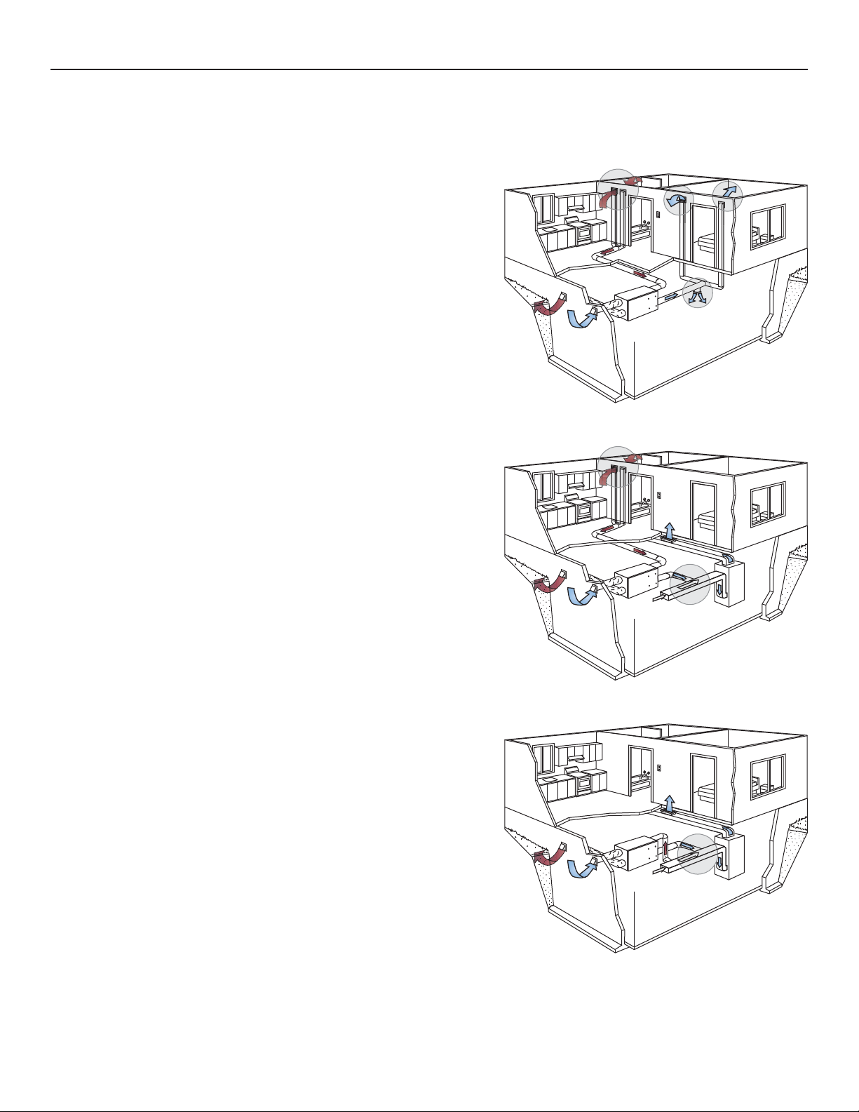
2. TYPICAL INSTALLATIONS ........................................................................................................................... 6
2.1 FULLY DUCTED SYSTEM ................................................................................................................................................... 6
2.2 EXHAUST DUCTED SYSTEM (SOURCE POINT VENTILATION) ...................................................................................................... 6
2.3 SIMPLIFIED (VOLUME VENTILATION) .................................................................................................................................... 6
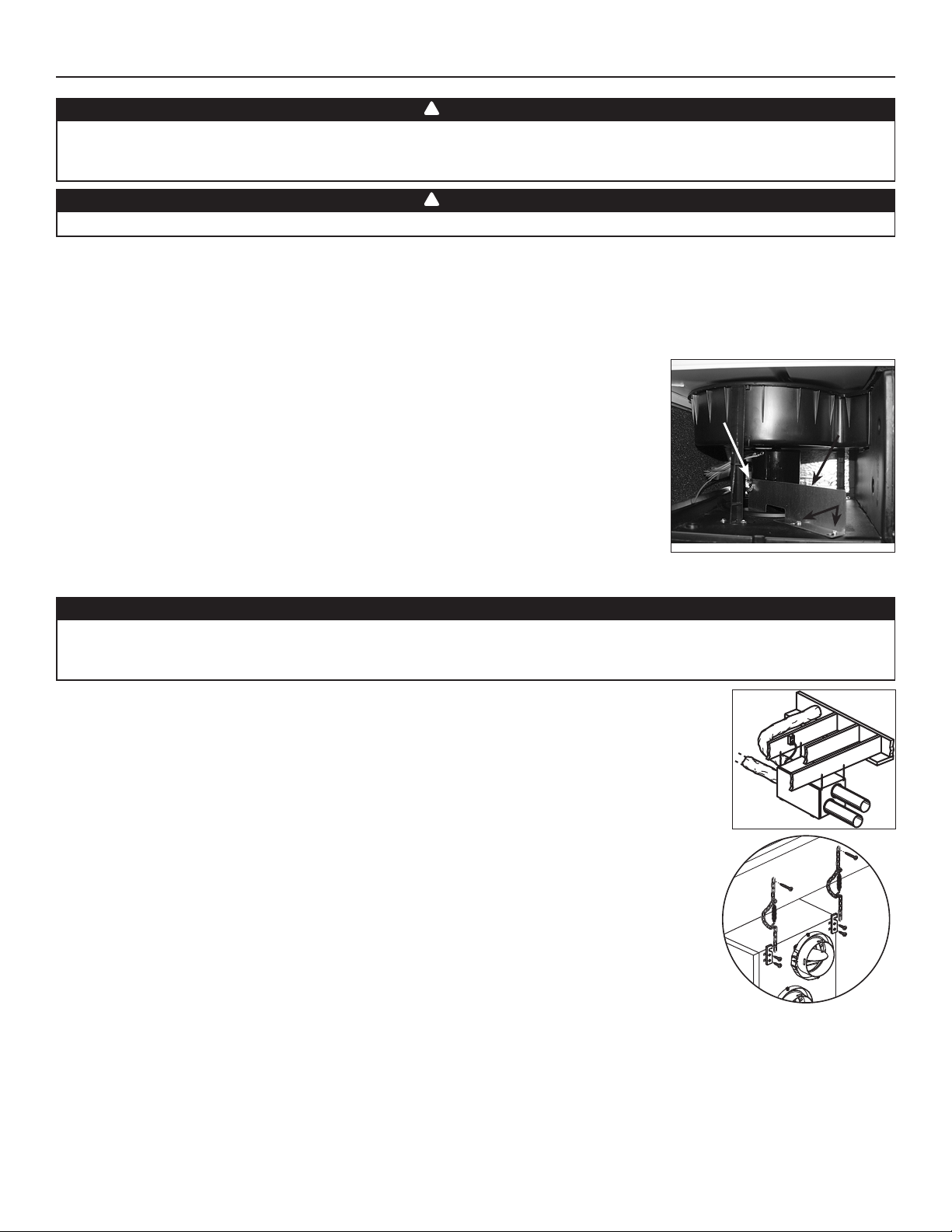
3. INSTALLATION .........................................................................................................................................7-13
3.1 INSPECT THE CONTENT OF THE BOX ................................................................................................................................... 7
3.2 LOCATING AND MOUNTING THE UNIT .................................................................................................................................. 7
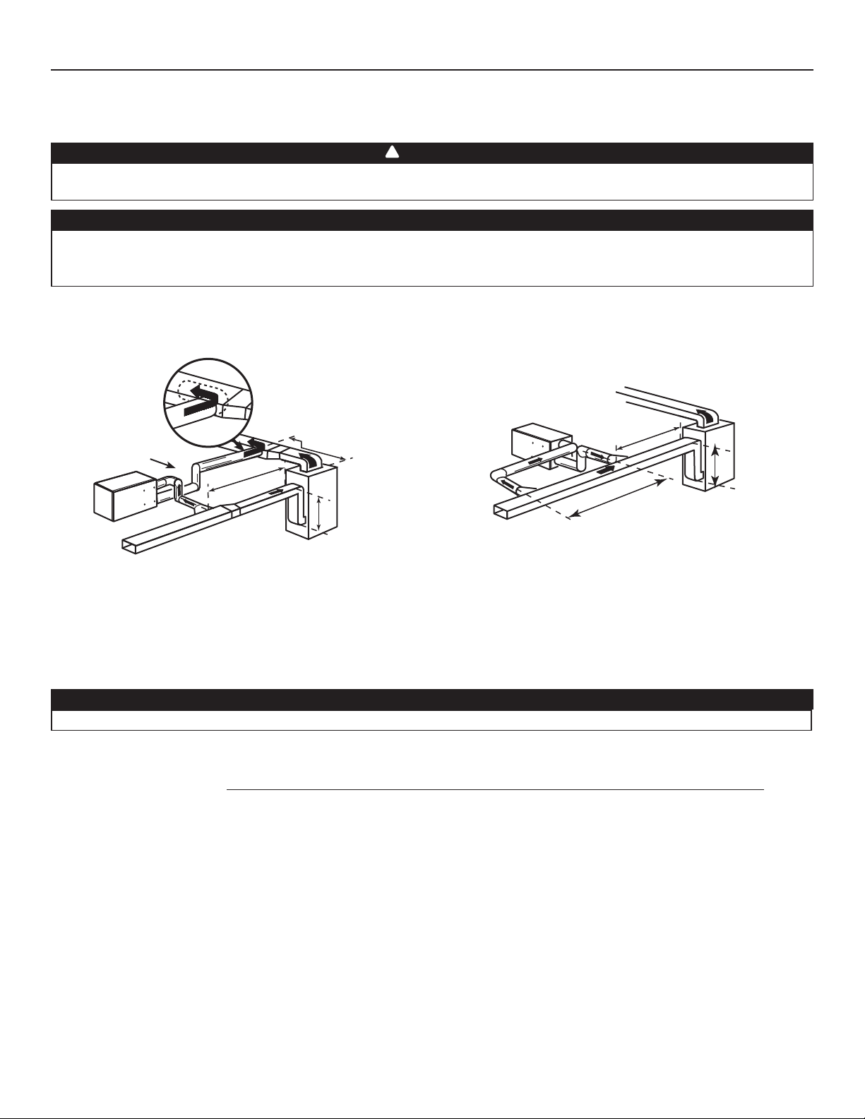
3.3 PLANNING OF THE DUCTWORK .......................................................................................................................................... 7
3.4 CALCULATING THE DUCT SIZE............................................................................................................................................ 8
3.4.1 EXAMPLE OF CALCULATION ......................................................................................................................................................... 8
3.4.2 EXAMPLE OF ADESIGN FOR AFULLY DUCTED SYSTEM ...................................................................................................................... 8
3.5 INSTALLING THE DUCTWORK AND THE REGISTERS ............................................................................................................. 9-10
3.5.1 FULLY DUCTED SYSTEM .............................................................................................................................................................. 9
3.5.2 EXHAUST DUCTED SYSTEM ......................................................................................................................................................... 9
3.5.3 SIMPLIFIED INSTALLATION ..........................................................................................................................................................10
3.6 CONNECTING THE DUCTS TO THE UNIT ............................................................................................................................. 11
3.7 INSTALLING THE EXTERIOR HOODS ................................................................................................................................... 12
3.8 CONNECTING THE DRAIN .......................................................................................................................................... 12-13
3.8.1 HRV UNITS ...........................................................................................................................................................................12
3.8.2 ERV UNIT .............................................................................................................................................................................13
4. CONTROLS ............................................................................................................................................13-15
4.1 INTEGRATED CONTROL .................................................................................................................................................. 13
4.1.1 BOOT SEQUENCE ....................................................................................................................................................................13
4.1.2 SETTING EXTENDED DEFROST ....................................................................................................................................................13
4.2 ELECTRICAL CONNECTION TO OPTIONAL WALL CONTROLS ................................................................................................ 14-15
4.2.1 ELECTRICAL CONNECTION TO ALTITUDE MAIN WALL CONTROL ............................................................................................................14
4.2.2 ELECTRICAL CONNECTION TO DECO-TOUCH MAIN WALL CONTROL......................................................................................................14
4.2.3 ELECTRICAL CONNECTION TO LITE-TOUCH CONSTRUCTO OR SIMPLE-TOUCH CONSTRUCTO MAIN WALL CONTROL.......................................15
4.2.4 ELECTRICAL CONNECTION TO CONSTRUCTO MAIN WALL CONTROL .....................................................................................................15
4.2.5 ELECTRICAL CONNECTION TO OPTIONAL AUXILIARY WALL CONTROLS ...................................................................................................15
5. ELECTRIC CONNECTION TO THE FURNACE ..........................................................................................15
6. WIRING DIAGRAM.......................................................................................................................................16
7. BALANCING THE UNIT ...............................................................................................................................17
7.1 WHAT YO U NEED TO BALANCE THE UNIT ......................................................................................................................... 17
7.2 PRELIMINARY STAGES TO BALANCE THE UNIT ................................................................................................................... 17
7.3 BALANCING PROCEDURE ............................................................................................................................................. 17
8. SERVICE PARTS .........................................................................................................................................18
9. TROUBLESHOOTING ........................................................................................................................... 19-20

1. TECHNICAL DATA
1.1 AIR DISTRIBUTION (NORMAL OPERATION)
4
1.3 DEFROST CYCLES TABLES
HRV CONSTRUCTO 1.5ES AND SOLO 1.5ES UNITS
OUTSIDE TEMPERATURE DEFROST CYCLES (MINUTES)EXTENDED DEFROST CYCLES
CELCIUS (°C) FAHRENHEIT (°F) DEFROSTING OPERATION TIME BETWEEN EACH
DEFROST CYCLES DEFROSTING OPERATION TIME BETWEEN EACH
DEFROST CYCLES
-5 23 7 50 10 30
-15 5 7 25 10 20
-27 -17 10 20 10 15
1.2 AIR DISTRIBUTION (DEFROST MODE)
VF0052
VF0053
ERV CONSTRUCTO 1.5 ES UNIT
OUTSIDE TEMPERATURE DEFROST CYCLES (MINUTES)EXTENDED DEFROST CYCLES
CELCIUS (°C) FAHRENHEIT (°F) DEFROSTING OPERATION TIME BETWEEN EACH
DEFROST CYCLES DEFROSTING OPERATION TIME BETWEEN EACH
DEFROST CYCLES
-5 23 10 60 10 30
-15 5 10 30 10 20
-27 -17 10 20 10 15
HRV CONSTRUCTO 2.0ES AND SOLO 2.0ES UNITS
OUTSIDE TEMPERATURE DEFROST CYCLES (MINUTES)EXTENDED DEFROST CYCLES
CELCIUS (°C) FAHRENHEIT (°F) DEFROSTING OPERATION TIME BETWEEN EACH
DEFROST CYCLES DEFROSTING OPERATION TIME BETWEEN EACH
DEFROST CYCLES
-5 23 6 50 10 30
-15 5 6 25 10 20
-27 -17 10 20 10 15
NOTE: The Constructo and Solo Performance Charts are listed on the specification sheets of these units.
Visit our website at www.venmar.ca to access those documents.

1. TECHNICAL DATA (CONT’D)
1.4 DIMENSIONS
5
1.5 SPECIFICATIONS
MODEL HRV CONSTRUCTO 1.5ES HRV CONSTRUCTO 2.0ES ERV CONSTRUCTO 2.0ES HRV SOLO 1.5ES HRV SOLO 2.0ES
WEIGHT 65 LB (29.5 kg) 65 LB (29.5 kg) 76 (34.5 KG) 65 LB (29.5 kg) 65 LB (29.5 kg)
PORT
DIAMETER 6˝ (152 MM) 6˝ (152 MM) 6˝ (152 MM) 6˝ (152 MM) 6˝ (152 MM)
DRAIN
DIAMETER 1/2˝ (12 MM) 1/2˝ (12 MM) 1/2˝ (12 MM) 1/2˝ (12 MM) 1/2˝ (12 MM)
INSTALLATION CHAINS AND SPRINGS (PROVIDED WITH THE UNIT)
MOTOR
SPEED HIGH AND LOW SPEED FACTORY SET (OPTIONAL INCREASED LOW SPEED)
ELECTRICAL
SUPPLY 120 V, 60 HZ120 V, 60 HZ120 V, 60 HZ120 V, 60 HZ120 V, 60 HZ
POWER
CONSUMPTION 160 WATTS 195 WATTS 200 WATTS 160 WATTS 195 WATTS
17”
(432 mm)
17¼” (438 mm)
6”
(152 mm)
Power Cord
36” (914 mm)
Door
30¼” (768 mm)
35” (891 mm)
Terminal
Block
Location
Blower
Assembly
Motorized
Damper
Hooks Location
for Hanging Chains
Heat
Recovery
Core
VK0077A
17”
(432 mm)
17¼” (438 mm)
6”
(152 mm)
Door
34” (864 mm)
39” (991 mm)
Blower
Assembly
Hooks Location
for Hanging Chains
Energy
Recovery
Core
VK0078A
Terminal
Block
Location
Motorized
Damper
Power Cord
36” (914 mm)
1.4.1 HRV CONSTRUCTO 1.5ES, HRV CONSTRUCTO 2.0ES, HRV SOLO 1.5ES AND HRV SOLO 2.0ES
1.4.2 ERV CONSTRUCTO 2.0ES
This manual suits for next models
4
Table of contents
Other Venmar Air Conditioner manuals
Popular Air Conditioner manuals by other brands

Fujitsu
Fujitsu ASYG 09 LLCA installation manual

York
York HVHC 07-12DS Installation & owner's manual

Carrier
Carrier Fan Coil 42B Installation, operation and maintenance manual

intensity
intensity IDUFCI60KC-3 installation manual

Frigidaire
Frigidaire FAC064K7A2 Factory parts catalog

Sanyo
Sanyo KS2432 instruction manual

Mitsubishi Electric
Mitsubishi Electric PUHZ-RP50VHA4 Service manual

Panasonic
Panasonic CS-S18HKQ Service manual

Panasonic
Panasonic CS-E15NKE3 operating instructions

Gree
Gree GWH18TC-K3DNA1B/I Service manual

Friedrich
Friedrich ZoneAire Compact P08SA owner's manual

Daikin
Daikin R32 Split Series installation manual