concealed within of the reveal
5. With 2-component acoustic foam
Fix VX-2K peripherally in the wall
7. Unit protection against pollution
8. Fassadenabschluss nach Fertigstellung
der Putz- und Malerarbeiten montieren
a) thereto is the enclosed, room-side protection
cover throughout the building phase
use; In addition, we recommend using of
VX-LAL-plaster cover for the flat duct
a) Room-side opening gap between wall and duct
diffusion-tight / permanently elastic sealing
(Ventomaxx assembly sealing adhesive VX-FK)
9. Inside cover only shortly before the completion
of the construction project mounting
b) um Deformationen am Gehäuse zu vermeiden,
Schrauben nur mäßig, gleichmäßig anziehen
10. Electrical connection
may only be made by a qualified electrician!
a) VBefore starting work, switch off the fuse /
Pull out the plug! Further steps like
Mounting Type LAW; see also the
following pages.
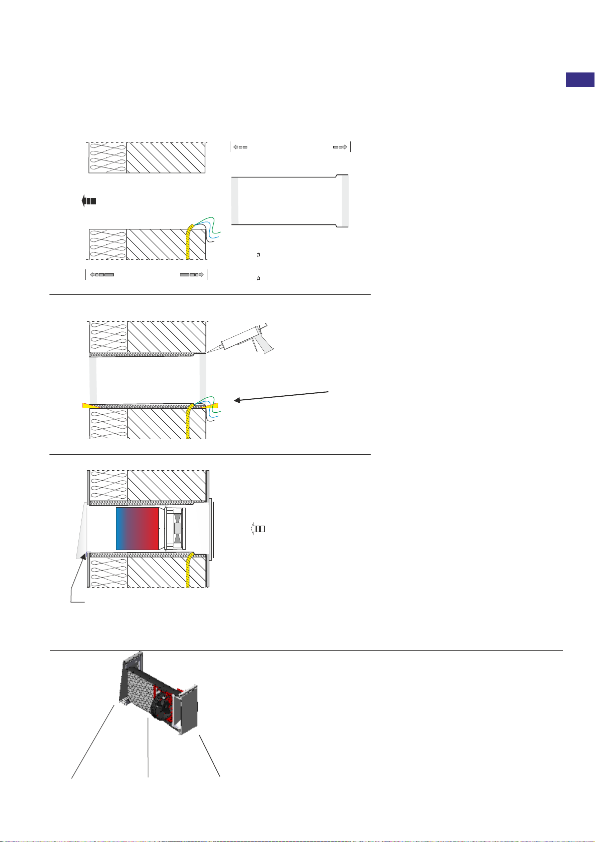
1. Preparing the wall breakthrough
a) Opening round 200 mm or square W/H
200 x 190 mm Making or prepare in
rough construction
b) damit die Systemträgereinheit mit Ventilator
während der Bauphase keinen Schaden nimmt,
sollte diese bis zur Endmontage an einem
geschützten Ort zwischengelagert werden.
a) den verstellbaren Laibungsanschluss bündig
zum späteren Putzniveau der Laibungsecke
einjustieren / umlaufend abkleben
6. Flachkanal-System innerhalb der
Dämmebene einhausen
b) Schnittstelle zwischen Flachkanal, Dämm-
ebene und Putzanschlusses mit Kompriband
andichten
4. For larger openings, cavities
additionally with rock wool, mineral wool
stuffed or isolate expertly
Preparing low voltage cabel
2x2x0,6
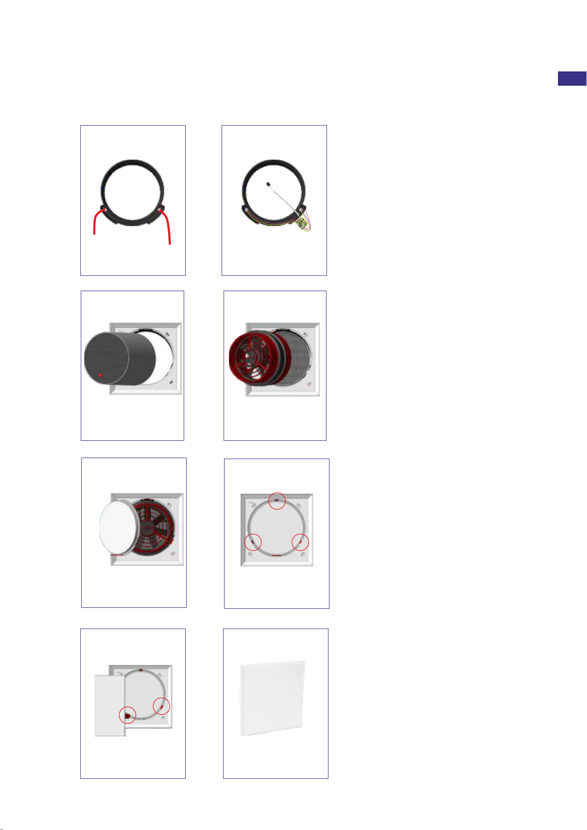
a) the room-side design panel can be applied to the
provided fixing points of the RS-LAL or attached
to the wall
2. Manufacture fan length with ring modules
(At desired location within of the reveal)
The standard ring module set is for a
Fan nominal length prepared by about 330 mm;
Ring modules possibly expand; shorten and sealing
Caution: cut only on the outside!
3. Ring Module Set push it into the wall,
aligning and fixing free of tension
c) when LAL-mounting of the telescopic unit has a
incline of approx 1.5-3 ° must be provided from
the inside to the outside; at flat duct it is 5 °(degrees)
d) Flachkanal außenbündig auf Laibungsniveau
justieren; ggf. einkürzen; mittels passendem
Flachkanalhalter an der Außenwand befestigen
Outside
View sidwise
wall thickness
Manufacture of the
total length
Slide in the operating unit
Plaster cover
RS-LAL
Inside
Outside
cut vertikally
sealing adhesive
1,5 bis 3° slope
by EPS mounting wedges
acoustically decoupled manufacturing
Ord-No: 9500-0030SP
Plaster cover
Outside
Schnitt vertikal
mounting external
wall cover and
inner housing cover
Inside
channel junction with
ventilation tape
sealing encircle
When plaster facades we recommend a flat duct insulation of approximately 30 mm.
b) Empty tube provided or low-voltage cable
2x2x0.6 acc. Wiring plan laying!
b) after adjusting the ring module set to the
Wall thickness (extending over VLE-Ring Module
and if necessary, cut the outer pipe end are still
existing connection jointless diffusion-tight seal
with VX-FK
a) beforehand the cables are in the cable bags
introducing the ring module sets
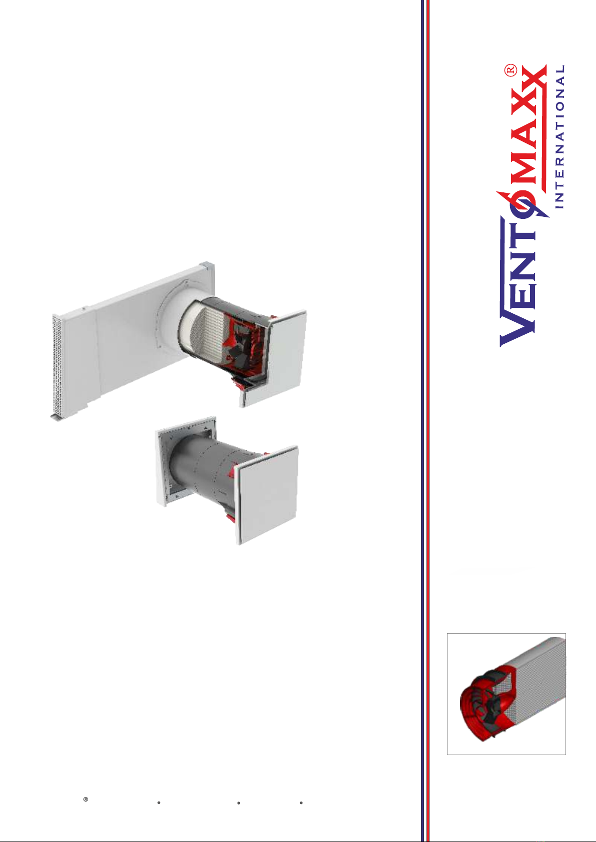
The illustration shows a
Sectional view of Z-WRG RONDO IQ
in mounted version LAL,
für die verdeckte Integration
concealed within the reveal
Flachkanalhalter FKH
3-dimensional verstellbar
Rough construction
Ring Module Se
RS-LAL
Device unit
Z-WRG RONDO IQ
telescopable façade connection
with integrated condensate drain
Facade border
FA-LAx 37
IQ-Design-Cover
› INSTALLATION INSTRUCTIONS / rough construction mounting Type LAL 7
Cut vertikal
Solid wall + insulation system
Assembly instructions - Z-WRG RONDO IQ - Mounting Type LAW