Ventry 20EM3550 User manual

OWNER’S MANUAL
POSITIVE PRESSURE VENTILATION FANS
By Ventry Solutions, Inc.
(888) 257-8967
Ventry.com

FOR POSITIVE PRESSURE ATTACK AND VENTILATION
BY
Ventry Solutions, Inc.
14128 N. Hauser Lake Road
Hauser, ID 83854 USA
(888) 257-8967 • (208) 773-1194
Fax: (208) 777-0360
Ventry.com
Thank you for purchasing a VENTRY® POSITIVE PRESSURE VENTILATION FAN made by
Ventry Solutions, Inc. Our experience as volunteer fire fighters, coupled with feedback from fire
fighters across the country, has helped make this fan the best on the market. If you have any
comments, ideas, observations or creative uses, please contact us by phone, email, mail or fax so
that we may continue to improve our product.
Fan Serial Number: _________________________________________
Fan Size/Model: ___________________________________________
Engine Serial Number: ______________________________________
Invoice Number: ___________________________________________
Invoice Date: ______________________________________________
Patent 5,503,526
Copyright 2017 Ventry Solutions, Inc., Sixth Edition
Printed August 15, 2017

ii
TABLE OF CONTENTS
FAN SPECIFICATIONS ...................................................................................................................1
OUT OF THE BOX ...........................................................................................................................3
FAN TRANSPORT ...........................................................................................................................3
One Person Carry ..........................................................................................................................3
Two Person Carry ..........................................................................................................................3
LEG ADJUSTMENT.........................................................................................................................4
How to raise the fan with one person ............................................................................................4
Another method of raising the fan, one person .............................................................................6
How to lower the fan, one person ..................................................................................................6
HOW TO USE POSITIVE PRESSURE VENTILATION ................................................................7
PPV The Basics .............................................................................................................................7
Placement ......................................................................................................................................8
Smoke Ejection ..............................................................................................................................8
FAN SAFETY ...................................................................................................................................8
Safety Guidelines ..........................................................................................................................8
Ground Debris Pickup / Maximum Air Volume ...........................................................................9
Stability .........................................................................................................................................9
Filling the Gas Tank ......................................................................................................................9
Backdraft Situations ......................................................................................................................9
COMMON QUESTIONS ABOUT POSITIVE PRESSURE ...........................................................10
Why positive instead of negative pressure ventilation? .............................................................. 10
When should positive pressure not be used? ............................................................................... 10
What is the door seal and how important is it? ........................................................................... 10
What are some examples of positive pressure ventilation? ......................................................... 10
FAN COMPARISON METHODS ................................................................................................... 11
Ribbon Test ................................................................................................................................. 11
Volume Test ................................................................................................................................ 11
Thrust Test ................................................................................................................................... 11
WARRANTY .................................................................................................................................... 12
Propeller / Frame / Guard ............................................................................................................ 12
Engine .......................................................................................................................................... 12

iii
MAINTENANCE .............................................................................................................................. 12
Engine Maintenance .................................................................................................................... 12
Kevlar & Fiberglass-Coated Propeller ........................................................................................ 12
Frame Maintenance ..................................................................................................................... 12
Tachometer .................................................................................................................................. 12
TROUBLE SHOOTING ................................................................................................................... 12
Fan walks during operation ......................................................................................................... 12
Leg movement obstructed ........................................................................................................... 13
Fan too large to fit compartment ................................................................................................. 13
PARTS ORDERS .............................................................................................................................. 13
PARTS LIST FOR 20-INCH FRAME, WITH AND WITHOUT WHEEL OPTION ..................... 14
20-Inch Frame Assembly Diagram ............................................................................................. 15
PARTS LIST 24-INCH FRAME, WITH AND WITHOUT WHEEL OPTION .............................. 16
24-Inch Frame Assembly Diagram ............................................................................................. 17
PARTS LIST FOR ENGINE, TACH, AND SPARK ....................................................................... 18
Spark Arrester and Stickers, Honda GX Series Engines ............................................................. 18
Spark Arrester and Stickers, Honda GC Series Engines ............................................................. 18
Tachometer/Hour Meter .............................................................................................................. 19
PARTS LIST FOR GUARD MOUNT ............................................................................................. 20
Guard Mount Pictures ................................................................................................................. 21
PROPELLER ORIENTATION ........................................................................................................ 22
PARTS LIST FOR PROPELLER MOUNT ..................................................................................... 22
Propeller Hubs and Tab Washer Pictures .................................................................................... 23
PARTS LIST FOR FRONT OF GUARD ......................................................................................... 24
Guard Front Picture ..................................................................................................................... 24
PARTS LIST FOR LIGHT OPTION ................................................................................................ 25
Light Options Pictures ................................................................................................................. 25
TORQUE VALUES .......................................................................................................................... 26

iv
If your VENTRY® FAN is damaged in any way,
immediately take it out of service and give us a call so
we can help get it fixed and back in service quickly.
(888) 257-8967 • Ventry.com
Some of the pictures within this VENTRY FAN manual show older
VENTRY FANS, before the vertical handles and Solid Rubber / Medium
Flat-Free Wheels with Stair Skids.
Should you have questions or need parts for you VENTRY FAN, no
matter the age, please contact us.

*HP (HORSEPOWER): specs show correct HP ratingsVFENTRY AN
but many other PPV fan manufacturers continue to publish pre-2007
values. Long ago, litigation changed the way Honda and other small
engine manufacturers rated HP. When comparing fans, if the fans’
engines are equal in make and model, the engines are equal in
power, even if the HP ratings shown do not match.
Air volume is a much better indicator of fan performance(output)
than engine horsepower . However, because air volume is(input)
measured inconsistently in the industry, comparing published CFM
values is largely meaningless and in many cases misleading. We
encourage hands-on and side-
by-side testing and can arrange
no-risk free trials to facilitate
this. Hands-on demos make
other big differences in fans
obvious, like relative weight,
noise, emissions, and versatility.
Pg 1 of 2
THRUST: Based on Newton’s third law of motion, thrust is a
measure of fan performance that allows easy comparison
of fans, with far fewer variables than direct measure of CFM.
Simple instructions available upon request.
VOLUME: Air volume, in cubic feet per minute (CFM), is
measured on with the legs extended. MultiplyVF
ENTRY ANS
by 1.69875 to convert this to meters cubed per hour (m /h).
3
CARBON MONOXIDE: All models’ CO output atVFENTRY AN
equilibrium are well below OSHA standards of 50 PPM.
HONDA GC- VERSUS GX-SERIES ENGINES. The GC160
motor is an economy option, rated as residential duty, while
the heavier duty Honda GX series motors (GX120, GX160,
GX200) are rated commercial duty. GX motors also have
cast iron bores instead of aluminum, low-oil shut off
protection, an on/off switch separate from the throttle, and
a fuel shut-off valve. Warranties also differ (see Table 1).
Ventry Solutions, Inc.
(888) 257-8967 | 208-773-1194
Fax (208) 777-0360 | info@ventry.com
14128 N Hauser Lake Rd, Hauser, ID 83854
VENTRY COM.
VENTRY SOLUTIONS, INC. • (888)257-8967 • ventry.com 20170322 Fan Specs
SPECIFICATIONS
ALL-TERRAIN
PPV FANS ®
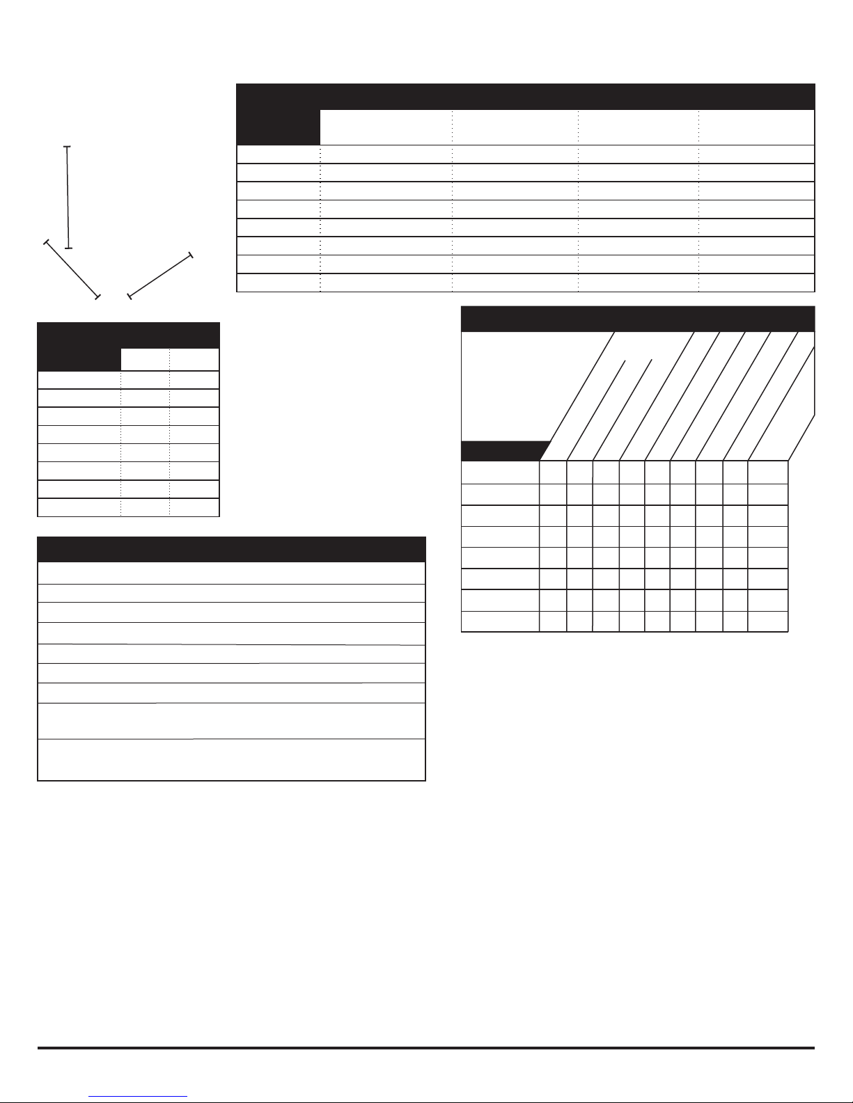
MOTOR MAKE HP RATINGS
& MODEL Pre-2007 Now
Honda GX120 4 hp 3.5 hpà
Honda GC160 5 hp 4.6 hpà
Honda GX160 5.5 hp 4.8 hpà
Honda GX200 6.5 hp 5.5 hpà
Table 2
Table 1
¸Measurement not yet available.
Patent 5,503,526
WARRANTY. VFENTRY ANS
come with lifetime factory
support. Also, workmanship
and materials are covered on
all for five years.VF
ENTRY ANS
Our customers have deemed
this our “No BS” warranty.
No matter your fan’s age or
origin, if you ever have
questions, please contact us
and we will help!
FEATURES OF ALL VENTRY FANS®
VOLUME THRUST CO FUEL RUN TIME ENGINE/MOTOR WARRANTY
MODEL TYPE PROP MOTOR/ENG. HP* (CFM) (LBS) (PPM) CAPACITY /TANK Commercial/Institutional Use
20EM3550 Electric 20 Baldor EM3550 1.5 10,500 8. 0 N/A N/A Motor 18 mos; Drive 18 mos1
®
20GX120 ®
Gas 20 Honda GX120 3.5 16,500 12.7 17 2.1 qts 1.8 hrs Engine: 3 years
20GC160 ¸Gas 20 Honda GC160 4.6 17,000 13.5 1.9 qts 1.5 hrs Engine: 3 months
20GX160 ¸Gas 20 Honda GX160 4.8 17,300 14.4 3.3 qts 2.0 hrs Engine: 3 years
24GX120 Gas 24 Honda GX120 3.5 20,000 17.6 16 2.1 qts 1.8 hrs Engine: 3 years
24GC160 Gas 24 Honda GC160 4.6 23,800 19.7 30 1.9 qts 1.5 hrs Engine: 3 months
24GX160 Gas 24 Honda GX160 4.8 24,000 19.8 32 3.3 qts 2.0 hrs Engine: 3 years
24GX200 Gas 24 Honda GX200 5.5 29,500 24.4 19 3.3 qts 1.7 hrs Engine: 3 years

Figure 3. Three
wheel choices.
20170322 Fan Specs
Small
Solid Rubber Medium
Flat-Free
Large
Pneumatic
ELECTRIC FAN MODEL 20EM3550
Table 5
Table 4
Motor: 1.5 hp / 1.1 kW
Wattage: 1800 watts
Input: Single phase, 100-115V, 50-60 Hz
Output to Motor: Three phase (lowers weight)
Amps: 15 Amp or less, even at start-up (no initial spike)
Controller: Variable speed from 0 to 3000 RPM
Listed: All electrical components are UL and CSA listed
NEMA 15A Plugs: Locking plug L5-15 (recommended) or
straight/non-locking 5-15 (by request). Advise upon order.
GFCI-compatible. Please note that older GFCI breakers may have
sensitivity conflicts with modern GFCI-compatible equipment.
H
W
D
Figure 1
VENTRY SOLUTIONS, INC. • (888)257-8967 • ventry.comPg 2 of 2
VFENTRY AN Specifications Continued
EVFLECTRIC ENTRY ANS, model 20EM3550, shown with legs retracted,
legs partially extended, and legs fully extended.
All three fans shown have optional
Small Solid Rubber
Wheels and Skids.
DIMENSIONS. Actual
measurements may vary ±1/2
inch in manufacturing. These
measurements were taken with the
fans’ legs retracted for storage, as
shown in Figure 1.
WEIGHT. Weights are of the base
model fan before adding any
accessories. “Dry” is without fuel
or oil; “Wet” is with fuel and oil.
ACCESSORIES AND SPECS. Availability varies by model as
shown in Table 6.
lEach new includes one Ultimate Door Stop.VFENTRY AN
lPoint of Entry Safety Lights, either halogen or LED, add
slightly more than 1 pound to fan weight. Lights fold
down when not in use so do not affect dimensions.
lSmall Solid Rubber Wheels include Stair Skids and a
vertical handle. Adds 6 lbs.
lMedium Flat-Free Wheels include Stair Skids and a
vertical handle. Adds 2.5 lbs to 24GX200 fans and 8.5 to
9.5 lbs. to other models.
lLarge Pneumatic Wheels include
a vertical handle. Adds 6 lbs.
~ Not available
lOptional
þlncluded
20EM3550 ~~~~~
ll lþ
20GX120 ~~~
ll lllþ
20GC160 ll lll
~~~ þ
20GX160 ~
ll lllllþ
24GX120 ~~
lll lllþ
24GC160 lll lll
~~ þ
24GX160 llllllllþ
24GX200 þþlllllll
Entry Point Halogen Light
Tachometer
Misting Ring
Ultimate Door
Stop
Small Solid Rubber
MODEL
Wheels
Medium Flat-Free
Large Pneumatics
ACCESSORIES BY MODEL
Table 6
Spark Arrester
Entry Point LED Light
MODEL DRY WET
20EM3550 78 ~
20GX120 60 64
20GC160 57 61
20GX160 66 72
24GX120 78 82
24GC160 64 68
24GX160 73 79
24GX200 88 94
WEIGHT (Lbs)
Fan with Fan with wheels, Fan with wheels, Fan with tires,
no wheels Small Solid Rubber Medium Flat-Free Large PneumaticMODEL
20EM3550 23.25 x 23.25 x 20.25 23.25 x 23.25 x 21 23.25 x 27.5 x 22.5 ~
20GX120 23.25 x 23.25 x 20.25 23.25 x 23.25 x 21 23.25 x 27.5 x 22.5 ~
20GC160 23.25 x 23.25 x 20.25 23.25 x 23.25 x 21 23.25 x 27.5 x 22.5 ~
20GX160 23.25 x 23.25 x 20.25 23.25 x 23.25 x 21 23.25 x 27.5 x 22.5 ~
24GX120 28 x 27 x 21.75 28 x 27 x 22.75 28 x 27 x 24 28 x 30 x 25.75
24GC160 28 x 27 x 21.75 28 x 27 x 22.75 28 x 27 x 24 28 x 30 x 25.75
24GX160 28 x 27 x 21.75 28 x 27 x 22.75 28 x 27 x 24 28 x 30 x 25.75
24GX200 ~ 28 x 27 x 22.75 28 x 27 x 24 28 x 30 x 25.75
DIMENSIONS (H x W x D, Inches)
Table 3

P
OSITIVE
P
RESSURE
V
ENTILATION
F
ANS
3
OUT OF THE BOX
After unpacking your fan, there are a couple of things you will need to do.
First: attach wheel option (if added) per included instructions.
Second: add fuel and oil. Oil amounts and specifications are listed in the engine manual under
servicing. All models use 0.63 quart of 10W-30 oil.
FAN TRANSPORT
One Person Carry
(Figure 4) Face the propeller, grip side handles with both hands and lift, pressing guard against
body.
Two Person Carry
(Figure 5) Left and right persons grasp corresponding side handles.
Figure 4. One Person Carry
Figure 5. Two Person Carry

V
ENTRY
S
OLUTIONS
,
I
NC
.
4
LEG ADJUSTMENT
Please note that these are just suggested ways of raising and lowering the fan. Each
firefighter finds a way to set the fan up that works best for them.
How to raise the fan with one person
Step 1: Loosen all three leg adjustment knobs.
Step 2: Rock the fan on two legs, one front and one rear allowing the other front leg to extend.
Step 3: Tighten the leg lock handle on the extended leg.
Step 4: Rock fan onto rear and extended front leg allowing the other front leg to extend.
Figure 6. Step 1 Figure 7. Step 2
Figure 8. Step 3
Figure 9. Step 4.

P
OSITIVE
P
RESSURE
V
ENTILATION
F
ANS
5
Step 5: Tighten the leg lock handle on the extended front leg.
Step 6: Rock the fan on the two extended legs while adjusting the remaining leg.
Step 7. Aim and tighten rear leg
Step 8. Start fan and check stability.
Figure 10. Step 5 Figure 11. Step 6
Figure 12. Step 7
Figure 13. Step 8

V
ENTRY
S
OLUTIONS
,
I
NC
.
6
Another method of raising the fan, one person
Step 1: Loosen all three legs adjustment knobs.
Step 2: Lift the fan into a one person carry position allowing legs to extend.
Step 3: Tighten one leg, whichever is most convenient.
Step 4: Balance the fan on the secured leg while adjusting the remaining front leg.
Step 5: Balance on front legs while aiming the fan. Tighten rear leg adjustment knobs.
Step 6: Start the fan and check stability.
How to lower the fan, one person
Step 1: Grasp handle of fan for support and loosen all leg
adjustment knobs.
Step 2: Use a rocking motion to lower the legs (Fig 20).
Step 3: Tighten all three leg adjustment knobs.
Videos showing how to extend and retract the
legs on a V
ENTRY
F
AN
can be seen on ventry.com.
Figure 14. Step 1.
Figure 16. Step 3.
Figure 15. Step 2.
Figure 17. Step 4.
Figure 18. Step 5. Figure 19. Step 6.
Figure 20. Lowering Fan

POSITIVE PRESSURE VENTILATION FANS
7
HOW TO USE POSITIVE PRESSURE VENTILATION
PPV The Basics
Positive pressure ventilation (PPV) is a powerful tool for firefighting but, like a double-edged
sword, it can cut both ways. Training and careful planning are essential if PPV is going to work
to its full potential. Remember the basic fire triangle (heat, air, fuel). PPV reduces the
temperature by displacing the hot flammable gasses, but it also provides the fire with an
abundant source of oxygen. Timing is the key: have everything ready for the initial attack
before positive pressure is used. The size-up needs to be done, incident command needs to
develop a plan which uses an aggressive initial attack, lines need to be setup and charged, and
firefighters in SBA’s need to be ready to attack the fire seat.
Use PPV to blow the heat and smoke out of the structure, then get in and put the fire out before
the increase in oxygen has a chance to let the fire flair up. Figure 21 is a simple example of the
fan's proper use.
The size-up should look for exterior signs that indicate the fire seat's probable location. Use that
information to develop an initial attack plan that ventilates by pushing the heat and combustible
gases out of the structure near the seat of the fire.
In actual practice it is not always possible to locate the seat of the fire during the initial size-up.
In such cases, we've found that using positive pressure at the most convenient point of entry and
venting on the opposite end of the structure works well. If possible, take into consideration
which way the atmospheric wind is blowing, especially a strong wind, because working with the
wind is more effective than trying to overpower it.
After the initial attack, positive pressure can be used to minimize smoke damage. Pressurize the
structure starting at an upwind room. Open a window and let the room completely clear of
smoke. Then close the window and entrance to that room. Proceed in a downwind direction to
clear the rest of the rooms in the structure. The downwind technique prevents smoke from
leaking back into rooms that have already been cleared and allows you to check for other fire
seats; if an upwind room refills with smoke, you've got another fire seat to deal with.
Figure 21. Proper Fan Operation
RIGHT!

VENTRY SOLUTIONS,INC.
8
Placement
Avoid operating the fan too close to a structure's
opening. Position the fan 8 to 15 feet from an
average 3' x 7' door. It is best to err on the side of
placing the fan too far from the door to prevent the
situation shown in Figure 22. Sufficient air volume
is needed to achieve positive pressure
ventilation even without a perfect door seal.
If the fan is properly positioned to optimize
positive pressure ventilation, access to the
structure will not be restricted.
Smoke Ejection
VENTRY FANS are designed to push air, as used for
positive pressure ventilation techniques. It is not
designed to handle the environment in which a
smoke ejection fan operates, where air is pulled out
of the structure (Figure 23). The propeller, gas tank
and many components of the engine are made out of
materials that will not withstand high temperatures.
If the fan is used as a smoke ejector,
damage will not be covered by the
manufacturer's warranty.
FAN SAFETY
Many years of research and development have gone
into creating VENTRY FANS. Still, if used
incorrectly, the fan can be detrimental to the operation of a fire scene. Our experience shows the
following techniques to be helpful in preventing unnecessary damage to the structure or injury to
fire fighters. Always remember that ACTUAL FIRE SCENES VARY DRASTICALLY WITH
EACH SITUATION so the ideas and techniques presented here are not always practical and may
need to be modified to fit a specific situation.
Safety Guidelines
First, stop and think! What is going on here? What effect will this have? Each individual fire
scene presents special problems that can't be anticipated in advance.
Second, fire fighters should enter the structure from where the fan is set up so they follow the
fresh air into the structure. This procedure allows the initial attack team to find victims or start
extinguishing the fire. Do not set up the fan in a manner that will blow fire onto the fire fighters.
Remember, have the wind at your back.
Third, position the fan so that it blows the fire back on itself and out of the structure rather than
into unaffected areas of the structure. For example, if the fire started burning near the front door,
set the fan up at a back door to blow the fire out the front door rather than all the way through the
structure.
Fourth, open a minimum of windows and doors for ventilation. Having too many vents open
will reduce the pressure inside the house and make positive pressure ventilation less effective.
Figure 22. Fan too Close to the Door
WRONG!
Figure 23. Never Use as a Smoke Ejector
WRONG!

POSITIVE PRESSURE VENTILATION FANS
9
The air will take the path of least resistance. If you have a lot of windows and doors open the air
will most likely take a path that isn’t the one you want to remove the smoke.
Ground Debris Pickup / Maximum Air Volume
VENTRY FANS are designed to run with the legs partially extended. By extending the legs a
minimum of six (6) inches, two important things are accomplished. First, running the fan with
the legs extended eliminates ground debris pickup and ejection which causes propeller damage.
Second, the efficiency (air volume) is increased. Operating the fan close to the ground can
reduce the air volume significantly. Raising the fan allows it to draw air from completely around
the guard, rather than trying to "suck air out of the ground".
Ideally you raise the fan all of the way. This maximizes the fan performance and makes it easier
to start. With the controls up where they are easy to reach firefighter doesn’t have to bend way
over or kneel to start the fan, minimizing firefighter fatigue.
Stability
After placing the fan in the desired position, check the fan's stability. Start the fan while
stabilizing it with one hand. Open the throttle all the way and rock the fan from side to side.
This will let you determine how stable the fan is. If necessary, adjust leg lengths to achieve a
stable position. At this time, inspect the placement of the VENTRY FAN and confirm that it is not
walking. Some wooden decks and stairways will vibrate and cause the fan to walk. A simple
change of the throttle setting can eliminate this problem. Decreasing the throttle also works on
slick surfaces.
Filling the Gas Tank
Never fill the gas tank with the fan in operation. Turn off the engine and allow it to cool before
refueling. A small spill or miscalculation while filling a running fan can introduce gas into the
air stream causing a cloud of vaporized fuel to enter a burning structure. Your imagination can
picture the result.
Backdraft Situations
Alternate ventilation techniques are necessary in the case of a backdraft situation, in which the
use of a VENTRY FAN is not recommended. After the backdraft situation has been rectified, the
VENTRY FAN can be used.

VENTRY SOLUTIONS,INC.
10
COMMON QUESTIONS ABOUT POSITIVE PRESSURE
Why positive instead of negative pressure ventilation?
Stand on the suction side of a fan -- there's not much happening. Now stand downwind and note
the difference. The same thing happens in a structure just as dramatically: with positive
pressure, smoke and heat come blasting out of the structure and visibility improves in a matter of
seconds. Additionally, positive pressure is much faster to set up. Since a VENTRY FAN sits 8' to
15' from the entrance point, unlike a negative pressure set-up, it doesn't block access points.
When should positive pressure not be used?
Never use positive pressure ventilation when a victim is hanging out of a window. The use of
positive pressure ventilation could push hot gases out of that window placing them in an
environment that could do great harm.
Never use positive pressure ventilation in a back draft situation since that condition involves
super-heated gases that will ignite explosively when oxygen is introduced. Some of the warning
signs are dark puffing smoke, heavy soot on windows and rapid air intake when an opening is
made. Beware of tight structures for possible back draft!
What is the door seal and how important is it?
Proper fan placement lets the VENTRY FAN'S cone of air cover the entry opening so that air
doesn't leak out of the opening. This provides a seal and delivers the most pressure and air
volume to the structure. Experience has taught us that a high output fan, such as a VENTRY FAN,
puts out enough air that a perfect seal is not very important. On an air-tight structure, a tight seal
is actually impossible to establish since the air forced into the structure has to come out
somewhere. An effective technique on large structures, where a lot of air is needed, involves
using at least two fans set up side-by-side.
A useful training exercise involves taping toilet paper around a door opening and then locating
the fan in such a fashion that all the toilet paper blows into the structure. Note: don't
overemphasize the importance of creating a perfect air seal on every fire scene; there are a lot
more important things to worry about in real situations.
What are some examples of positive pressure ventilation?
Occasionally, our fire department will respond to a call such as some innocent homeowner who
has just emptied his stove's ashes into a plastic bucket without realizing they were still hot. In a
situation like this, the fan gets rid of the accumulated smoke fast so we can determine its source.
The fan becomes a good public relations tool because we've cleared the smoke and located the
problem quickly. Since these fires usually occur late in the evening, we're happy to get back to
bed promptly with a minimum of excitement.
Another favorite of ours is a smoldering attic fire caused by a faulty chimney or the old dime-
behind-a-fuse trick. Without creating a vent opening, we use the fan to pressurize the house.
Enough air will leak into the attic to clear the smoke so that we can locate the individual curls of
smoke that mark the hot spots. We then use a bucket to scoop up the smoldering insulation
thereby avoiding any water damage.

POSITIVE PRESSURE VENTILATION FANS
11
Positive pressure is also very useful to pressurize areas of a structure to prevent or slow down
fire spread into uninvolved areas. We stopped a fire in a 6 unit apartment building using this
technique with three fans pressurizing the central foyer. We just opened the door to the
apartments that we wanted pressurized.
The heavy, smoldering smoke that usually accompanies pack rat conditions just begs for positive
pressure; the smoke must be cleared or it will take forever to find the fire seat.
Recently we ran mutual aid to a cabin roof fire. The roof was constructed using plank and beam
techniques. Fire had followed the cracks between the planks and could be seen from inside the
cabin. We pressurized the cabin enough that the water we sprayed on the roof didn't come
through the seams in the ceiling; we watched the water pour into the burning seams and get
blown right back out by the escaping pressurized air. The house incurred no water damage even
though the roof had started to burn through!
These stories illustrate situations in which positive pressure ventilation has been used
successfully. With a little imagination and training, your department is sure to discover many
more creative uses. Good luck, and remember, luck favors a prepared mind!
FAN COMPARISON METHODS
Ribbon Test
Several departments have described a simple test that you can use to compare the output of two
fans. These departments took two blowing fans and aimed them at each other, approximately 12
feet apart. A ribbon was held half-way between to determine which way the air was blowing.
Volume Test
We found a culvert 4 feet in diameter. A fan was placed far enough away from the opening of
the culvert to obtain a complete air seal. We then released soap bubbles into the air stream
moving through the culvert and timed how long the bubbles (air) took to pass completely
through the culvert. We could then calculate the volume of air flow that the fan produced. This
analytical technique has allowed us to optimize the propeller design so that the maximum
amount of air is moved.
Thrust Test
Basic physics states “For every action there is an equal but opposite reaction”. It follows that
measuring thrust is an easy way to compare fan performance.
You will need a flat board strong enough to hold the fan. You will also need two dowels (any
long rounded pole--even broomsticks will do.) You will also need a fish scale, preferably digital,
with which to measure thrust.
Find a smooth surface, like a shop floor or a concrete ramp, with lots of room around it. Place
the two dowels on the surface parallel to each other. Upon these, place the flat board. Check to
make sure that the board roles freely. Place the fan on the board. Attach one end of the fish
scale to the front of the fan or the board near the front of the fan and the other end attach to a
stationary object on the ground. What this accomplishes is that when the fan is started up, the
fan and the board will try to roll backwards, pulling on the fish scale. The thrust of the fan will
be what the fish scale is measuring.

VENTRY SOLUTIONS,INC.
12
WARRANTY
Propeller / Frame / Guard
Five years on workmanship and materials plus Lifetime Factory Support. Prop erosion caused
by operation of a fan over loose materials without elevating the fan high enough to avoid picking
up loose materials is not covered under warranty
Engine
For the engine manufacturer's warranty, see engine manual. Contact your local Honda or Baldor
dealer for further details.
MAINTENANCE
Engine Maintenance
Refer to the engine manufacturer's manual.
Kevlar & Fiberglass-Coated Propeller
Propellers coated with Kevlar and Fiberglass are extremely resistant to wear and tear, and require
little to no maintenance other than occasional cleaning to maintain balance. Some wear of the
paint on the leading edge should be expected. If touch-up painting is required, use a white
polyurethane enamel. Be sure to balance the propeller before placing it back on the fan to ensure
that the fan does not walk. Significant damage which penetrates the fiberglass/Kevlar coating
may require evaluation by Ventry Solutions.
Frame Maintenance
Wipe down the frame to remove dirt and grease buildup
The rubber leg ends (feet) will need to be inspected for wear. Damage such as missing pieces
may allow the fan to walk. Replacements may be obtained through Ventry Solutions or at a local
medical supply outlet.
Tachometer
Refer to the Tiny-Tach literature that came with the fan for general information. For installation
refer to the diagram on page 19.
TROUBLE SHOOTING
Fan walks during operation
Worn out Rubber Leg Ends: Look to see if the leg ends are worn out. If they have a lot of
wear you may be able to rotate them on the end of the legs. This will place a new section of
rubber into service. Otherwise give us a call for a new pair or you can pick up a new set at your
local medical supply outlet.
Out-of-Balance Propeller: An imbalance in the propeller can be caused by impact or by
abrasion. Light abrasion is considered normal wear and can be repaired by light sanding and re-
painting. Propeller balance can be checked by inserting a 5/16 inch steel rod through the
propeller center hole. Roll the rod across two level parallel edges. Make sure that there is no
breeze present while doing this procedure. The light portion of the propeller will rotate to the
top. This can be a tip, side or anywhere in-between. Add paint to the light portion or sand the
heavy portion to balance the propeller. If you have problems, contract Ventry Solutions.

POSITIVE PRESSURE VENTILATION FANS
13
Bent Frame: VENTRY FANS are by no means symmetrical. If you position yourself behind the
fan on its right side, the closest leg should be angled several degrees ahead of the left leg. This
same leg also leans out more than the left leg does. These are design aspects engineered into the
fan to increase the stability and to prevent walking. Figure 1 gives you an idea of how it should
look. If the legs do not resemble the picture, the frame or leg may be bent and will need to be
straightened or replaced.
Operating Surface: Some surfaces such as wooden decks or stairways vibrate causing the fan
to walk. Adjusting the throttle will sometimes eliminate this problem. Some fans will move
backwards if placed on extremely smooth surfaces. Because the fan produces up to 17 pounds of
thrust, surface friction may not be great enough to keep the fan stationary. In this case, reduce
the throttle until the fan quits moving.
Leg movement obstructed
If a front or rear leg sticks, several things may be occurring. First, check to see that the leg
adjustment handles are completely loosened. If this is not the problem, remove the crutch tip and
roll pin, then remove the leg from the frame. Then file the inside of the frame where the
adjustment handles are inserted. Also check around the top of the frame to see if obstructions are
present. Remove any dirt and grease that might be clogging the frame. On rear legs, the top leg
hole may require a light filing to remove any roughness. If a leg is still not sliding freely, check
the frame and leg for any abnormal bends. Replacement may be necessary.
Fan too large to fit compartment
Contact Ventry Solutions, Inc. for possible solutions.
PARTS ORDERS
This is the information we need to make sure that we get correct parts for your fan.
Fan#: ___________________________________________
Engine Serial #: ___________________________________
Options: _________________________________________
We keep a record of each fan we sell. To help us give you the best service and send the correct
parts, should they be needed, please register your VENTRY FAN. A registration form was included
in the packet with your new VENTRY FAN or you can simply call us and we will enter the
information into our system. There are many good reasons to register your products, including
that it helps ensure you receive all applicable free upgrades and that you can be reached in case
of a recall or other safety concern.

VENTRY SOLUTIONS,INC.
14
All nuts, bolts and washers are grade 5 or 8, national fine, zinc coated or better.
PARTS LIST FOR 20-INCH FRAME
Reference Part
Number Number Quantity
01 F-1009 Leg cap, ¾-inch .......................................................................................... 3
02 F-1004S 20-inch Leg, rear ......................................................................................... 1
03 F-1001A 20-inch Frame without wheel option .......................................................... 1
07 F-1010 Short foam handle ....................................................................................... 2
08 F-1018 7/8 Round cap ............................................................................................. 2
09 F-1012 20-inch “seven” handle, left ........................................................................ 1
10 942SB Rubber leg ends (feet) ................................................................................. 3
13 F-1008 Roll pins, 1¼-inch x 3/16-inch.................................................................... 6
14 F-1007 Leg adjustment handles ............................................................................... 3
15 F-1006 Leg adjustment springs ............................................................................... 3
16 F-1013 20-inch “seven” handle, right...................................................................... 1
17 F-1002S 20-inch Leg, left (when looking at front of the fan) .................................... 1
18 F-1003S 20-inch Leg, right (when looking at front of the fan) ................................. 1
19 F-1019 Motor mount bolts front with washers and nuts .......................................... 2
20 F-1020 Motor mount bolts rear with washers and nuts ........................................... 2
21 G-1024 Guard mount bracket aluminum ................................................................. 1
22 F-94225 Flat socket cap screw .................................................................................. 1
23 F-1005 Long foam handle ....................................................................................... 1
24 F-7N04C Tubing nut ................................................................................................... 1
PARTS LIST, 20 INCH-FRAME WITH WHEEL AND HANDLE OPTION
Reference Part
Number Number Quantity
01 F-1009 Leg cap, ¾-inch .......................................................................................... 6
02 F-1004S 20-inch Leg, rear ......................................................................................... 1
04 F-33827 Hand activated plunger ............................................................................... 1
05 F-1021 Towing handle lock nut, washer & spring .................................................. 1
06 F-1022 Towing handle ............................................................................................ 1
07 F-1010 Short foam handle ....................................................................................... 5
08 F-1018 7/8 Round cap ............................................................................................. 4
09 F-1012 20-inch “seven” handle, left ........................................................................ 1
10 942SB Rubber leg ends (feet) ................................................................................. 3
11 F-1023 5/16 Wheel mounting hardware (bolts, washers, nuts) ............................... 2
12 W-2001 Solid Rubber Wheels & Skids .................................................................... 2
12 MFF Medium Flat-Free Wheels & Skids ............................................................ 2
13 F-1008 Roll pins, 1¼-inch x 3/16-inch.................................................................... 6
14 F-1007 Leg adjustment handles ............................................................................... 3
15 F-1006 Leg adjustment springs ............................................................................... 3
16 F-1013 20-inch “seven” handle, right...................................................................... 1
17 F-1002S 20-inch Leg, left (when looking at front of the fan) .................................... 1
18 F-1003S 20-inch Leg, right (when looking at front of the fan) ................................. 1
19 F-1019 Motor mount bolts front with washers and nuts .......................................... 2
20 F-1020 Motor mount bolts rear with washers and nuts ........................................... 2
21 G-1024 Guard mount bracket aluminum ................................................................. 1
22 F-94225 Flat socket cap screw .................................................................................. 1
24 F-7N04C Tubing nut ................................................................................................... 1
25 F-1001W 20-inch frame with wheel option ................................................................ 1

POSITIVE PRESSURE VENTILATION FANS
15
20 Inch Frame Assembly Diagram
Other manuals for 20EM3550
1
This manual suits for next models
7
Table of contents
Other Ventry Fan manuals
Popular Fan manuals by other brands

Mercury
Mercury 450.050UK user manual

Casablanca
Casablanca M8503-01 user manual

Hinkley
Hinkley HOVER FLUSH instruction manual

Bovie
Bovie Smoke Shark III Operator's manual

Monte Carlo Fan Company
Monte Carlo Fan Company 5HVDC52D Series Owner's guide and installation manual

HKBN
HKBN Momax UItra-Air Plus Iot AP7S user guide

Cumberland
Cumberland G50CBF16GA Installation and operation manual

RITE-HITE
RITE-HITE Rave Installation and owner's manual

MAGNOVENT
MAGNOVENT AE2+ installation manual

Ruck
Ruck DVNI...D.F4 Series Installation, operating and maintenance instructions

Honeywell
Honeywell Bonterra user guide

RL
RL R627431 Series manual