Ventry POSITIVE PRESSURE VENTILATION FANS User manual

OWNER’S MANUAL
POSITIVE PRESSURE VENTILATION FANS
By Ventry Solutions, Inc.

FOR POSITIVE PRESSURE ATTACK AND VENTILATION
BY
Ventry Solutions, Inc.
Formerly J. Neils Enterprises, Inc.
14128 N. Hauser Lake Road
Hauser, ID 83854
(888) 257-8967 • (208) 773-1194
Fax: (208) 777-0360
Thank you for purchasing a VENTRY®Positive Pressure Ventilation Fan made by
Ventry Solutions, Inc. Our experience as volunteer fire fighters, coupled with feedback from fire
fighters across the country, has helped make this fan the best on the market. If you have any
comments, ideas, observations or creative uses, please contact us by phone, email, mail or fax so
that we may continue to improve our product.
Fan Serial Number:________________________________________________
Fan Size/Model: __________________________________________________
Engine Serial Number: _____________________________________________
Invoice Number: __________________________________________________
Invoice Date:_____________________________________________________
Patent 5,503,526
Copyright 2010 Ventry Solutions, Inc., Fifth Edition
Printed February 12, 2010

ii
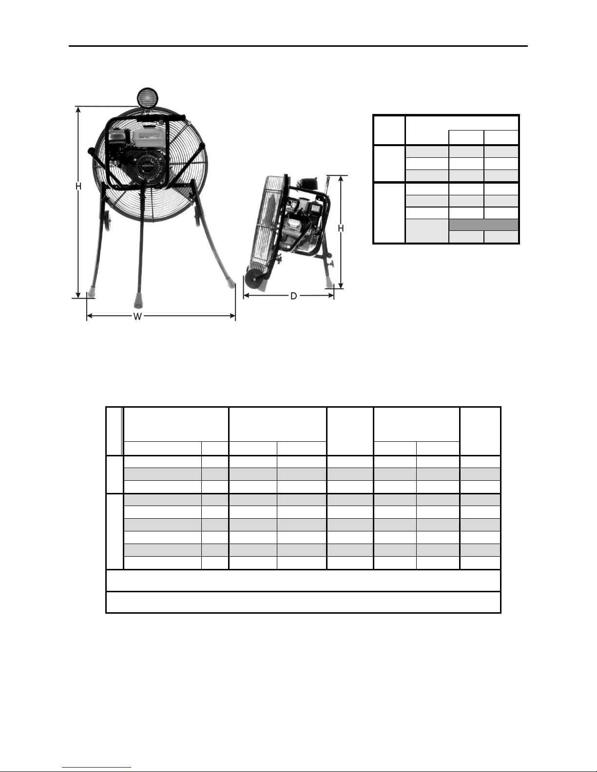
FAN SPECIFICATIONS..................................................................................................1
ADVANTAGES OF VENTRY®ALL TERRAIN FANS......................................................2
OUT OF THE BOX..........................................................................................................3
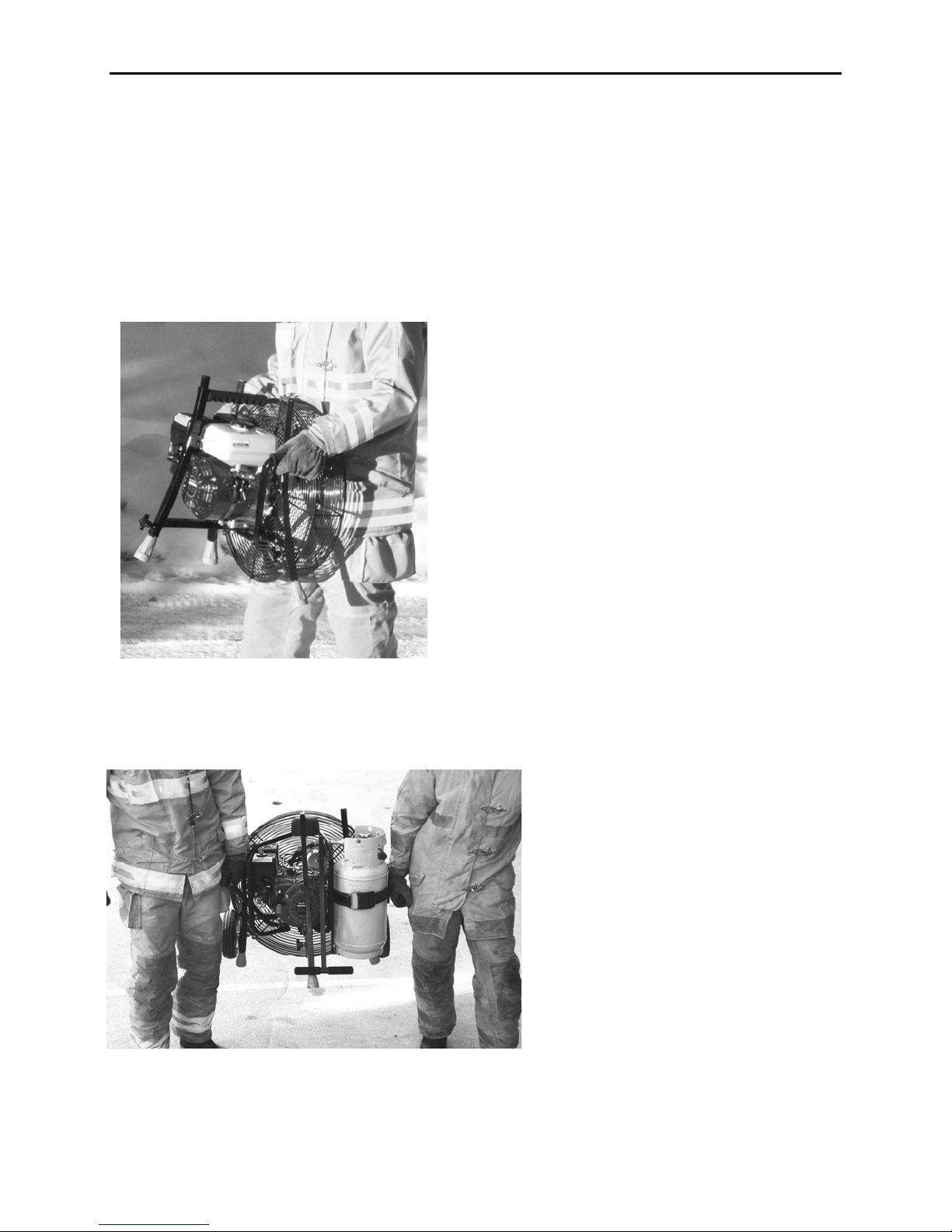
FAN TRANSPORT.......................................................................................................... 3
One Person Carry.......................................................................................................3
Two Person Carry.......................................................................................................3
LEG ADJUSTMENT........................................................................................................ 4
How to raise the fan with one person..........................................................................4
Another method of raising the fan, one person...........................................................6
How to lower the fan, one person ...............................................................................6
HOW TO USE POSITIVE PRESSURE VENTILATION................................................... 7
PPV The Basics..........................................................................................................7
Placement................................................................................................................... 8
Smoke Ejection...........................................................................................................8
FAN SAFETY.................................................................................................................. 8
Safety Guidelines........................................................................................................8
Ground Debris Pickup / Maximum Air Volume............................................................9
Stability .......................................................................................................................9
Filling the Gas Tank.................................................................................................... 9
Backdraft Situations.................................................................................................... 9
COMMON QUESTIONS ABOUT POSITIVE PRESSURE............................................ 10
Why positive instead of negative pressure ventilation?.............................................10
When should positive pressure not be used? ...........................................................10
What is the door seal and how important is it?.......................................................... 10
What are some examples of positive pressure ventilation? ...................................... 10
FAN COMPARISON METHODS................................................................................... 11
Ribbon Test............................................................................................................... 11
Volume Test..............................................................................................................11
Thrust Test................................................................................................................11
WARRANTY..................................................................................................................12
Propeller / Frame / Guard ......................................................................................... 12
Engine.......................................................................................................................12
TABLE OF CONTENTS

iii
MAINTENANCE............................................................................................................ 12
Engine Maintenance................................................................................................. 12
Kevlar & Fiberglass-Coated Propeller....................................................................... 12
Frame Maintenance.................................................................................................. 12
Tachometer............................................................................................................... 12
TROUBLE SHOOTING.................................................................................................12
Fan walks during operation....................................................................................... 12
Leg movement obstructed.........................................................................................13
Fan too large to fit compartment...............................................................................13
PARTS ORDERS..........................................................................................................13
PARTS LIST FOR 20 INCH FRAME............................................................................. 14
PARTS LIST, 20 INCH FRAME WITH WHEEL AND HANDLE OPTION...................... 14
20 Inch Frame Assembly Diagram............................................................................ 15
PARTS LIST 24 INCH FRAME ..................................................................................... 16
PARTS LIST, 24 INCH FRAME WITH WHEEL AND HANDLE OPTION...................... 16
24 Inch Frame Assembly Diagram............................................................................ 17
PARTS LIST FOR ENGINE, TACH AND SPARK......................................................... 18
Spark Arrester and Stickers GX Series Engines....................................................... 18
Spark Arrester and Stickers Honda GC135 Engine.................................................. 18
Tachometer/Hour Meter............................................................................................ 19
PARTS LIST FOR GUARD MOUNT............................................................................. 20
Guard Mount Pictures............................................................................................... 21
PROPELLER ORIENTATION.......................................................................................22
PARTS LIST FOR PROPELLER MOUNT.....................................................................22
Propeller Hubs and Tab Washer Pictures................................................................. 23
PARTS LIST FOR FRONT OF GUARD........................................................................ 24
Guard Front Picture ..................................................................................................24
PARTS LIST FOR LIGHT OPTION............................................................................... 25
Light Option Pictures.................................................................................................25
TORQUE VALUES........................................................................................................ 26


POSITIVE PRESSURE VENTILATION FANS
1
FAN SPECIFICATIONS
Note the asymmetrical appearance of the fan, both from the front and the side. These are design
aspects that keep the fan from walking.
Figure 1. Fan Dimensions
Fan Dimensions Inches
Size
1Ext 2Rtd
20 Depth 31½ 21¼
Inch Width 32½ 23¼
Fan Height 38½ 23¼
Depth 35½ 22¼
24 Width 36 27½
Inch Height 43½ 28¼
Fan Depth
Kohler 37¾ 24½
1Ext = fan with extended legs
2Rtd. = fan with retracted legs
Motor Size
Volume
(CFM)
Thrust
(Lbs)
Weight
(Lbs)
CO
(PPM)
Brand HP
Extended Retracted Dry Wet
20 Inch
Honda GX120 4 16500 16100 12.7 55 61 17
Honda GC135 4 16500 16400 12.7 54 59 26
Briggs Koolbore 3.5 12500 11900 12.3 50 55 22
24 Inch
Honda GX200 6.5 29500 27800 24.4 78 85 19
Kohler Made USA 6 25000 24400 21.9 77 83 --
Honda GX160 5.5 24000 23600 19.8 68 76 32
Honda GX120 4 20000 19600 17.6 62 68 16
Honda GC135 4 20000 19600 17.6 61 66 25
Briggs Koolbore 3.5 15000 14800 13.8 58 63 23
Light Option can be added to the Honda GX120 and Honda GX160 Motors
Tachometer and or spark arrester can be added to any fan.
Solid rubber wheels and handle option adds 2.5 lbs to weight with no change in size
Pneumatic tires & handle option adds 7 lbs to weight, 5 in to width, 2 in to depth, & 2 in to height.
Figure 2.Table of Fan Specifications

VENTRY SOLUTIONS,INC.
2
ADVANTAGES OF VENTRY®ALL TERRAIN FANS
Elevates air stream over obstacles and into elevated or awkward openings
Straddles obstacles, stands securely on uneven ground such as stairs and minimizes "walking"
Allows maximum flexibility in aiming air stream up and down at steep angles
CO levels well below the 35 PPM warning levels
Legs operate throughout full range of extension yet retract to fit a small compartment
Narrow air cone allows fan placement further from the structure opening to permit easy access
Efficient prop design allows for maximum air volume and quiet operation
Simple design for easy field service and next day factory parts availability
Five-year warranty on all materials and workmanship
Figure 3. Independently Extendable Legs

P
OSITIVE
P
RESSURE
V
ENTILATION
F
ANS
3
OUT OF THE BOX
After unpacking your fan there are a couple of things you will need to do.
First, add fuel and oil. Oil amounts and specifications are listed in the engine manual under
servicing. All models use 0.63 quart of 10W-30 oil.
FAN TRANSPORT
One Person Carry
(Figure 4) Face the propeller, grip side handles with both hands and lift, pressing guard against
body.
Two Person Carry
(Figure 5) Left and right persons grasp corresponding seven handles.
Figure 4. One Person Carry
Figure 5. Two Person Carry

V
ENTRY
S
OLUTIONS
,
I
NC
.
4
LEG ADJUSTMENT
Please note that these are just suggested ways of raising and lowering the fan. Each
firefighter finds a way to set the fan up that works best for them.
How to raise the fan with one person
Step 1: Loosen all three leg adjustment knobs.
Step 2: Rock the fan on two legs, one front and one rear allowing the other front leg to extend.
Step 3: Tighten the leg lock handle on
the extended leg.
Step 4: Rock fan onto rear and extended front leg allowing the other front leg to extend.
Figure 6 Step 1 Figure 7 Step 2
Figure 8 Step 3 Figure 9 Step 4.

P
OSITIVE
P
RESSURE
V
ENTILATION
F
ANS
5
Step 5: Tighten the leg lock handle on the extended front leg.
Step 6: Rock the fan on the two extended legs while adjusting the remaining leg.
Step 7. Aim and tighten rear leg
Step 8. Start fan and check stability.
Figure 10 Step 5 Figure 11 Step 6
Figure 12 Step 7 Figure 13 Step 8

V
ENTRY
S
OLUTIONS
,
I
NC
.
6
Another method of raising the fan, one person
Step 1: Loosen all three legs adjustment knobs.
Step 2: Lift the fan into a one person carry position allowing legs to extend.
Step 3: Tighten one leg, whichever is most convenient.
Step 4: Balance the fan on the secured leg while adjusting the remaining front leg.
Step 5: Balance on front legs while aiming the fan. Tighten rear leg adjustment knobs.
Step 6: Start the fan and check stability.
How to lower the fan, one person
Step 1: Grasp handle of fan for support and loosen all leg
adjustment knobs.
Step 2: Use a rocking motion to lower the legs (Fig 20).
Step 3: Tighten all three leg adjustment knobs.
Figure 14 Step 1.
Figure 16 Step 3.
Figure 15 Step 2.
Figure 17 Step 4.
Figure 19 Step 5. Figure 18 Step 6.
Figure 20 Lowering Fan

POSITIVE PRESSURE VENTILATION FANS
7
HOW TO USE POSITIVE PRESSURE VENTILATION
PPV The Basics
Positive pressure ventilation (PPV) is a powerful tool for fire fighting but, like a double-
edged sword, it can cut both ways. Training and careful planning are essential if PPV is going to
work to its full potential. Remember the basic fire triangle (heat, air, fuel). PPV reduces the
temperature by displacing the hot flammable gasses, but it also provides the fire with an
abundant source of oxygen. Timing is the key: have everything ready for the initial attack
before positive pressure is used. The size-up needs to be done, incident command needs to
develop a plan which uses an aggressive initial attack, lines need to be setup and charged, and
firefighters in SBA’s need to be ready to attack the fire seat. Use PPV to blow the heat and
smoke out of the structure, then get in and put the fire out before the increase in oxygen has a
chance to let the fire flair up. Figure 14 is a simple example of the fan's proper use.
The size-up should look for exterior signs that indicate the fire seat's probable location.
Use that information to develop an initial attack plan that ventilates by pushing the heat and
combustible gases out of the structure near the seat of the fire.
In actual practice it is not always possible to locate the seat of the fire during the initial
size-up. In such cases, we've found that using positive pressure at the most convenient point of
entry and venting on the opposite end of the structure works well. If possible, take into
consideration which way the atmospheric wind is blowing, especially a strong wind, because
working with the wind is more effective than trying to overpower it.
After the initial attack, positive pressure can be used to minimize smoke damage.
Pressurize the structure starting at an upwind room. Open a window and let the room completely
clear of smoke. Then close the window and entrance to that room. Proceed in a downwind
direction to clear the rest of the rooms in the structure. The downwind technique prevents smoke
from leaking back into rooms that have already been cleared and allows you to check for other
fire seats; if an upwind room refills with smoke, you've got another fire seat to deal with.
Figure 21. Proper Fan Operation
RIGHT!

VENTRY SOLUTIONS,INC.
8
Placement
Avoid operating the fan too close to a
structure's opening. Position the fan 8 to 15 feet
from an average 3' x 7' door. It is best to err on the
side of placing the fan too far from the door to
prevent the situation shown in Figure 22. Sufficient
air volume is produced to achieve
positive pressure ventilation even
without a perfect door seal. If the fan is
properly positioned to optimize positive pressure
ventilation, access to the structure will not be
restricted.
Smoke Ejection
The positive pressure fan is designed to push
air, as used for positive pressure ventilation
techniques. It is not designed to handle the
environment in which a smoke ejection fan operates,
where air is pulled out of the structure (Figure 16).
The propeller, gas tank and many
components of the engine are made out of
materials that will not withstand high
temperatures. If the fan is used as a smoke
ejector, damage will not be covered by the
manufacturer's warranty.
FAN SAFETY
Many years of research and development have gone into creating this piece of safety
equipment. Still, if used incorrectly, the fan can be detrimental to the operation of a fire scene.
Our experience shows the following techniques to be helpful in preventing unnecessary damage
to the structure or injury to fire fighters. Always remember that ACTUAL FIRE SCENES
VARY DRASTICALLY WITH EACH SITUATION so the ideas and techniques presented here
are not always practical and may need to be modified to fit a specific situation.
Safety Guidelines
First, stop and think! What is going on here? What effect will this have? Each
individual fire scene presents special problems that can't be anticipated in advance.
Second, fire fighters should enter the structure from where the fan is set up so they follow
the fresh air into the structure. This procedure allows the initial attack team to find victims or
start extinguishing the fire. Do not set up the fan in a manner that will blow fire onto the fire
fighters. Remember, have the wind at your back.
Third, position the fan so that it blows the fire back on itself and out of the structure
rather than into unaffected areas of the structure. For example, if the fire started burning near the
front door, set the fan up at a back door to blow the fire out the front door rather than all the way
through the structure.
Fourth, open a minimum of windows and doors for ventilation. Having too many vents
open will reduce the pressure inside the house and make positive pressure ventilation less
Figure 22. Fan too Close to the Door
WRONG!
Figure 23. Never Use as a Smoke Ejector
WRONG!

POSITIVE PRESSURE VENTILATION FANS
9
effective. The air will take the path of least resistance. If you have a lot of windows and doors
open the air will most likely take a path that isn’t the one you want to remove the smoke.
Ground Debris Pickup / Maximum Air Volume
This positive pressure fan is designed to run with the legs partially extended. By
extending the legs, two important things are accomplished. First, running the fan with the legs
extended eliminates ground debris pickup and ejection which causes propeller damage. Second,
the efficiency (air volume) is increased. Operating the fan close to the ground can reduce the air
volume significantly. Raising the fan allows it to draw air from completely around the guard,
rather than trying to "suck air out of the ground". We suggest that you raise the fan at least six
(6) inches.
Ideally you raise the fan all of the way. This maximizes the fan performance and makes
it easier to start. With the controls up where they are easy to reach firefighter doesn’t have to
bend way over or kneel to start the fan, minimizing firefighter fatigue.
Stability
After placing the fan in the desired position, check the fan's stability. Start the fan while
stabilizing it with one hand. Open the throttle all the way and rock the fan from side to side.
This will let you determine how stable the fan is. If necessary, adjust leg lengths to achieve a
stable position. At this time, inspect the placement of the positive pressure fan and confirm that
it is not walking. Some wooden decks and stairways will vibrate and cause the fan to walk. A
simple change of the throttle setting can eliminate this problem. Decreasing the throttle also
works on slick surfaces.
Filling the Gas Tank
Never fill the gas tank with the fan in operation. Turn off the engine and allow it to cool
before refueling. A small spill or miscalculation while filling a running fan can introduce gas
into the air stream causing a cloud of vaporized fuel to enter a burning structure. Your
imagination can picture the result.
Backdraft Situations
Alternate ventilation techniques are necessary in the case of a backdraft situation and the
use of a positive pressure fan is not recommended. After the backdraft situation has been
rectified the PPV can be used.

VENTRY SOLUTIONS,INC.
10
COMMON QUESTIONS ABOUT POSITIVE PRESSURE
Why positive instead of negative pressure ventilation?
Stand on the suction side of a fan -- there's not much happening. Now stand downwind
and note the difference. The same thing happens in a structure just as dramatically: with positive
pressure, smoke and heat come blasting out of the structure and visibility improves in a matter of
seconds. Additionally, positive pressure is much faster to set up. Since our positive pressure fan
sits 8' to 15' from the entrance point, unlike a negative pressure set-up, it doesn't block access
points.
When should positive pressure not be used?
Never use positive pressure ventilation when a victim is hanging out of a window. The
use of positive pressure ventilation could push hot gases out of that window placing them in an
environment that could do great harm.
Never use positive pressure ventilation in a back draft situation since that condition
involves super-heated gases that will ignite explosively when oxygen is introduced. Some of the
warning signs are dark puffing smoke, heavy soot on windows and rapid air intake when an
opening is made. Beware of tight structures for possible back draft!
What is the door seal and how important is it?
Proper fan placement lets the fan's cone of air cover the entry opening so that air doesn't
leak out of the opening. This provides a seal and delivers the most pressure and air volume to
the structure. Experience has taught us that a high output fan such as ours puts out enough air
that a perfect seal is not very important. On an air-tight structure a tight seal is actually
impossible to establish since the air forced into the structure has to come out somewhere. An
effective technique on large structures, where a lot of air is needed, involves using one fan set
back to establish a seal and one up close to increase the air volume forced into the structure. A
useful training exercise involves taping toilet paper around a door opening and then locating the
fan in such a fashion that all the toilet paper blows into the structure. Note: don't overemphasize
the importance of creating a perfect air seal on every fire scene; there are a lot more important
things to worry about in real situations.
What are some examples of positive pressure ventilation?
Occasionally, our fire department will respond to a call such as some innocent
homeowner who has just emptied his stove's ashes into a plastic bucket without realizing they
were still hot. In a situation like this, the fan gets rid of the accumulated smoke fast so we can
determine its source. The fan becomes a good public relations tool because we've cleared the
smoke and located the problem quickly. Since these fires usually occur late in the evening, we're
happy to get back to bed promptly with a minimum of excitement.
Another favorite of ours is a smoldering attic fire caused by a faulty chimney or the old
dime-behind-a-fuse trick. Without creating a vent opening, we use the fan to pressurize the
house. Enough air will leak into the attic to clear the smoke so that we can locate the individual
curls of smoke that mark the hot spots. We then use a bucket to scoop up the smoldering
insulation thereby avoiding any water damage.

POSITIVE PRESSURE VENTILATION FANS
11
Positive pressure is also very useful to pressurize areas of a structure to prevent or slow
down fire spread into uninvolved areas. We stopped a fire in a 6 unit apartment building using
this technique with three fans pressurizing the central foyer. We just opened the door to the
apartments that we wanted pressurized.
The heavy, smoldering smoke that usually accompanies pack rat conditions just begs for
positive pressure; the smoke must be cleared or it will take forever to find the fire seat.
Recently we ran mutual aid to a cabin roof fire. The roof was constructed using plank
and beam techniques. Fire had followed the cracks between the planks and could be seen from
inside the cabin. We pressurized the cabin enough that the water we sprayed on the roof didn't
come through the seams in the ceiling; we watched the water pour into the burning seams and get
blown right back out by the escaping pressurized air. The house incurred no water damage even
though the roof had started to burn through!
These stories illustrate situations in which positive pressure ventilation has been used
successfully. With a little imagination and training, your department is sure to discover many
more creative uses. Good luck, and remember, luck favors a prepared mind!
FAN COMPARISON METHODS
Ribbon Test
Several departments have described a simple test that you can use to compare the output
of two fans. These departments took two blowing fans and aimed them at each other,
approximately 12 feet apart. A ribbon was held half-way between to determine which way the
air was blowing.
Volume Test
We found a culvert 4 feet in diameter. A fan was placed far enough away from the
opening of the culvert to obtain a complete air seal. We then released soap bubbles into the air
stream moving through the culvert and timed how long the bubbles (air) took to pass completely
through the culvert. We could then calculate the volume of air flow that the fan produced. This
analytical technique has allowed us to optimize the propeller design so that the maximum
amount of air is moved.
Thrust Test
Basic physics states “For every action there is an equal but opposite reaction”. It follows
that measuring thrust is an easy way to compare fan performance.
You will need a flat board strong enough to hold the fan. You will also need two dowels
(any long rounded pole--even broomsticks will do.) You will also need a fish scale, preferably
digital, with which to measure thrust.
Find a smooth surface, like a shop floor or a concrete ramp, with lots of room around it.
Place the two dowels on the surface parallel to each other. Upon these, place the flat board.
Check to make sure that the board roles freely. Place the fan on the board. Attach one end of the
fish scale to the front of the fan or the board near the front of the fan and the other end attach to a
stationary object on the ground. What this accomplishes is that when the fan is started up, the
fan and the board will try to roll backwards, pulling on the fish scale. The thrust of the fan will
be what the fish scale is measuring.

VENTRY SOLUTIONS,INC.
12
WARRANTY
Propeller / Frame / Guard
Five years on workmanship and materials. Prop erosion caused by operation of a fan
over loose materials without elevating the fan high enough to avoid picking up loose materials is
not covered under warranty
Engine
For the engine manufacturer's warranty, see engine manual. Contact your local Honda,
Kohler or Briggs & Stratton dealer for further details.
MAINTENANCE
Engine Maintenance
Refer to the engine manufacturer's manual.
Kevlar & Fiberglass-Coated Propeller
Propellers coated with Kevlar and Fiberglass are extremely resistant to wear and tear, and
require little to no maintenance other than occasional cleaning to maintain balance. Some wear
of the paint on the leading edge should be expected. If touch-up painting is required, use a white
polyurethane enamel. Be sure to balance the propeller before placing it back on the fan to ensure
that the fan does not walk. Significant damage which penetrates the fiberglass/kevlar coating
may require evaluation and repair by Ventry Solutions.
Frame Maintenance
Wipe down the frame to remove dirt and grease buildup
The rubber leg bottoms (jumbo crutch tips) will need to be inspected for wear. Damage
such as missing pieces may allow the fan to walk. Replacements may be obtained through the
manufacturer or at a local medical supply outlet.
Tachometer
Refer to the Tiny-Tach literature that came with the fan for general information. For
installation refer to the diagram on page 19.
TROUBLE SHOOTING
Fan walks during operation
Worn out Rubber Leg Ends: Look to see if the leg ends are worn out. If they have a
lot of wear you may be able to rotate then on the end of the legs. This will place a new section of
rubber into service. Otherwise give us a call for a new pair or go down to the local pharmacy
and get a new set.
Out-of-Balance Propeller: An imbalance in the propeller can be caused by impact or by
abrasion. Light abrasion is considered normal wear and can be repaired by light sanding and re-
painting. Propeller balance can be checked by inserting a 5/16 inch steel rod through the
propeller center hole. Roll the rod across two level parallel edges. Make sure that there is no
breeze present while doing this procedure. The light portion of the propeller will rotate to the
top. This can be a tip, side or anywhere in-between. Add paint to the light portion or sand the
heavy portion to balance the propeller. If you have problems contract the manufacturer.

POSITIVE PRESSURE VENTILATION FANS
13
Bent Frame: Ventry Solutions’ positive pressure fan is by no means symmetrical. If
you position yourself behind the fan on its right side, the closest leg should be angled several
degrees ahead of the left leg. This same leg also leans out more than the left leg does. These are
design aspects engineered into the fan to increase the stability and to prevent walking. Figure 1
gives you an idea of how it should look. If the legs do not resemble the picture, the frame or leg
may be bent and will need to be straightened or replaced. Contact the manufacturer.
Operating Surface: Some surfaces such as wooden decks or stairways vibrate causing
the fan to walk. Adjusting the throttle will sometimes eliminate this problem. Some fans will
move backwards if placed on extremely smooth surfaces. Because the fan produces up to 17
pounds of thrust, surface friction may not be great enough to keep the fan stationary. In this
case, reduce the throttle until the fan quits moving.
Leg movement obstructed
If a front or rear leg sticks, several things may be occurring. First, check to see that the
leg adjustment handles are completely loosened. If this is not the problem, remove the crutch tip
and roll pin, then remove the leg from the frame. Then file the inside of the frame where the
adjustment handles are inserted. Also check around the top of the frame to see if obstructions are
present. Remove any dirt and grease that might be clogging the frame. On rear legs, the top leg
hole may require a light filing to remove any roughness. If a leg is still not sliding freely, check
the frame and leg for any abnormal bends. Replacement may be necessary.
Fan too large to fit compartment
Contact Ventry Solutions, Inc. for possible solutions.
PARTS ORDERS
This is the information we need to make sure that we get correct parts for your fan.
Fan#: ___________________________________________
Engine Serial #:___________________________________
Options:_________________________________________
We keep a record of each fan we sell. If we get this information we will make notes in our
database about your specific fan which will enable us to give you the best service in the future.

VENTRY SOLUTIONS,INC.
14
All nuts, bolts and washers are grade 5 or 8, national fine, zinc coated or better.
Replacement parts will be sent UPS 2nd Day Air unless otherwise requested.
PARTS LIST FOR 20 INCH FRAME
Reference Part
Number Number Quantity
01 F-1009 Leg cap, 3/4”............................................................................................... 3
02 F-1004S 20” Leg, rear............................................................................................... 1
03 F-1001A 20” Frame with out wheel option................................................................ 1
07 F-1010 Short foam handle....................................................................................... 2
08 F-1018 7/8 Round cap............................................................................................. 2
09 F-1012 20” “Seven” handle, left ............................................................................. 1
10 F296600 Rubber leg ends (jumbo crutch tips), 2” diameter ...................................... 3
13 F-1008 Roll pins, 1¼” x 3/16” ................................................................................ 5
14 F-1007 Leg adjustment handles............................................................................... 3
15 F-1006 Leg adjustment springs............................................................................... 3
16 F-1013 20” “Seven” handle, right........................................................................... 1
17 F-1002S 20” Leg, left (as seen from in front of the fan) ........................................... 1
18 F-1003S 20” Leg, right (as seen from in front of the fan)......................................... 1
19 F-1019 Motor mount bolts front with washers and nuts.......................................... 2
20 F-1020 Motor mount bolts rear with washers and nuts........................................... 2
21 G-1024 Guard mount bracket aluminum ................................................................. 1
22 F-94225 Flat socket cap screw.................................................................................. 1
23 F-1005 Long foam handle....................................................................................... 1
24 F-7N04C Tubing nut................................................................................................... 1
PARTS LIST, 20 INCH FRAME WITH WHEEL AND HANDLE OPTION
Reference Part
Number Number Quantity
01 F-1009 Leg cap, 3/4”............................................................................................... 6
02 F-1004S 20” Leg, rear............................................................................................... 1
04 F-33827 Hand activated plunger............................................................................... 1
05 F-1021 Towing handle lock nut, washer & spring .................................................. 1
06 F-1022 Towing handle ............................................................................................ 1
07 F-1010 Short foam handle....................................................................................... 5
08 F-1018 7/8 Round cap............................................................................................. 4
09 F-1012 20” “seven” handle, left.............................................................................. 1
10 F296600 Rubber leg ends (jumbo crutch tips), 2” diameter ...................................... 3
11 F-1023 5/16 Wheel mounting hardware (bolts, washers, nuts)............................... 2
12 F-1G339 Wheels 4 inch.............................................................................................. 2
13 F-1008 Roll pins, 1¼” x 3/16” ................................................................................ 5
14 F-1007 Leg adjustment handles............................................................................... 3
15 F-1006 Leg adjustment springs............................................................................... 3
16 F-1013 20” “Seven” handle, right........................................................................... 1
17 F-1002S 20” Leg, left (as seen from in front of the fan) ........................................... 1
18 F-1003S 20” Leg, right (as seen from in front of the fan)......................................... 1
19 F-1019 Motor mount bolts front with washers and nuts.......................................... 2
20 F-1020 Motor mount bolts rear with washers and nuts........................................... 2
21 G-1024 Guard mount bracket aluminum ................................................................. 1
22 F-94225 Flat socket cap screw.................................................................................. 1
24 F-7N04C Tubing nut................................................................................................... 1
25 F-1001W 20 Inch frame with wheel option ................................................................ 1

POSITIVE PRESSURE VENTILATION FANS
15
20 Inch Frame Assembly Diagram
Table of contents
Other Ventry Fan manuals
Popular Fan manuals by other brands

Panasonic
Panasonic Whisper-Lite FV-08VQL4 installation instructions

AREBOS
AREBOS AR-HE-TV40W user manual

Vent-Axia
Vent-Axia Centra Series Installation and wiring instructions

Field Controls
Field Controls CK-63 manual

ZIEHL-ABEGG
ZIEHL-ABEGG ECblue Assembly instructions

Field Controls
Field Controls 46107700 manual