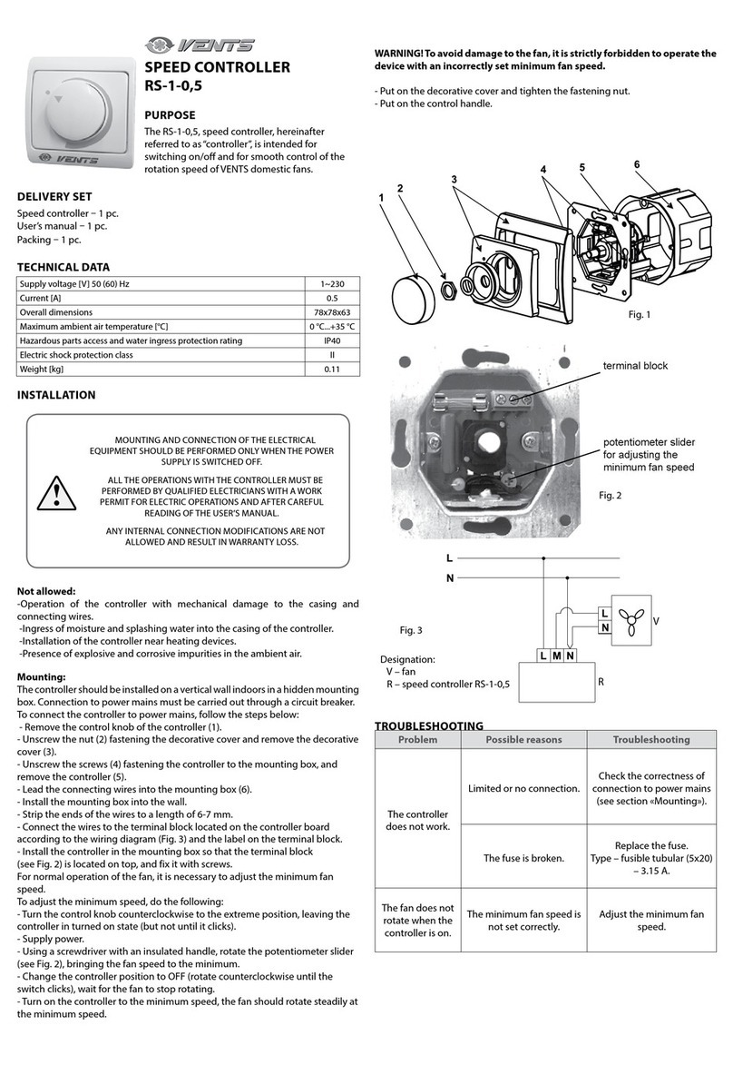
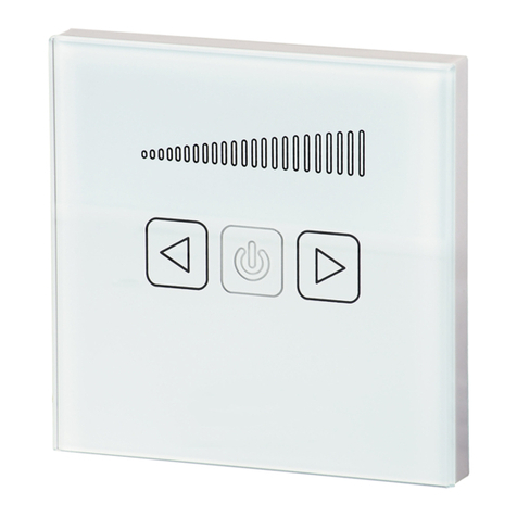
Vents RS TA Series User manual

SPEED CONTROLLER
User’s manual RS-...-TA
EN

2
EN
PURPOSE
The device is intended for use in ventilation systems for switching on/off and controlling rotation speed of single-phase
electric motors in power-controlled fans.
It is possible to control several fans if the total current consumption does not exceed the maximum allowable value of the
controller current.
DELIVERY SET
Speed controller 1 pc.
User’s manual 1 pc.
Packaging 1 pc.
Purpose..................................................................................................................................................................................................................................................... 2
Delivery set............................................................................................................................................................................................................................................. 2
Technical data....................................................................................................................................................................................................................................... 3
Design and operating principle ................................................................................................................................................................................................ 8
Mounting and set-up....................................................................................................................................................................................................................... 8
Troubleshooting.................................................................................................................................................................................................................................. 18
Storage and transportation regulations............................................................................................................................................................................... 19
CONTENTS

3
EN
TECHNICAL DATA
Main technical parameters RS-3/0-TA RS-6/0-TA RS-10/0-TA
Supply voltage [V/50 (60) Hz] ~220240
Minimum current [A] 0,3 0,5 1
Maximum current [A] 3 6 10
Fuse rating [A] F 5,0 A
H 250 VAC
F 10,0 A
H 250 VAC
F 16,0 A
H 250 VAC
Maximum ambient temperature [°С] -20 ... 40 °C at < 95% relative humidity
(without condensation)
Casing material Plastic R-ABS
Ingress Protection Rating IP54
Weight [kg] 0,84 1,0 1,08
Technical data
Analog input:
• voltage: 0-10 VDC / 10-0 VDC;
• current: 0-20 mA / 20-0 mA.
Analog input modes: acceleration or deceleration.
Analog input functionality:
Normal mode / Logic mode.
Remote control input:
Timer or Normal mode.
Adjustable output: 30–100 % Us.
Max. output load: depends on the version.
Unregulated output, L1: 230 VAC (50 / 60 Hz) / max. 2 A.
Min. output voltage, Umin: 30-70% Us (69-161 VAC),
selectable via trimmer or via Modbus.
Max. output voltage, Umax: 75-100 % Us (175-230 VAC),
selectable via trimmer or via Modbus.
The shutdown level is regulated by the trimmer:
• 0–4 VDC / 0–8 mA for the acceleration mode;
• 10-6 VDC / 20-12 mA for the deceleration mode.
Fast Start or Normal Start mode.
Low voltage output: +12 VDC / 1 mA for external
potentiometer.
Modbus RTU
Indication of operation:
• continuous green: normal operating mode;
• flashing green: in standby mode.
Excess voltage and overload protection.

4
EN
OPERATION DIAGRAM
Normal / remote operation modes
Acceleration mode Deceleration mode
Fast start of switching on
Uout, [%]
10 VDC
20 mA
Umax
Umin
0
Ai,
[VDC] /
[mA]
100
75
70
30
Umax
range
Umax
range
Uout, [%]
10 VDC
20 mA
Umax
Umin
0
100
75
70
30
Umax
range
Umax
range
Ai,
[VDC] /
[mA]
Calculation
formula for
acceleration
mode
Uout=Umin+ (Umax-min)
Ai
Aimax
Calculation
formula for
deceleration
mode
Uout=Umax- (Umax-min)
Ai
Aimax
Umax
Umin
0
Ai,
[VDC] /
[mA]
4 VDC
8 mA
U, [%] out
100
75
70
30
10 VDC
20 mA
Umax
range
Umax
range
Shutdown
level
Shutdown level
Umax
Umin
0
Ai,
[VDC] /
[mA]
10 VDC
20 mA
6 VDC
12 mA
U, [%] out
100
75
70
30
Umax
range
Umax
range
Shutdown level
The range of the
shutdown level
Smooth start of power on
Calculation
formula for
acceleration
mode
Ai-Off level
Aimax-Off level
Uout=Umin+ (Umax-min)
Calculation
formula for
deceleration
mode
Ai-Off level
Aimax-Off level
Uout=Umax- (Umax-min)

5
EN
Normal / remote operation modes
Acceleration mode Deceleration mode
Smooth start and activated
shutdown level
t, [s]
Umax
Umin
0
Uout, [%]
100
75
70
30
Umax
range
Umin
range
Duration of fast start t, [s]
Umax
Umin
0
Uout, [%]
100
75
70
30
Umax
range
Umin
range
Duration of fast start
t [s]
Umax
Umin
0
Uout, [%]
100
75
70
30
Umax
range
Umin
range
Duration of smooth start
Shutdown level
t [s]
Umax
Umin
Uout, [%]
100
75
70
30
10 VDC /
20 mA
Umax
range
Umin
range
Duration of smooth start
Shutdown level
Fast mode and activated
shutdown level

6
EN
Normal / remote operation modes
Acceleration mode Deceleration mode
Smooth start and activated level o
t [s]
Umax
Umin
0
100
75
70
30
Umax
range
Duration of smooth start
Shutdown level
Umin
range
t [s]
Umax
Umin
100
75
70
30
10 VDC /
20 mA
U
max
range
Umin
range
Duration of smooth start
Shutdown level
t, [s]
Umax
Umin
0
Uout, [%]
100
75
70
30
Duration of fast start
Umin
range
Umax
range
Ai,10 VDC / 20 mA
t, [s]
Umax
Umin
0
Uout, [%]
100
75
70
30
Umax
range
Umin
range
Duration of fast start
Fast mode and activated level o

7
EN
Timer mode Logic mode
Ai,10 VDC / 20 mA
t, [s]
Umax
Umin
0
Uout, [%]
100
75
70
30
U
max
range
U
min
range
Duration of fast start
Switch signal
0
t [s]
5 VDC
2,5 VDC
Remote
switch
VDC
Standby mode Operation
Voltage
amplitude
range
Fast start is enabled
Smooth start is enabled
t
t
t
t
SW
ONON
Holding
register
18
Holding
register
21
Duration
of soft start
Duration
of soft start
Start
Оutput
Umax
Timer
Soft start
Stop
StartStop
Timer
mode
Work time
Holding
register
18
OFF OFF
Switch signal
t
t
t
t
Ai >2,4 VDC
ON ON
Holding
register
18
Holding
register
21
Holding
register
21
Duration
of soft start
Duration
of soft start
Start
Оutput
Umax
Timer
Soft start
Start
Stop
Timer
mode
Timer
mode
Holding
register
18
OFF OFF
Ai control signal

8
EN
MOUNTING AND SET-UP
The controller is intended for indoor installation.
When installing the controller ensure unobstructed recirculation of air for cooling its internal elements.
Do not install the controller above heating equipment or in areas with insufficient air convection.
ATTENTION! After transporting or storing the product at sub-zero temperatures the controller must be kept
under the specied operating conditions for at least 4 hours prior to turning it on.
Inspect the product visually to confirm absence of any damage to the controller casing.
An automatic switch built into the stationary power supply network must be installed on the external input.
Note: To disable the ON / OFF function (3.0 A version only!) connect 230 VAC supply voltage to the unregulated output (L1).
In this case, do not connect the power supply unit to L.
DESIGN AND OPERATING PRINCIPLE
Controller casing is made of non-flammable thermoplastic.
The controller is equipped with an on/off button with backlight and an operation status indicator.
Output power change from 30 to 100% is made proportionally to the control signal 0...10 V or 4-20 mA in the selected range
during configuring the controller.
The control signal type 0...10 V or 4-20 mA is selected by a switch in the controller casing.
Controlling is possible with the use of a remote control panel, e.g. the R-1/010 controller.
The minimum rotation speed value is set by a variable resistor on the control circuit board inside the controller.
The controller has an additional terminal (230 V) for connecting and controlling external equipment (for example, air damper
drives).
The input circuit of the controller is protected from voltage and current overload by a fuse.

9
EN
INSTALLATION INSTRUCTIONS
Find a flat surface for mounting (wall, panel, etc.).
Follow these steps:
1. Turn off the power.
2. Remove the front cover by removing the self-tapping screws and secure the controller to the wall or panel using screws
through holes located in the back wall of the device. Observe the correct mounting position and dimensions of the device.
(See Fig. 1: Mounting dimensions and Fig. 2: Mounting position.)
Fig. 1. Dimensions [mm] Fig. 2. Mounting position
140
102
4x
Ø
4,50
92
124
205

10
EN
3. Connect the motor / fan. The connection is made using screw terminals on the controller circuit board.
4. Connect L1 output for three-wire connection, adjustable valve, etc. (if necessary). See Fig. 3.
Figure 3. Electrical circuit diagram
Power supply
230 VAC, 50-60 Hz
Unregulated
output
230 VAC/ max 2 A
Remote
controller
Modbus
RTU
Analog output
0-10 VDC / 0-20 mA
Output power
supply
+ 12 VDC / 1mA
V
WIRING AND CONNECTING
L Supply voltage [230 VAC/50(60) Hz]
N Neutral
PE Ground terminal
L1 Unregulated output (230 V/max. 2 A)
U1, U2 Adjustable output for motor connection
SW Remote switch/timer switch
A Modbus RTU (RS485), signal A
/B Modbus RTU (RS485), /B signal
+V Power supply output +12 VDC/1 mA
Ai Analog input 0-10 V/0-20 mA (10-0 V/20-0 mA) / input in Logic mode (timer function)
GND Grounding

11
EN
5. Select the desired analog input type and mode, start mode and shutdown level using the DIP switch on the circuit board.
(See Fig. 4.).
Figure 4. Setting the DIP switch
Acceleration/deceleration
mode selection
(DIP switch, position 1) 1 2 3 4
ON — deceleration mode:
10–0 VDC / 20–0 mA
OFF — acceleration mode:
0–10 VDC / 0–20 mA
OFF level selection
(DIP switch position 2)
1 2 3 4
ON - enabled
OFF - disabled
Fast / smooth start selection
(DIP switch, position 3)
1 2 3 4
ON - fast start
OFF - smooth start
Input mode selection
(DIP switch, position 4)
1 2 3 4
ON - current mode
(0-20 mA)
OFF - voltage mode
(0-10 VDC)

12
EN
6. A network bus terminator (NBT) is used to set the device as a terminator, and by default the NBT is disabled. It is installed
manually on the pins that need to be connected (see Fig. 5). To ensure correct communication, the NBT jumper must be
activated only in two devices in the Modbus RTU network (see example 1 and example 2).
Example 1 Example 2
Figure 5. Mains bus
resistor jumper
RX
NB T
NB T
Slave 2
Master
Slave n
Slave 1
Slave 2
Slave 1
RX
NB T
NB T
Master
Slave n
ATTENTION! Network bus terminators (NBTs) must be activated in the Modbus RTU network.
ATTENTION! If an AC power supply is used with a device in a Modbus network, DO NOT connect the GND terminal to
other network devices or via a CNVT-USB-RS485 converter. This can lead to permanent damage to the communication
semiconductors and/or the computer!

13
EN
7. Connect the power supply.
8. Adjust the max. speed using the trimmer (if necessary).
The default setting is Us (230 VAC), see Fig. 6.
9. Adjust the min. speed using the trimmer (if necessary).
Default is 30 % Us (69 VAC), see Fig. 7.
10. Adjust the off level value on the trimmer (if necessary).
The default value is 0 VAC, see Fig. 8.
Fig. 6. Max. speed trimmer Fig. 7. Trimmer for min. speed Fig. 8. Trimmer for setting the o
level
11. Close the housing and secure the cover.
12. Switch on the power supply.
13. Change the factory settings to the desired ones using 3SModbus software (if necessary).

14
EN
Follow the instructions below:
1. Turn on the power.
2. Set the NBT jumper, DIP switch, max. speed trimmer, trimmer for min. speed and the off level trimmer to the desired
positions / values.
Factory settings are as follows:
• the jumper is open (the mains bus resistor jumper is disconnected);
• acceleration mode: 0–10 VDC / 0–20 mA;
• OFF level;
• fast start is disabled;
• input voltage mode (0–10 VDC);
• min. settings on the trimmer for min. speed;
• max. settings on the max. speed trimmer;
• min. setting on the off level trimmer.
3. Set the analog input signal to a maximum value of 10 VDC or 20 mA.
4. The connected motor will run at a maximum or minimum speed depending on the analog input mode (acceleration /
deceleration).
5. If shutdown level is enabled and the deceleration analog input mode is selected, the motor will stop running.
6. Set the analog input signal to the maximum value of 0 VDC or 0 mA.
7. The connected fan will run at a minimum or maximum speed depending on the analog input mode (acceleration /
deceleration).
8. If the shutdown level is enabled and the acceleration analog input mode is selected, the motor will stop running.
9. If the shutdown level and the input signal are equal to the shutdown level value, the motor speed will be minimal in the
acceleration mode or maximum in the deceleration mode.
10. If the controller does not work according to the above instructions, it is necessary to check connections and settings.

15
EN
11. Check whether both LEDs (Fig. 9) are lit after turning on the device. If lit, your device has detected a Modbus network. If
not, check the connection.
Fig. 9. Communication detection indication
ATTENTION! The status of LEDs can only be checked when power is supplied to the device. Follow all necessary safety
precautions!

16
EN
OPERATING MANUAL
Operation modes
In Modbus mode you control the following parameters: Umax, Umin, fast start / smooth start, acceleration / deceleration
and shutdown level values with Modbus registers.
In autonomous mode you control the following parameters: Umax, Umin, fast start / smooth start, acceleration /
deceleration and shutdown level values with hardware settings (DIP switch, trimmers, jumpers).
In normal mode, if the shutdown level is disabled, smooth start / fast start is performed only once after the controller is
powered up, otherwise smooth start / fast start is activated every time the controller is powered on.
When Timer mode is selected, the controller receives a pulse control signal from the remote control switch. When Logic
mode is selected, the controller receives a pulse control signal from the Ai input.
In both modes — Timer mode and Logic mode — the pulse width must exceed 30 ms, otherwise the signal will be filtered.

17
EN
LED indication on the front panel
When the green LED on the front panel (Fig. 10) is continuously lit, the controller is working in normal mode. If it flashes:
• the controller works in remote control mode, or
• the controller is turned off and the analog input signal is below the shutdown level.
Fig. 10: Indication of the operating status

18
EN
TROUBLESHOOTING
Trouble Possible reasons Troubleshooting
Device is not working.
Limited or no connection. Check the correct connection to the
electrical power mains.
The fuse has failed. Replace the fuse.
Fan is not rotating when the
controller is on.
Minimum fan rotation speed is set
incorrectly. Adjust the minimum fan rotation speed.

19
EN
STORAGE AND TRANSPORTATION REGULATIONS
• Store the unit in the manufacturer’s original packaging box in a dry closed ventilated premise with temperature range
from +5 °C to + 40 °C and relative humidity up to 70 %.
• Storage environment must not contain aggressive vapors and chemical mixtures provoking corrosion, insulation, and
sealing deformation.
• Use suitable hoist machinery for handling and storage operations to prevent possible damage to the unit.
• Follow the handling requirements applicable for the particular type of cargo.
• The unit can be carried in the original packaging by any mode of transport provided proper protection against precipitation
and mechanical damage. The unit must be transported only in the working position.
• Avoid sharp blows, scratches, or rough handling during loading and unloading.
• Prior to the initial power-up after transportation at low temperatures, allow the unit to warm up at operating temperature
for at least 3-4 hours.

V47-7EN-02
Certificate of acceptance
The unit is recognized as serviceable.
RS ____________________ TA
This manual suits for next models
3
Table of contents
Other Vents Controllers manuals
Popular Controllers manuals by other brands

Emko Elektronik A.S..
Emko Elektronik A.S.. ESM-4435 instruction manual

Ascon tecnologic
Ascon tecnologic TLK 33 operating instructions

Cooper Power Systems
Cooper Power Systems mcGraw Edison 9000 Replacement instructions

Audioplex
Audioplex LLP-1 installation manual

Asentria
Asentria Teleboss 850 user manual

RS PRO
RS PRO V10730 Instruction leaflet