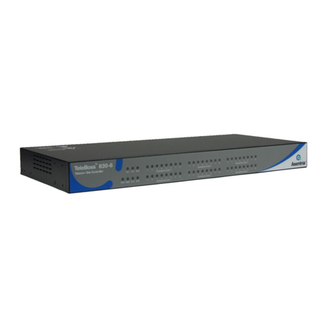
Asentria Teleboss 850 User manual

User’s Manual
Installation and Operation Guidelines
TeleBoss™ 850 Telecom Site Controller
Version 2.06.280_STD
Asentria Corporation
1200 North 96th Street
Seattle, Washington, 98103
U.S.A.
Tel: 206.344.8800
Fax: 206.344.2116
www.asentria.com

TeleBoss™ 850 Telecom Site Controller
Installation and Operation Guidelines
For firmware Version 2.06.280_STD
Manual Release Date: March 9, 2011
Manual Revision: B
Changes In This Version of the User Manual
Added new back-panel graphics and descriptions to explain the differences between the three T850 hardware
revisions.
VPN Settings command line menu removed. VPN settings can still be configured via Setting Keys and the
Web Interface pages.
Added a section about the new PPP over Serial Port feature.
Added description of the new support for SNMP v3 gets/sets with limited objects (specified in the MIB).
Added a Technical Specifications section in the Appendices.
Rev B
Removed erroneous statement that the T850 supports SFTP “gets“. It does not, only SFTP push.
Removed the description of the ’XF‘ Usage Command – thi s is not a user command.
Conventions used in this manual
Commands are printed in this format: COMMANDS (Arial font, caps, bold, black) although commands used
in the unit are not case-sensitive.
Setting Keys are printed in this format: setting.key (Courier New font, bold, blue) but any key values
displayed are in normal type.
Red type indicates a safety or security warning.
Hyperlinks to other sections in the manual are displayed in Arial font, blue, underline.
Screen shots of menus are all taken from the command line interface. Web interface shots are not displayed
in the manual at this time.
Some settings can only be changed with a Setting Key (no command line menu or web interface options).
These are noted throughout Setup Menu section of the manual by Setting Key: <name of key> with a
description of the key and allowable values.
© 2011 Asentria Corporation. All rights reserved.
The content of this manual is provided for informational use only, and is subject to change without notice. Examples,
data, and names used in this manual are examples and fictitious unless otherwise noted. No part of this document
may be reproduced or electronically transmitted without permission from Asentria Corporation.
TeleBoss 850, T850, EventSensor, SensorJack and SitePath are trademarks of Asentria Corporation.

Table of Contents
Quick Start......................................................................................................................................1
What's Included ...........................................................................................................................................................1
Hardware Needed......................................................................................................................................................1
Information Needed ...................................................................................................................................................1
Connecting...................................................................................................................................................................2
Cables and Power......................................................................................................................................................2
Power Requirements .................................................................................................................................................2
Accessing the Command Line via a Serial Connection.............................................................................................3
Accessing the Command Line via the Asentria OmniDiscover program...................................................................3
Network Setup..............................................................................................................................................................4
via OmniDiscover connection: ...................................................................................................................................4
via serial connection: .................................................................................................................................................4
Testing Network Connectivity ....................................................................................................................................4
SNMP Trap Setup ........................................................................................................................................................4
Setup..........................................................................................................................................................................4
Testing SNMP Traps..................................................................................................................................................5
What is a TeleBoss 850 .................................................................................................................6
The Basics....................................................................................................................................................................6
Communication Methods...........................................................................................................................................6
Data Storage..............................................................................................................................................................7
Remote Access..........................................................................................................................................................7
Serial Monitoring (Data Events).................................................................................................................................7
Environmental Monitoring..........................................................................................................................................7
Event Notification.......................................................................................................................................................7
Audit Log....................................................................................................................................................................7
Integration with SitePath............................................................................................................................................8
Parts Identification ......................................................................................................................................................9
Features and Accessories .........................................................................................................................................9
LEDs, Ports, DIP Switches and Buttons..................................................................................................................10
Back Panel configuration.........................................................................................................................................11
Getting Connected.......................................................................................................................14
Power Up Sequence..................................................................................................................................................14
Default Passwords ....................................................................................................................................................14
The Status Screen .....................................................................................................................................................14
Setup Menu...................................................................................................................................16
Overview.....................................................................................................................................................................16
Option Types..............................................................................................................................................................16
Web Interface.............................................................................................................................................................17
Main Setup Menu.......................................................................................................................................................17
Network Settings......................................................................................................................................................18
Serial Settings..........................................................................................................................................................31
Modem Settings.......................................................................................................................................................33
Security Settings......................................................................................................................................................36
Alarm / Event Definitions..........................................................................................................................................41
Action Definitions .....................................................................................................................................................53
General Settings ......................................................................................................................................................55
Event Log Settings...................................................................................................................................................57
Audit Log Settings....................................................................................................................................................58
Scripting Settings.....................................................................................................................................................59
Features and How To Use Them.................................................................................................60
Upgrading the T850...................................................................................................................................................60
Setting Keys...............................................................................................................................................................61
Status Keys................................................................................................................................................................62
Securing a TeleBoss 850 ..........................................................................................................................................64
NetPoll Feature........................................................................................................................................................65
Telnet/TCP Connections...........................................................................................................................................66
VLANS.........................................................................................................................................................................68

VPNs ...........................................................................................................................................................................69
VPN on-demand (VOD)...........................................................................................................................................69
Restricted trust.........................................................................................................................................................71
VPN Client ...............................................................................................................................................................73
VPN Server..............................................................................................................................................................78
Secure Shell (SSH) and Secure FTP (SFTP) ...........................................................................................................83
Configuring the SSH server for password authentication........................................................................................83
Configuring the SSH server for public key authentication .......................................................................................83
Configuring the SSH login banner ...........................................................................................................................84
How to secure SSH..................................................................................................................................................84
SFTP CDR out of the unit........................................................................................................................................84
Reestablishing authenticity of the SFTP host..........................................................................................................85
SSH to Telnet Bridging .............................................................................................................................................86
Configuration............................................................................................................................................................86
Default Router............................................................................................................................................................87
Static Routes..............................................................................................................................................................88
PPP over Serial Port..................................................................................................................................................89
IP Address Restrictions............................................................................................................................................92
IP Routing...................................................................................................................................................................93
SNMP Trap Capture...................................................................................................................................................94
SNMP Informs............................................................................................................................................................95
Configuration............................................................................................................................................................95
SNMPv3 ......................................................................................................................................................................96
Pass-through..............................................................................................................................................................97
Call Failure Tracking .................................................................................................................................................99
RADIUS Security......................................................................................................................................................100
Description.............................................................................................................................................................100
Overview................................................................................................................................................................100
Benefit....................................................................................................................................................................107
Configuration..........................................................................................................................................................107
Example.................................................................................................................................................................107
Data Events..............................................................................................................................................................109
Configuring Data Alarm Equations........................................................................................................................111
Data Alarm Macros..................................................................................................................................................112
Action List................................................................................................................................................................114
Clearing Actions in the Event Queue.....................................................................................................................116
Types of Alarm Notices...........................................................................................................................................117
SNMP Traps ..........................................................................................................................................................117
Email Alarms..........................................................................................................................................................118
Asentria Alarms......................................................................................................................................................118
SMS Alarms...........................................................................................................................................................121
Pager Alarms.........................................................................................................................................................121
EventSensor™ Configuration Setup .....................................................................................................................122
Contact Closure Setup...........................................................................................................................................122
Temperature Sensor Setup....................................................................................................................................123
Humidity Sensor Setup..........................................................................................................................................124
Analog Voltage / Current Sensor Setup.................................................................................................................125
Relay Output Setup................................................................................................................................................128
Relays as Alarm Action...........................................................................................................................................130
EventSensor Reporting...........................................................................................................................................131
SensorJack™ and EventSensor™ Setup.............................................................................................................132
Connections...........................................................................................................................................................132
Connections.............................................................................................................................................................132
DIP Switch Settings ...............................................................................................................................................133
Configuration..........................................................................................................................................................133
Calibration of Temperature and Humidity Sensors................................................................................................133
Virtual EventSensor Setup .....................................................................................................................................134
Customizable Command Prompt...........................................................................................................................135
IP Record Collection (IPRC)......................................................................................................136
Generic Server.........................................................................................................................................................136
Avaya –Reliable Session Protocol........................................................................................................................137
Alcatel OmniPCX 4400 ............................................................................................................................................138
CCM 4 (Cisco CallManager version 4.x)................................................................................................................142

Generic Client ..........................................................................................................................................................147
Siemens HiPath 4000............................................................................................................................................147
Intecom Telari ..........................................................................................................................................................148
Nortel BCM ...............................................................................................................................................................149
Syslog.......................................................................................................................................................................150
NEC NEAX2400........................................................................................................................................................152
CCM 5 (Cisco CallManager version 5.x)................................................................................................................153
Scripting .....................................................................................................................................154
Configuration...........................................................................................................................................................154
Script Management .................................................................................................................................................154
Uploading/Downloading/Deleting Scripts using the Setting Keys function............................................................156
Script Settings .........................................................................................................................................................157
Script List ...............................................................................................................................................................157
Manage Script Files ...............................................................................................................................................158
Script Programming Guide.....................................................................................................................................159
Scripting FAQ...........................................................................................................................................................159
OmniLua Function List ...........................................................................................................................................161
Command Reference.................................................................................................................188
User Interface Commands......................................................................................................................................188
Setup Commands....................................................................................................................................................188
Data Release Commands........................................................................................................................................189
System Commands .................................................................................................................................................190
Numeric Commands................................................................................................................................................191
Usage Commands ...................................................................................................................................................192
Expansion Card Insertion Procedures.....................................................................................195
Wireless Modem.........................................................................................................................196
Installation................................................................................................................................................................196
Setup.........................................................................................................................................................................196
Setting Keys...........................................................................................................................................................196
Setup Menu............................................................................................................................................................197
Operation..................................................................................................................................................................197
Status Commands .................................................................................................................................................198
Troubleshooting Commands..................................................................................................................................198
ADSL Modem..............................................................................................................................199
Installation................................................................................................................................................................199
Description of ADSL................................................................................................................................................199
Configuration...........................................................................................................................................................199
Activation .................................................................................................................................................................200
DSL Status................................................................................................................................................................202
Connectivity.............................................................................................................................................................202
Deactivation .............................................................................................................................................................202
ADSL specifications................................................................................................................................................202
DSL Routing.............................................................................................................................................................203
DSL Glossary...........................................................................................................................................................204
Battery Backup Module.............................................................................................................206
Setup.........................................................................................................................................................................206
Operation..................................................................................................................................................................206
Appendices.................................................................................................................................207
User Rights Table....................................................................................................................................................207
Control Characters..................................................................................................................................................209
Technical Specifications.........................................................................................................................................210
T850 Hardware Revisions, Sensor Ports and Sensors........................................................................................211
Rev B .....................................................................................................................................................................211
Rev D.....................................................................................................................................................................212
Rev F......................................................................................................................................................................213
Internal Modem Guidelines.....................................................................................................................................214
Canadian Department of Communications...........................................................................................................215
Warranty Information ..............................................................................................................................................217


TeleBoss 850 2.06.280_STD User Manual
Page 1
Quick Start
What's Included
This chapter is a brief guide to help get your TeleBoss 850 (T850) up and running quickly.
Hardware Needed
Asentria TeleBoss 850
15VDC power adaptor (Included if AC power option)
DC power source (if DC power option)
Computer with serial port and terminal emulation software, and/or network access.
Ethernet cable
RJ45 M-M unshielded serial cable and RJ45/DB9 straight thru adapter (Included)
A PC running any type of SNMP trap management software, if T850 will be sending SNMP traps as event actions.
Information Needed
IP address(es) to assign to the T850
Subnet mask
Default router IP or gateway router IP address if on a WAN (Optional)
IP address of a PC running any type of SNMP trap management software, if T850 will be sending SNMP traps as
event actions.
Physiclly Install TeleBoss
Note: THIS PRODUCT MUST BEINSTALLED WITHIN A RESTRICTED ACCESS LOCATION WHERE ACCESS
IS THROUGH THE USE OF A TOOL, LOCK AND KEY, OR OTHER MEANS OF SECURITY, AND IS
CONTROLLED BY THE AUTHORITY RESPONSIBLE FOR THE LOCATION.
Ensure conditions A-E will be met by the installation before proceeding.
A) Elevated Operating Ambient - If installed in a closed or multi-unit rack assembly, the operating ambient
temperature of the rack environment may be greater than room ambient. Therefore, consideration should be given to
installing the equipment in an environment compatible with the maximum ambient temperature (Tma), which is 40C
for standard units 65C for extended temperature units.
B) Reduced Air Flow- Installation of the equipment in a rack should be such that the amount of air flow required for
safe operation of the equipment is not compromised.
C) Mechanical Loading - Mounting of the equipment in the rack should be such that a hazardous condition is not
achieved due to uneven mechanical loading.
D) Circuit Overloading - Consideration should be given to the connection of the equipment to the supply circuit and
the effect that overloading of the circuits might have on overcurrent protection and supply wiring. Appropriate
consideration of equipment nameplate ratings should be used when addressing.
E) Reliable Earthing -Reliable earthing of rack-mounted equipment should be maintained. Particular attention should
be given to supply connections other than direct connections to the branch circuit (e.g.use of power strips).
Physically install the SiteBoss into your site. Use the included Mounting Brackets to secure to a standardly grounded
equipment rack.
If the unit is not mounted within a grounded rack system, connect the attached ground wire securely to an appropriate
earth ground.
Connect an Ethernet cable into the RJ45 jack labeled ETH1.

TeleBoss 850 2.06.280_STD User Manual
Page 2
Connecting
Cables and Power
1. Connect the RJ45 cable (with optional adapter, if needed) to the serial port I/O2 of the T850 and the COM1
of a PC or laptop running any terminal emulator.
2. Connect the attached ground wire securely to an appropriate earth ground (this is essential).
3. Connect an Ethernet cable, if available, into the RJ-45 jack labeled ETH1.
4. Connect the power supply to the unit (see Power Requirements section).
Power Requirements
The T850 is configured with one of two types of power connectors: AC or DC.
If configured for AC, the unit uses a barrel connector for connecting to the 15VDC power adapter shipped with the
unit.
If configured for DC, the unit is configured with a 4-pin Molex connector for use with a DC power source. The unit is
shipped with the cables and instructions for direct connection to a DC power source. The instructions are shown
below, in case they are missing from the box.
Note: This instruction sheet describes connection of the provided –48V wiring harness kit to the source power
supply. This unit should be assembled and installed by a qualified technician who can ensure the power source is an
isolated, SELV (Safety Extra Low Voltage) circuit. There are two versions of the harness using different wiring colors
as shown below.
Note: The DC input should be protected by an external 2A DC rated slow Blow Fuse suitable for branch circuit
protection, at the power supply or within the building circuitry. The input DC power current limiting fuse circuit is
provided for by the end user, and is required for unit operation in compliance with safety agency approvals.
CONTENTS:
Please inventory the package contents and ensure you have the following items pertaining to the -48VDC Power
Option:
1. A cable harness consisting of 2 red and 2 blue wires connected to a white nylon “molex” connector.
2. A bare white nylon housing.
3. 5 crimp-on contacts.
-48VDC CONNECTION:
The -48VDC power supply option has 4 input connections.
This gives the user the ability to connect this unit to an auxiliary
-48VDC power source. Note: The dark area on the diagram
represents the latching mechanism on the housing.
DANGER! FIRE HAZARD!
DO NOT LEAVE AN UNCONNECTED WIRE EXPOSED!
DO NOT CONNECT THE UNIT TO ANY OTHER EQUIPMENT UNTIL YOU KNOW THE UNIT POWERS UP
CORRECTLY!
Option A: Connect the supplied harness assembly to your -48VDC voltage source:
1. Ensure the unit is not connected to any peripheral equipment.
NOTE: Peripheral Equipment connections may cause a short circuit of your -48V supply if the power
connections are reversed! Do not connect peripheral equipment connections until you know the unit is
operational by observing the front panel Power LED.
2. Strip the ends of the wires.
-48VDC BLUE
GND RED
-48VDC BLUE
GND RED

TeleBoss 850 2.06.280_STD User Manual
Page 3
3. Using wire nuts (not supplied), connect the stripped wires to the power source. The red wires connect to ground
or the most Positive connection on the voltage source. The blue wires connect to -48VDC or the most Negative
connection on the voltage source.
Option B: Use the supplied kit to make a wire harness:
1. You will need a crimping tool that crimps standard Molex type 18-24 AWG Mini-Fit Terminals (Molex Part
Number: 39-00-0060, Engineering Series 5556).
2. Crimp the supplied terminals to your cable connections.
3. Insert the crimped terminals into the supplied white nylon housing. Orient the housing so the latching mechanism
is up and you are looking into the large end of the housing. See diagram above. Insert the 2 Ground or Most
Positive leads into the upper and lower compartments on the left side of the connector, e.g. the same positions as
the red wires on the supplied harness assembly. Insert the 2 -48VDC or Most Negative leads into the upper and
lower compartments on the right side of the connector, e.g. the same positions as the blue leads on the supplied
harness assembly.
4. Connect the completed assembly into the power input receptacle at the rear of the unit.
Accessing the Command Line via a Serial Connection
1. Connect to I/O 2 with a serial terminal emulation program at 19200 baud, 8N1.
2. Enter STATUS or ?and press <Enter>. You will be presented with a status screen similar to the following.
TeleBoss 850 2.06.280 STD - Status
Site Name : 850-850000163
Serial Number : 850000163 Eth 1 : STATIC
Date : THU 03/03/2011 IP Addr : 0.0.0.0
Time : 08:02:48 MAC Addr : 00:10:A3:60:02:3E
Memory : 32768K Eth 2 : STATIC
% Full Alarm : OFF IP Addr : 0.0.0.0
No-Data Alarm 1 : OFF MAC Addr : 00:10:A3:60:02:3F
No-Data Alarm 2 : OFF Modem : Yes
Duplex : FULL
-------------------------------------------------------------------------
Port Baud/Etc. Recs Bytes Full Wrap Name
IO1 : 19200,8N1 00000000 00000000 0% OFF I/O 1
IO2 : 19200,8N1 00000000 00000000 0% OFF I/O 2
COMPLETE
>
When the status screen appears, the unit is successfully connected and ready for use.
Accessing the Command Line via the Asentria OmniDiscover program
1. From the Asentria website (http://www.asentria.com/docsandsoftware/productManuals.aspx), or the
Documentation and Utilities CD, download the OmniDiscover program. This program will allow you to locate
devices on your network (ie: the T850) with Asentria MAC addresses, and allow you to assign the network
settings directly over the network, thus eliminating the need for the serial port connection as described above.
2. Open the OmniDiscover program. It will immediately display all Asentria devices on the network. Right clicking
on the line for this unit displays three options: Setup, Telnet and Web.
Setup opens another window where the IP Address, Subnet Mask, and Gateway (router) can be configured
(see below). Press “OK” and these will be assigned to the unit and displayed in the previous window. (Select
this option to configure the network settings for the first time.)
Telnet opens a connection to the device using your default Telnet client.

TeleBoss 850 2.06.280_STD User Manual
Page 4
Web opens an HTTP connection to the device using your default browser, if the device supports and is
configured to allow a web connection.
3. Once the network settings have been assigned, the T850 command line can be accessed via any Telnet client or
HTTP web connection.
Contact Asentria Technical Support for any questions or assistance with OmniDiscover.
Network Setup
via OmniDiscover connection:
1. See the description of how to use OmniDiscover as described above.
via serial connection:
1. Access the Main Setup Menu by typing SETUP and pressing <Enter>.
2. Select the Network Settings branch.
3. Select A) Ethernet Settings and select the Ethernet interface that corresponds to the one on the back panel that
you plugged your network cable into.
4. Enter an IP address, subnet mask and--if necessary--a router address.
5. Toggle NAT on/off as desired.
6. If using this Ethernet interface for a VLAN connection, select this option to configure any of six VLAN connections.
See the VLANs section in the Features chapter for details on how to configure.
7. Press <ESC> to go back one level in the menu tree, or <CTRL + C> to exit the Main Setup Menu and return to
the command prompt.
Testing Network Connectivity
1. Verify that the network router is available to the unit by typing the command PING <IP_address>. A router is
always a good candidate to test pings. The following screenshot is an example of a successful ping test.
ping 192.168.100.59
PING 192.168.100.59 (192.168.100.59): 56 data bytes
64 bytes from 192.168.100.59: icmp_seq=0 ttl=128 time=8.0 ms
64 bytes from 192.168.100.59: icmp_seq=1 ttl=128 time=0.7 ms
64 bytes from 192.168.100.59: icmp_seq=2 ttl=128 time=1.8 ms
64 bytes from 192.168.100.59: icmp_seq=3 ttl=128 time=0.8 ms
64 bytes from 192.168.100.59: icmp_seq=4 ttl=128 time=0.7 ms
64 bytes from 192.168.100.59: icmp_seq=5 ttl=128 time=0.7 ms
--- 192.168.100.59 ping statistics ---
6 packets transmitted, 6 packets received, 0% packet loss
round-trip min/avg/max = 0.7/1.7/8.0 ms
2. Press <CTRL + C> to stop the ping testing. If <CTRL + C> is not pressed, the unit will continue pinging attempts
indefinitely.
3. If there is an error message or no response from the router, first check the network settings and connection, then
consult your System Administrator or Asentria Technical Support.
4. Using a Telnet client, connect to the IP address assigned to the unit.
SNMP Trap Setup
If you will be using your T850 to send SNMP traps, this section will help you ensure it is set up correctly.
Setup
1. Configure the network settings as described in the previous section.
2. Select the Network Settings then SNMP Settings sub-menu.
3. Verify the SNMP Community name is correct for your network.
4. Switch to the Action Definitions menu and enter the Hostname or IP address of the computer to receive the traps
into the field, “Hostname/IP Address 1”.

TeleBoss 850 2.06.280_STD User Manual
Page 5
5. Press <CTRL + C> to exit the Setup menu and return to the command prompt.
6. On the computer that will be receiving the SNMP traps, start your preferred SNMP trap manager.
Testing SNMP Traps
1. Using a Telnet client, connect to the IP address assigned to the unit.
2. Enter the command DOTRAP from the command prompt.
3. Verify that the trap manager receives the test trap.
4. If there is an error message or no response from the router, first check the network settings and connection, then
consult your System Administrator or Asentria Technical Support.

TeleBoss 850 2.06.280_STD User Manual
Page 6
What is a TeleBoss 850
The Basics
Fig 1: TeleBoss 850-0
Note: Functionally, the TeleBoss 850-0 is identical to the T850-2 and T850-6 products, except that it does not
have expansion bays on the back panel for insertion of different I/O Expansion Cards. Therefore, references in this
manual to Expansion Cards (wireless modems, GPS) functions do not apply to the T850-0. However, the T850-0
does feature an on-board sensor port for use with Asentria EventSensors, many of which feature the same I/O as
some of the optional Expansion Cards, so references to contact closures, analog sensors, and relay outputs are all
applicable to the T850-0.
Fig 2: TeleBoss 850 (T850-2 on top, T850-6 on bottom)
The T850 is a powerful remote device management system which can collect and forward text records such as those
used by Call Accounting and Telemanagement billing applications. These records are collected by the T850 from
PBX serial ports, and in some cases directly over a TCP/IP connection. The T850 can also make a passthrough
connection directly to devices connected on one of its serial ports, and can also connect you via web or Telnet to
other devices on the same remote network as the T850. The T850 provides versatile alarm management of text-
based alarms as well as interfaces with environmental monitoring equipment and contact closure alarms at your
remote site. The T850 is a powerful remote network management solution for Call Accounting systems, Service
Bureaus, and end users who need to collect PBX data as well as get remote access, and collect alarms from
equipment at remote sites.
On-board I/O provides serial, Ethernet, and dialup connectivity. The T850-2 (11-inch) and T850-6 (17-inch)
models provide two or six expansion slots respectively to allow addition of various communications and
monitoring interfaces (Expansion Cards).
Communication Methods
The T850 has a diverse selection of communication methods available for different applications. The following
methods can be used to either access the command processor or provide a passthrough connection to devices
attached to the serial ports. All methods of connecting to the unit can be secured via password for protection of data
and hardware.
RS-232 serial
Telnet
Standard modem serial
Security callback modem serial
SSH
HTTP Server

TeleBoss 850 2.06.280_STD User Manual
Page 7
Data may be retrieved from or through the T850 by any of the following methods:
Serial or modem connection to command processor (using Line or Zmodem) or pass-through
Inline Mode (data in I/O1, data out I/O2)
Telnet to command processor or passthrough
Telnet real-time sockets
FTP or SFTP push (automatic delivery to FTP or SFTP server)
FTP get (manual retrieval from FTP server)
Alarms generated or detected within the T850 can be delivered through any of the following means:
●Modem callout ●Dialup pager ●Asentria Alarms
●SNMP trap ●Script actions ● Relays (if configured with optional relay Expansion Card)
● Email ● SMS Messages
Data Storage
Basic data storage in the T850 is accomplished in a database of four files –FILE1, FILE2, EVENTS, and AUDIT.
FILE1 and FILE2 are typically associated with Serial Port I/O 1 and Serial Port I/O 2 respectively, although either
serial port can store to either FILE1 and FILE2, or both. Data collected via IP Record Collection (IPRC) is also stored
to either FILE1 or FILE2. EVENTS and AUDIT are log files generated from the Event Log Settings and Audit Log
Settings menus per the parameters set there. The number of records stored in each these four files can be displayed
using the DIR command on any connection to the command processor, including FTP.
The T850 also features three “auxillary” files for storage of data to be used in scripting functions, named AUX1, AUX2,
and AUX3. These three files are not displayed with the DIR command, although data collected via serial port or IPRC
can be stored to any of these three auxillary files in addition to FILE1 and FILE2. Refer to the Scripting chapter for
more information on processing data stored in AUX1, AUX2 and AUX3.
Remote Access
The T850 can provide an administrator transparent access to devices connected to the serial ports of the unit via
serial, modem, and Telnet pass-through connections. This sort of access can be used to configure, maintain, or
manipulate devices that would normally have no remote access.
Serial Monitoring (Data Events)
The T850 can be used to monitor incoming data for user-defined strings and then report the event via several
avenues. The T850 allows for up to 1000 different data events. Each data event contains independent actions,
counters, and other unique settings. Data events triggered within the T850 can be logged to an Event Log. This file
can be viewed through the Event Log section of the Setup menu, via the TYPE EVENTS command, or via FTP or the
web interface.
Environmental Monitoring
Through the use of external EventSensor modules and/or internal Expansion Cards, a variety of environmental sensor
monitoring and alarming capabilities are available in the T850. Each individual sensor can be configured with
independent actions, counters and other unique settings. Sensor events triggered within the T850 can be logged to
an Event Log. This file can be viewed through the Event Log section on the Setup menu, via the TYPE EVENTS
command, or via FTP or the web interface.
Event Notification
Actions generated or detected within the T850 can be delivered through any of the following means:
●Modem callout ●Dialup pager ●Asentria Alarms
●SNMP trap ●Script actions ● Relays (if configured with optional relay Expansion Card)
● Email ● SMS Messages
Audit Log
The T850 has the capability to log many types of administrative events, from serial port handshaking alarms to login
attempts. These Audit Log entries are stored in a file and can be viewed through the Audit Log section of the Setup
menu, via the TYPE AUDIT command, or via FTP or the web interface.

TeleBoss 850 2.06.280_STD User Manual
Page 8
Integration with SitePath
Using the T850 in conjunction with Asentria’s SitePath Remote Management System, you can create secure and
controlled IP access to remote servers and appliances co-located on the same remote network as the T850. SitePath
uses an integrated SSL or IPSEC VPN implementation which simplifies otherwise complex VPN setup down to a few
easy steps, allowing users to access remote devices via the SitePath VPN Gateway. The T850 plus SitePath provide
IP routing to authorized remote network addresses, and prevents unauthorized access to any other addresses on the
remote LAN.

TeleBoss 850 2.06.280_STD User Manual
Page 9
Parts Identification
Features and Accessories
Standard Equipment
The base T850 comes with the following standard on-board equipment:
AC or DC Power Input
32MB logging database for CDR or other text records
2 –RJ45 DTE serial I/O ports
1 –RJ45 ESJ/ES sensor port for connection of Asentria EventSensors and SensorJack sensors.
2 –10/100Mb Ethernet interfaces with support for six 802.1Q VLAN interfaces on each.
1 –MMC memory I/O slot
0, 2 or 6 –Expansion Card slots
Internal lithium coin-cell type battery backup*/**
* Battery backup preserves clock operation when power is not present. Data records and settings are stored in non-
volatile memory and therefore do not require battery backup.
** CAUTION: THERE IS A RISK OF EXPLOSION IF THE BATTERY IS REPLACED BY AN INCORRECT TYPE.
DISPOSE OF USED BATTERIES ACCORDING TO THE INSTRUCTIONS. The instructions are that lithium batteries
can be recycled, and you should contact a recycling orgainization in your area for details.
In addition to the above components, the standard unit is shipped the following accessories:
This product manual on the Documentation and Software CD
RJ45 M-M unshielded serial cable and RJ45/DB9 straight thru adapter for each serial port ordered
RJ45 Ethernet cable for each Ethernet port
Power supply adapter (for AC units), or wiring harness and Molex plug (for DC units)
Options
Each of the following components is optional and may be installed on a T850:
Additional RJ45 DTE serial I/O ports in sets of 4 to total 6, 10, 14, 18, 22, or 26 ports
64MB logging database for CDR or other text records
Internal 33.6K baud, or wireless modem
Run-time battery (enables the unit to function for a period of time without power, if enabled).
Expansion Cards configured as wireless modem, ADSL modem, contact closures, analog sensors, and relays.
The T850 may come with any of the following accessories as well, depending on the configuration or order:
Modem cable for internal modem
Antenna for wireless modem Expansion Card
Serial cables and RJ45/DB9 adapters for 4-port Serial Expansion Cards

TeleBoss 850 2.06.280_STD User Manual
Page 10
LEDs, Ports, DIP Switches and Buttons
Fig 3: Front panel (T850-2)
LEDs –Front Panel
Power
The Power LED is green and has two operational states. During the boot up cycle, it will blink once every second until
the boot sequence is complete. During normal operation, it is steady on with a blink every 5 seconds.
MDM (Modem)
The MDM LED lights solid green whenever the modem is connected and blinks when the modem is dialing out.
ETH (Ethernet)
The Link LED lights solid green whenever an active Telnet or FTP connection is made to the unit.
ALM (Alarm)
This LED is reserved for future use.
25% - 75% - 100%
The T850 has three LEDs to indicate file full status. A blinking percentage full LED indicates the database has less
than the amount indicated by that LED, but more than the previous. A solid lit LED indicates the database percentage
is at or over the value for that LED.
Expansion Card n
Each optional Expansion Card has eight LEDs associated with it that may or may not be used.
LEDs –Back Panel
Each RJ45 port on the back panel has two LEDs associated with it –one on the Right of the port, one on the Left of
the port.
Ethernet Ports (ETH1 and ETH2)
●Right –Lights solid red when an Ethernet cable is connected to the port and an active Ethernet network.
The LED is off when the cable is disconnected from the network, or the Ethernet Port.
●Left –Flashes yellow/green when network data (TCP packets) is being transmitted or received across the
port. When no data is actually being transmitted/received, this LED is off.
I/O Port 1 & 2 (and any additional 4-I/O Port cards that may be installed)
●Right –Lights solid green when a correctly configured cable from another device is connected to it.
Otherwise this LED remains off. As the I/O Port receives or transmits data, this LED will flash red.
●Left –Lights solid green when power is applied to the T850, regardless of whether a cable is connected
to the I/O Port or not.

TeleBoss 850 2.06.280_STD User Manual
Page 11
Back Panel configuration
Over the course of its lifetime, the T850 has had three hardware versions, known as Rev B, Rev D, and the current
version, Rev F. The main visually identifiable difference between each version is the sensor port. Briefly, here are
the differences:
Rev B –There is no sensor port
Rev D –The sensor port is a 9-pin Mini DIN connector port
Rev F –The sensor port is an RJ45 connector port
The type of sensor port determines what type of Asentria sensors will work with the unit. A complete description and
explanation can be found in the T850 Hardware Revisions, Sensor Ports and Sensors section of this manual.
The current hardware revsion is Rev F (noted on the serial number label as H/W Rev: F.1)
Fig 4: T850 Rev F Back Panel configurations
The above drawings show the -2 and -6 models of the T850. Not shown is the -0 model which is configured
exactly like these two models except it does not feature any expansion slots, nor the bay for the optional battery
or -48VDC power.
Ports
Memory I/O
The slot labeled Memory I/O can be used for the optional external Temperature Sensor, which is a small MMC.
Eventually T850’s may also be upgraded using a MultiMedia Card (MMC) in this slot.
Sensor
The sensor port is an RJ45 connector for use with Asentria EventSensors and SensorJack sensors.
Ethernet
The Ethernet 10/100Mb interfaces are standard RJ45. Either of these standard connectors will connect the T850 to
an Ethernet hub or switch. Refer to the Telnet/TCP Connections section in the Features chapter for further
information regarding a number of different types of Telnet connection options. LEDs by each Ethernet connection on
the back panel flicker when packets are being transmitted/received on that port.

TeleBoss 850 2.06.280_STD User Manual
Page 12
Serial Ports
Each of the two (or more) serial ports is configured as a DTE port using an RJ45 connector. This is the standard
recommended pinout for EIA/TIA-561 for 8 pin RJ45 connector:
PIN1 =RI =RING INDICATOR, INPUT to the T850
PIN2 =DCD =CARRIER DETECT, INPUT to the T850
PIN3 =DTR =DATA TERMINAL READY, OUTPUT from the T850
PIN4 =SIGNAL GROUND
PIN5 =RXD =RECEIVED DATA, INPUT to the T850
PIN6 =TXD =TRANSMITTED DATA, OUTPUT from the T850
PIN7 =CTS =CLEAR TO SEND, INPUT to the T850
PIN8 =RTS =REQUEST TO SEND, OUTPUT from the T850
The DB9 female cable end which mates with the serial port connectors of connected devices will often have a pair of
screw-down cable screws. These cable screws should be used to assure a solid connection of the cable with the
device.
Default settings for the serial ports are 19200-baud, 8-bit word length, no parity, and one stop bit (19200, 8N1). Use
the internal setup menu to adjust these settings.
Internal Modem
If a dialup POTS modem is installed, an RJ11 (typical U.S. phone) connector is used. A POTS (analog) dialup phone
line is inserted into this connector. The modem installed within this unit is FCC certified. For further information,
consult the Internal Modem Guidelines appendix or the serial number label on the bottom of the T850.
CAUTION: To reduce the risk of fire, use only No. 26 AWG or larger telecommunication line cord.
ATTENTION: Pour réduire les risques d’incendie, utilizer uniquement des conducteurs de télécommunications 26 AWG au
de section supérleure.
* Expansion Card Slots
Optional Expansion Cards can be installed to expand the capabilities of the T830-2 and T830-6. Contact Asentria
Sales (sales@asentria.com) for more information on Expansion Cards.
DIP Switches
The bank of 8 DIP switches on the back panel of the T850 are used to control the baud and parity settings of I/O2, to
set the operational mode for I/O2, and to put the unit into “boot load mode” where it can be forced to load a new
application (firmware image). The following table shows how to set the various DIP switches to obtain certain
settings:
I/O 2 Baud
SW1
SW2
2400
DOWN
DOWN
9600
UP
DOWN
19200
DOWN
UP
115200
UP
UP
I/O 2 Word, Parity
SW3
8N1
DOWN
7E1
UP
I/O 2 Mode
SW4
Command Mode
DOWN
Data Mode
UP
Boot Load Mode
SW8
SW1 thru SW7
No Forced App Reload (Default)
DOWN
X (don’t care)
Forced Application Reload
UP
UP

TeleBoss 850 2.06.280_STD User Manual
Page 13
Note: Boot Load Mode can only be set by flipping ALL DIP switches to the UP position. This is not a setting that
can be configured via internal menu settings, or Setting Keys.
Note: For settings that can be set either via DIP switch, internal menu settings, or Setting Keys, the T850 always
pays attention to the last setting, regardless of how it was done. So if the internal setting for I/O 2 Port Mode is
Command, and someone flips SW4 to the UP position, the Mode is immediately set to Data.
Buttons
The only button on the T850 is the Reset button located on the back panel next to the left of serial port I/O 2. The
Reset button can be used for two different functions:
1) To reset the T850 –press the Reset button for approximately 1 second and T850 will be begin the reboot
process as described in the Power Up Sequence section on the next page.
2) To activate the Button Unlock feature which resets the username and password back to default.

TeleBoss 850 2.06.280_STD User Manual
Page 14
Getting Connected
Power Up Sequence
On startup, the T850 goes through the following boot sequence in approximately 55 seconds:
1) The power LED flashes once each second for 30 seconds.
2) The LED for Expansion Card 1 go through a 15 second flashing sequence.
3) All LED’s then go off for approximately 5 seconds.
4) Power, Modem (if installed) and Ethernet LEDs light for 5 seconds, then Modem and Ethernet go off.
5) Power LED will blink once every 5 seconds as a "heartbeat" while the T850 is powered on.
Default Passwords
The T850 uses a very flexible system for managing users, passwords, and access rights. By default, the following
fifth user profiles are enabled. Note that if a password is defined without a user name, the profile is defined just by the
user name. All of the default profiles are password-only. All passwords are masked: ********
The default settings are configured to low security for your convenience in setup. It is highly recommended that you
change these passwords and record them in a secure location.
User
Password
Login To
User1
SMDR
Command processor
User2
SUPER
Command processor
User3
ACCESS1
Passthrough/File 1
User4
ACCESS2
Passthrough/File 2
User 11
Username: admin
Password: password
Command processor
The Status Screen
The T850 Status screen is the unit's one-stop informational source. Most of the information that a user would need to
know about the unit is available through this display. This section outlines this data and highlights why it is useful.
TeleBoss 850 2.06.280 STD - Status
Site Name : 850-850000163
Serial Number : 850000163 Eth 1 : STATIC
Date : THU 03/03/2011 IP Addr : 0.0.0.0
Time : 08:02:48 MAC Addr : 00:10:A3:60:02:3E
Memory : 32768K Eth 2 : STATIC
% Full Alarm : OFF IP Addr : 0.0.0.0
No-Data Alarm 1 : OFF MAC Addr : 00:10:A3:60:02:3F
No-Data Alarm 2 : OFF Modem : Yes
Duplex : FULL
-------------------------------------------------------------------------
Port Baud/Etc. Recs Bytes Full Wrap Name
IO1 : 19200,8N1 00000000 00000000 0% OFF I/O 1
IO2 : 19200,8N1 00000000 00000000 0% OFF I/O 2
COMPLETE
>
TeleBoss 850 indicates that this product is the T850, followed by 2.06.280 STD, the currently loaded firmware
version.
Site Name is the identifier assigned to each T850 by the end user in the General Settings menu.
Serial Number is the factory-assigned, unique serial number for this T850.
Table of contents
Other Asentria Controllers manuals
Popular Controllers manuals by other brands

Regulus
Regulus TRS 5 Installation, Wiring and Operating Instructions

Mitsubishi Electric
Mitsubishi Electric MELSEC iQ-F FX5 user manual

Arrakis Systems
Arrakis Systems MARC-15 Technical manual

Trace Engineering
Trace Engineering C35 - REV B manual

Unitronics
Unitronics Vision OPLC V570-57-C30B installation guide

H3C
H3C VCF installation guide