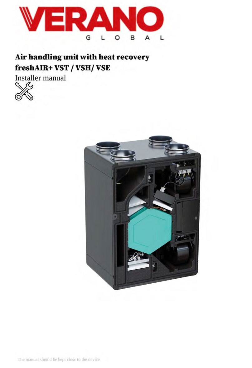
Verano freshAIR+ VWT User guide


Table of contents
1. Introduction............................................................................................................................................................................5
1.1. General information........................................................................................................................................................5
1.2. Nameplate.......................................................................................................................................................................5
1.3. Symbols...........................................................................................................................................................................5
2. Safety6
2.1. Responsibility..................................................................................................................................................................6
2.2. Protection of the environment and disposal ....................................................................................................................6
2.3. Safety rules......................................................................................................................................................................6
2.4. Safe use...........................................................................................................................................................................6
3. Product information ...............................................................................................................................................................7
3.1. Device description ..........................................................................................................................................................7
3.2. Recuperator connection sides .........................................................................................................................................7
3.3. Product overview ............................................................................................................................................................8
3.4. Product dimensions .......................................................................................................................................................9
3.5. Technical data and available variants of the device ........................................................................................................9
3.6. Transport and storage ...................................................................................................................................................10
3.7. Working conditions ......................................................................................................................................................10
3.8. The scope of basic supplies ..........................................................................................................................................10
3.9. Available accessories ....................................................................................................................................................10
4. Components used in AHUs...................................................................................................................................................11
4.1. Heat exchanger..............................................................................................................................................................11
4.2. Automatic Bypass .........................................................................................................................................................11
4.3. EC fans with Constant Flow .........................................................................................................................................11
4.4. Air filters ......................................................................................................................................................................11
4.5. PTC pre-heater .............................................................................................................................................................11
4.6. Casing made of expanded polypropylene .....................................................................................................................12
4.7. Condensate drain ..........................................................................................................................................................12
4.8. Built-in water reheater ..................................................................................................................................................12
4.9. AHU controller .............................................................................................................................................................12
5. Operating the controller........................................................................................................................................................12
5.1. User menu – structure....................................................................................................................................................12
5.2. The controller control....................................................................................................................................................13
Panel ecoTOUCH T4_RT:...............................................................................................................................................13
Panel simTOUCH2:........................................................................................................................................................14
5.3. Switching controller on and off ....................................................................................................................................14
Panel ecoTOUCH T4_RT:...............................................................................................................................................14
Panel simTOUCH2:........................................................................................................................................................14
5.4. Main screens..................................................................................................................................................................16
Panel ecoTOUCH T4_RT:...............................................................................................................................................16
5.5. Description of the controller's operation .......................................................................................................................18
5.5.1. Controller operation modes ..................................................................................................................................18
5.5.2. Device operation modes.........................................................................................................................................18
5.5.3. Settings of operating states ....................................................................................................................................18
5.5.4. User modes ............................................................................................................................................................19
5.5.5. Balanced ventilation function.................................................................................................................................19
5.5.6. GHE support .........................................................................................................................................................19
2

5.5.7. Bypass support.......................................................................................................................................................19
5.5.8. Burglar alarm system..............................................................................................................................................19
5.5.9. Schedules...............................................................................................................................................................20
5.5.10. Filters replacement procedure..............................................................................................................................20
5.5.11. Exchanger cleaning..............................................................................................................................................21
5.5.12. General settings....................................................................................................................................................21
5.5.13. Cooperation with differential pressure sensors.....................................................................................................21
5.5.14. Internet module cooperation.................................................................................................................................21
5.5.15. Alarms and prompts ............................................................................................................................................25
5.5.16. Cooperation with air parameters sensors.............................................................................................................27
6. Installation and service settings............................................................................................................................................27
6.1. General Information......................................................................................................................................................27
6.2. Place of installation ......................................................................................................................................................28
6.3. Installation of the device ...............................................................................................................................................28
6.3.1. Minimum distances and service space ...................................................................................................................28
6.3.2. Wall mounting .......................................................................................................................................................28
6.3.3. Installation on the floor of the room ......................................................................................................................29
6.3.4. Suspended mounting .............................................................................................................................................29
6.4. Connecting the condensate drain ..................................................................................................................................31
6.5. Connecting the air handling unit to ventilation ducts ....................................................................................................31
6.6. Connecting the electric installation and control system ................................................................................................32
6.7. Connection of sensors and external accessories - connection diagrams ........................................................................33
6.7.1. Time control ..........................................................................................................................................................33
6.7.2. Central control according to demand .....................................................................................................................34
6.7.3. Local control according to demand (DCV).............................................................................................................35
7. Commissioning and acceptance of the installation................................................................................................................36
7.1. Before commissioning the installation ..........................................................................................................................36
7.2. The first run ..................................................................................................................................................................36
8. Service and maintenance works ...........................................................................................................................................36
8.1. Filter replacement .........................................................................................................................................................36
8.2. Removing the service cover ..........................................................................................................................................36
8.3. Heat exchanger service .................................................................................................................................................38
8.4. Bypass service ..............................................................................................................................................................38
8.5. Fan service ...................................................................................................................................................................38
8.6. PTC pre-heater service .................................................................................................................................................39
8.7. Service of the air cleaning module with a UV lamp ......................................................................................................40
8.8. Condensate drain service and control ...........................................................................................................................40
8.9. Service and maintenance of the controller ....................................................................................................................41
9. Operation of the controller for the installer ..........................................................................................................................41
9.1. Technical data................................................................................................................................................................43
9.2. Operating conditions ....................................................................................................................................................43
9.3. The controller installation .............................................................................................................................................43
9.4. Mounting of control panel.............................................................................................................................................43
9.5. Main module installation...............................................................................................................................................45
9.6. Cleaning and maintenance procedures...........................................................................................................................45
9.7. Electrical connection.....................................................................................................................................................45
9.8. Electrical diagram .........................................................................................................................................................47
3

9.9. Temperature sensor connection and installation ............................................................................................................48
9.10. Temperature sensors testing ........................................................................................................................................48
9.11. Connecting differential pressure sensors......................................................................................................................48
9.12. Connecting differential pressure sensors .....................................................................................................................48
9.13. Connecting air parameters threshold sensor.................................................................................................................48
9.14. Connecting the internet module...................................................................................................................................48
9.15. Air filters.....................................................................................................................................................................48
9.16. Modbus communication..............................................................................................................................................49
9.16.1. Modbus RTU protocol..........................................................................................................................................49
9.16.2. Communication settings.......................................................................................................................................49
9.16.3. Read request 0x03................................................................................................................................................49
9.16.4. Modification request 0x06....................................................................................................................................49
9.16.5. Modification request 0x10....................................................................................................................................50
9.16.6. Modbus table .......................................................................................................................................................51
9.17. Installer menu - structure.............................................................................................................................................56
9.18. Manufacturer menu - structure....................................................................................................................................57
9.18.1. Menu - Unlock the device....................................................................................................................................59
9.19. Description of the installer parameters........................................................................................................................60
9.20. Outputs configuration and confirmation of configuration............................................................................................63
9.20.1. Heaters.................................................................................................................................................................63
9.20.2. Cooler...................................................................................................................................................................63
9.20.3. GHE.....................................................................................................................................................................63
9.20.4. By-pass.................................................................................................................................................................63
9.20.5. Rotary exchanger..................................................................................................................................................64
9.20.6. Mixing chamber...................................................................................................................................................64
9.20.7. CO2 and humidity threshold sensors....................................................................................................................64
9.20.8. Analog CO2 and humidity sensors.......................................................................................................................64
9.20.9. Signal from external central system......................................................................................................................64
9.20.10. Hood mode ........................................................................................................................................................65
9.20.11. Fans operation confirmation...............................................................................................................................65
9.20.12. Fire prevention system alarm..............................................................................................................................65
9.20.13. Filters dirtying control .......................................................................................................................................65
9.20.14. Fans control modes.............................................................................................................................................65
9.20.15. Configuration confirmation................................................................................................................................65
9.21. Software update...........................................................................................................................................................65
9.22. Other functions............................................................................................................................................................66
9.22.1. Unlocking the device...........................................................................................................................................66
9.22.2. Power supply outage...........................................................................................................................................66
9.22.3. Parts or components replacement........................................................................................................................66
9.22.4. Mains fuse replacement.......................................................................................................................................66
9.22.5. Control panel replacement...................................................................................................................................66
9.22.6. Executive module replacement............................................................................................................................66
9.23. Controller dimensions ................................................................................................................................................67
10. Declarations and documents ..............................................................................................................................................68
10.1. Energy labels of devices according to Ecodesign (1253 (1254) / 2014) ......................................................................68
4


2. Safety
2.1. Responsibility
VW series recuperators are designed and manufactured for use in
balanced supply and exhaust ventilation systems. Using the devices
for other purposes is considered as use contrary to the intended use.
The appliance must not be connected to cooker hoods.
The manufacturer is not responsible for damage to the recuperator
or injuries caused by using it contrary to its intended use.
The air handling unit is intended solely for indoor operation. The
required value of the ambient temperature of the device is in the
range from + 5 ° C to + 40 ° C, relative humidity up to 70%.
2.2. Protection of the environment and
disposal
The high quality of products as well as the economy and ecology of
production, operation and disposal are for Verano Global Sp. z o. o.
equal goals. We strictly adhere to environmental standards and
regulations.
Taking care of the environment, we optimize production methods
by reducing the amount of waste and using materials that can be
completely recycled.
Factory packaging:
The packaging used for storage and delivery is suitable for later
use. The packaging, along with the purchased device, becomes the
property of the user. therefore, disposal is the responsibility of the
user or installer who is responsible for delivering and installing the
product.
Waste equipment:
After the service life of the product has expired, it should not be
disposed of with other municipal waste.
Pursuant to the regulations in force, improper disposal may lead to
the imposition of administrative penalties.
Out of concern for the natural environment, please recycle the
device responsibly at the end of its life. The device components
contain materials that must be sorted and recycled or disposed of.
Component access methods are described in this manual.
Take materials and components such as compressors, fans,
circulation pumps and printed circuit boards to a waste disposal
facility or dealer that provides disposal services.
2.3. Safety rules
Before starting any works related to the assembly or operation of
the recuperator, please read this manual. For the safety and comfort
of users, installation, assembly and service works should be carried
out by a qualified installer in accordance with applicable
regulations, accepted principles of engineering practice and this
manual.
The devices are intended for use in single-family houses, single
apartments and buildings of similar purpose. Alternative
applications of the device should be consulted with the
manufacturer before purchase.
The manufacturer is not liable for any damage resulting from
failure to comply with safety requirements and recommendations
or unauthorized modification of the device without the consent of
the manufacturer.
2.4. Safe use
Electrical connections, maintenance and servicing of the device
should be performed only by qualified installers in accordance with
the manufacturer's instructions and the applicable safety rules.
Before starting any service works, make sure that the heating
elements have cooled down and that the device has been
disconnected from the power supply and secured against accidental
start-up.
Due to the possibility of sharp and cutting edges, during
maintenance and service work be careful and use protective work
clothing and protection required by the provisions of Occupational
Health and Safety.
It is forbidden to:
connecting the device to a power supply other than that
indicated on the label,
operation of an unearthed device,
powering the device with an extension cord or a power
distributor,
powering the device by an electrical installation not prepared in
accordance with this manual,
starting the device before the end of the assembly work,
use of the device or installation connected with the device in an
aggressive or potentially explosive environment,
modify the device without the prior consent of the
manufacturer,
operation of the device by people who have not been trained or
read the manual, including children,
using the device for drying the construction site,
wkładania ciał obcych, w tym części ciała, przez króćce
przyłączeniowe do wnętrza urządzenia,
inserting foreign objects, including body parts, through the
connection stubs into the interior of the device.
The operation of the device should be stopped when:
there will be damage to the casing, including connection
nozzles,
there is any visible or audible damage to the device,
fluid appears on the electrical parts or connectors,
a foreign body gets into the installation.
Before removing the foreign body, as in the case of service work,
make sure that the heating elements have cooled down and that the
device has been disconnected from the power supply and secured
against accidental start-up. In the event of damage, immediately
shut down the installation and call the service in order to replace
the damaged elements.
ATTENTION! The device should be started only after connecting
the ventilation ducts. Starting the device without connecting the
channels creates a risk of injury from moving parts.
6
3. Product information
3.1. Device description
The standard equipment of the freshAIR + VW series air handling
unit with heat recovery includes the following elements:
the casing made of foamed polypropylene provides excellent
thermal and acoustic insulation of the device, additionally
reinforced with a structure made of powder-coated steel sheet.
The casing is 100% recyclable.
counter-current heat exchanger allowing for the recovery of
sensible heat (temperature exchanger) or total heat (enthalpy
and hybrid heat exchangers),
fans with EC motors with high efficiency and low energy
consumption, with the possibility of smooth adjustment of the
flow.
built-in Constant Flow function, which ensures a constant
amount of air flow, regardless of the degree of dirtiness of the
filters or other temporary resistance disturbing the operation of
the installation. The equalization of the supply and exhaust air
streams ensures the highest efficiency of heat recovery.
PTC pre-heater, which is characterized by a stable, modular
structure, low flow resistance and uniform heating of the air
stream. The temperature sensor allows to reduce energy
consumption and protects against overheating of the air
handling unit.
built-in automatic bypass, which in the summer period allows
the intake air flow to bypass the heat recovery system, thanks
to which the temperature in the building will be reduced
without the use of air conditioning.
two-stage filtration system of the supply air: the ePM10 pre-
filter (60%) allows for the sifting of coarse-grained dust
floating in the air, and the ePM1 fine filter (55%) filters the
tiniest dust with a diameter smaller than 1 μm: viruses,
bacteria, nanoparticles and soot.
UV lamps for air disinfection
plugs in the casing for quick inspection and replacement of
filters
controller with a control panel that provides access to all
functions and settings of recuperators, which additionally
enables remote control via a web application, available in a
web browser or an application for Android and iOS.
Depending on the model, the heat recovery unit can be equipped
with:
reheater or cooler with condensate pump.
the secondary heater can be powered by the central heating
system medium and installation of chilled water is required to
supply the cooler
a relative humidity sensor
a relative humidity sensor and a wall-mounted sensor for
carbon dioxide concentration or air quality
3.2. Recuperator connection sides
VW series AHU can be made in the right and left version. The standard version is the right-hand side. This means that when viewed from the
service side, the air discharge port is on the right-hand side. The setting of the nozzles is shown in the figure below.
VW series AHU – version: left
(view from the inspection side )
VW series AHU – version: right
(view from the inspection side)
7


3.4. Product dimensions
3.5. Technical data and available variants of the device
The table below lists the models of VW series heat recovery units depending on the equipment version:
Secondary,
Water Heat
Exchanger
Exchanger and connection side
Temperature Enthalpy Hybrid
Left Right Left Right Left Right
Central control according to demand, monochrome display
Shortage VWT 450 L VWT 450 P VWE 330 L VWE 330 P VWH 450 L VWH 450 P
Heater VWT 450 LH VWT 450 PH VWE 330 LH VWE 330 PH VWH 450 LH VWH 450 PH
Cooler VWT 450 LC VWT 450 PC VWE 330 LC VWE 330 PC VWH 450 LC VWH 450 PC
Central control according to demand, color display
Shortage VWT 450 L+ VWT 450 P+ VWE 330 L+ VWE 330 P+ VWH 450 L+ VWH 450 P+
Heater VWT 450 LH+ VWT 450 PH+ VWE 330 LH+ VWE 330 PH+ VWH 450 LH+ VWH 450 PH+
Cooler VWT 450 LC+ VWT 450 PC+ VWE 330 LC+ VWE 330 PC+ VWH 450 LC+ VWH 450 PC+
Local control according to demand (DCV)
Shortage VWT 450 L DCV VWT 450 P DCV VWE 330 L DCV VWE 330 P DCV VWH 450 L DCV VWH 450 P DCV
Heater VWT 450 LH DCV VWT 450 PH DCV VWE 330 LH DCV VWE 330 PH DCV VWH 450 LH DCV VWH 450 PH DCV
Cooler VWT 450 LC DCV VWT 450 PC DCV VWE 330 LC DCV VWE 330 PC DCV VWH 450 LC DCV VWH 450 PC DCV
FreshAIR + air handling units are available with a temperature, enthalpy and hybrid exchanger. The enthalpy and hybrid exchanger allows for
the recovery of moisture from the removed air stream, protecting users against dry air in the winter.
9

Parameter
fresh
AIR+
VWT 450
fresh
AIR+
VWE 330
fresh
AIR+
VWH 450 Unit
Exchanger type TEMPERATURE ENTHALPY HYBRID
Air stream
maximum 450 330 450 [m3/h]
nominal
315
230
315
[m3/h]
minimum 90 90 90 [m3/h]
External pressure (for the nominal
air stream) 200 300 250 [Pa]
Temperature efficiency of heat
recovery
for the nominal air stream 89
81
86
[%]
for the minimum air stream 93 92 89
[%]
Energy class
time-controlled
A A A
local control on demand
A A A
Power consumption
for the maximum air stream at the
external pressure of 100 Pa
248 119 233 [W]
for the nominal air stream at the
external pressure of 50 Pa
114 71 110
[W]
Maximum sound power level
(LWA) 55 52 55 [dB(A)]
Built-in PTC electric heater
2,0
[kW]
Rated voltage 230 [V]
Width 1050 [mm]
Height 657 [mm]
Depth 727 [mm]
Diameter of connection nozzles 200 [mm]
Condensate nozzle diameter GZ 1 ¼"
[mm]
Filter class
ePM10 (60%), ePM1 (55%)
Filters dimensions ePM10 (60%) – 220x646x21 mm, ePM1 (55%) – 225x646x21 mm
3.6. Transport and storage
In order to avoid transport damage, the VW recuperator is
delivered on a factory pallet in a cardboard box, which protects the
device. The recuperator should be transported by a forklift or other
transport device. During transport, avoid shocks and impacts that
may damage the device.
The device should be stored in a dry, heated room at a temperature
ranging from +5 ° C to +30 ° C and relative humidity up to 60%.
The recommended maximum storage time for the air handling unit
is 12 months. After delivery, the device should be inspected for
possible transport and storage damage. Before starting the
assembly work, check the completeness and correctness of the
delivery. In the case of devices subject to long storage periods, it is
recommended to check:
operation of fan bearings,
the condition of the insulation of electric wires,
the condition of the device casing,
moisture inside the device,
the presence of foreign bodies inside the device housing.
It is forbidden to lift the device by holding the connection stubs.
3.7. Working conditions
The device should be installed in a room where it will be possible
to work all year round at a temperature of +5 ° C to +40 ° C.
Relative air humidity in the room must not exceed 70%.
Regardless of the method of installation, the device must be level
and equipped with a condensate drain.
The ventilation ducts connected with the AHU must have their own
support elements and their weight cannot be carried by the device.
3.8. The scope of basic supplies
Before starting the installation, check that the delivered device is
complete and undamaged.
The standard scope of delivery includes the following items:
VW series recuperator and
Filter set (2x ePM10 60% filter, 1x ePM1 55% fine filter)
UV lamps (2 pcs.)
Controller touch panel
A set of documents including:
user manual
installer manual
energy label
warranty card
service card
commissioning protocol
3.9. Available accessories
The following items can be an optional scope of delivery:
A set of brackets for mounting the device on a wall
10


current time and date as well as the value of the external
temperature are displayed with the information "Regulator off".
To start the regulator, touch the button , the message "Turn on
the air handling unit?" will appear. Confirmation of the message
with the button will turn the regulator on again.
In order to switch off the regulator, touch the button on any
main screen and confirm deactivation of the regulator.
15

5.4. Main screens
Panel ecoTOUCH T4_RT:
The controller has two main screens. First: with the displayed parameters and operation modes, with the function of editing and reading
information; second: with automation scheme displayed. The view between these screens can be switched.
Main screen with options to read information and change selected parameters.
Legend:
1. Settings for main mode and user modes.
2. Additional mode selection.
3. Main menu access.
4. Information field, e.g.: active alarms - press to display a list of all current alarms.
5. Schedules settings.
6. Switching between main screens.
7. Basic information – press to display all available information about controller operation status.
16


ALARM – alarm signaling;
- primary heater operation;
- secondary heater operation;
- cooler work;
16. Bypass actuator position.
17. Mixer chamber actuator position.
18. Extract air temperature.
19. Exhaust.
20. Intake.
21. Supply air temperature.
5.5. Description of the controller's operation
5.5.1. Controller operation modes
The controller operation modes according to which ventilation is
adjusted.
OPERATION – the controller, using user settings, controls the
ventilation to achieve the preset temperature in the room.
OPERATION-Heating – the controller, disregarding low
external temperature, seeks to keep preset temperature in the
room; to achieve it first selects the source with the highest
available air temperature, then depending on fulfilled
conditions, starts secondary heater.
OPERATION-Cooling - the controller, disregarding high
external temperature, seeks to keep preset temperature in the
room; to achieve it first selects the source with the lowest
available air temperature, then depending on fulfilled
conditions, starts the cooler.
DEFROSTING – the controller prevents exchanger to freeze,
by adjusting fans speed and starting primary heater or by
opening bypass throttle.
PAUSE – the controller stops ventilation system operation,
only protection functions are operational.
Exchanger cleaning - the controller activates the cleaning
mode by switching fans to maximum power.
Exchanger dehydration – controller starts exchanger
dehydration function, while holding off fans operation.
Heater cooling - the controller sustains air supply fan
operation for a set time, to cool electric heaters.
Airing - the controller turns on airing function.
5.5.2. Device operation modes
Settings regarding controller operation modes, according to which
control will be performed, are in the menu:
Menu → Operation modes
The screen allowing setting of active controller functions is in the
menu:
Menu → Operation modes → AHU operation modes
Main mode – AHU operation mode settings. Selecting Pause
mode will stop ventilation system, only protection functions
stay active. This mode can be applied to prevent unpleasant
odors from the outside. It is possible to select one of modes
Mode 1…4, settings of which can be defined by user.
Time mode (Time operation mode) – turning on one of the
additional AHU operation modes. Available settings:
- Off: turn off active time mode.
- Out mode: holds on ventilation system operation, this mode can
be applied e.g. for a period of leaving the room by user.
- Party mode: increases fans adjustment and amends preset
temperature value, this mode can be applied e.g. during the
presence of large number of people in the room.
- Airing mode: amends exhaust fan adjustment, while turning off
air supply fan, this mode can be applied e.g. for fast air exchange
in the room.
Summer/Winter (Summer / Winter mode)
– ventilation system control mechanism setting
- Winter mode: blocks cooler and Bypass.
- Auto mode: selection of active mechanism according to settings
and external temperature
- Ventilation: blocks cooler and heaters.
Fireplace (Fireplace function support) – allows turning on
fireplace function. If this function is ON, the control of
exhausted air fan will be depending on supply air fan
adjustment and preset difference in Speed parameter.
Schedules – allows turning the controller on according to user
defined schedules.
The screen allowing setting control mode is in the menu:
Menu → Operation modes → Summer/Winter
Setting mode according to which the control will be
performed. Similarly to Summer/Winter menu in AHU
operation mode menu.
Winter mode turn on – outdoor temperature value below
which, with auto mode active, winter mode will be turned on.
Hysteresis of summer mode on – hysteresis value of mode
amendment, if auto mode is active and outdoor temperature
increases above Winter mode turn on + Hysteresis of summer
mode on the summer mode will be activated.
5.5.3. Settings of operating states
Settings related to operation modes, time modes and additional
operating states of the controller, during which the control status of
the ventilation system is changed for a pecified period of time, can
be found in the menu:
Menu → Operation modes → Work modes
User modes settings – redirects to user
modes settings, described in item User modes
Time modes settings – menu allows to define time modes
settings, for Airing mode it is possible to set the duration time
with Duration time parameter and adjusting exhaust fan with
18


This manual suits for next models
5
Table of contents
Other Verano Air Handler manuals
Popular Air Handler manuals by other brands

BLAUBERG Ventilatoren
BLAUBERG Ventilatoren CIVIC EC DB user manual

Carrier
Carrier 40VMV012 Installation and maintenance instructions

BLAUBERG Ventilatoren
BLAUBERG Ventilatoren SHM 100 DK user manual

BLAUBERG Ventilatoren
BLAUBERG Ventilatoren KOMFORT EC DBE 2000 user manual

IV Produkt
IV Produkt Envistar Flex Assembly instructions

Vents
Vents VUE 270 V5B EC user manual