Verity Audio C6 User manual

HOME CINEMA
C6
SUB208S
SUB408S
User's manual
www.verityaudio.fr

CLOSER TO MUSIC

1. INTRODUCTION
The C6, SUB208S and SUB408S Home Cinema loudspeakers
feature a unique design with a high-quality finishing and a
superior sound performance. The high SPL capability, sound
quality and flexible installation make them ideal for any home
cinema configuration and size.
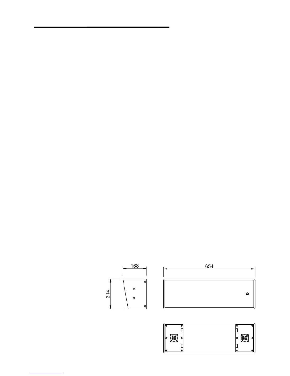
The C6 loudspeaker has been specifically designed for home
theater use. The stylized design, the high quality non-glossy
lacquer finishing, the high SPL and a superb sound quality
allow it to be used on all the functions: Left, Center, Right,
Surround and Ceiling.
The baffle is tilt 10º and permit a flat mounting on the wall or
ceiling while focusing the sound to the listening area. It can
be placed horizontal, vertical or on the ceiling with the same
bracket. For a better integration in the room decoration, the
loudspeaker distance to the wall is only 1 cm and the bracket
is almost invisible. It can be used as well with a pole.
The C6 cabinet is made of 9mm MDF with double thickness
baffle and use an accurate designed bass reflex system for
an extended bass frequency response with a coaxial 6.5”
woofer and 1” compression driver for clear and powerful
sound reproduction free of phase problems.
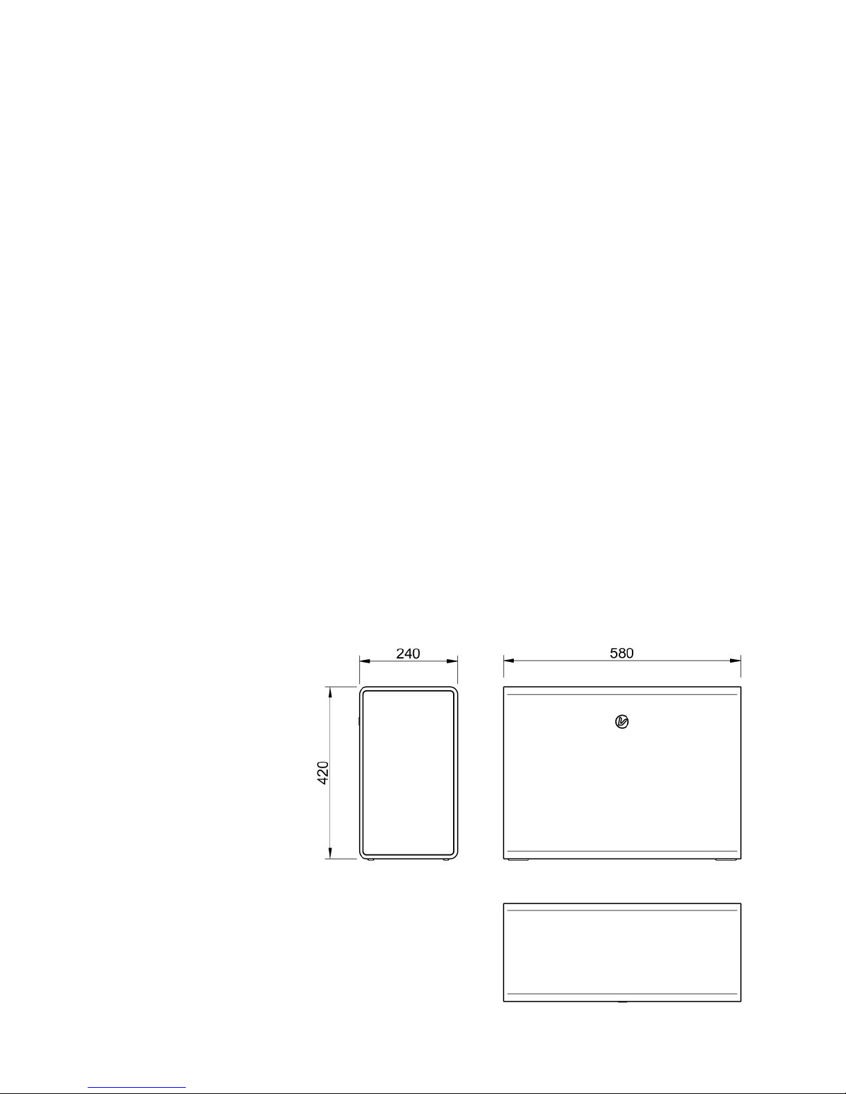
The SUB208S and SUB408S are composed of two and four 8”
drivers respectively and use an innovative symmetrical
configuration of the drivers and ports that allow a flat design
and a practically vibration free cabinet. The main benefits of
the symmetrical flat design are to avoid the comb filtering
produced by the rear wall sound reflections, and the absence
of vibration of the cabinet panels due to action-reaction
movements, allowing the SUB208S and SUB408S deliver the
most clear, balanced and undistorted sound. The flat design
(only 240mm deep) allow the SUB208S to be mounted on a
wall. The vibration free cabinet avoid the problems of sound
transmission to other rooms by the building structure.
The heavy braced cabinets are made of 15 and 18mm MDF
respectively, with double thickness baffle to improve its
sound performance by making its structure very rigid and
avoiding undesired cabinet vibrations.

2. SPECIFICATIONS
2.1. C6
Acoustics
Power: 150W AES, 300W Program, 600W Peak
Impedance: 8Ω
Sensitivity: 92dB SPL 1W/1m half space (1)
Max. SPL @1m: 114dB Continuous, 117dB Program, 120dB Peak
Frequency response: 65Hz-15kHz (-6dB), 60Hz-18kHz (-10dB) (2)
Beam aperture -3dB: 100º ±30º 600Hz-3.5kHz, 60º ±30º 3.5kHz-14kHz
Beam aperture -6dB: 120º ±30º 600Hz-3.5kHz, 90º ±30º 3.5kHz-20kHz
Maximum listener distance: 8m (3)
Recommended amplifier: 300W / 8 Ω
Recommended Xover freq.: 70Hz
Speaker components
1 x Coaxial 6.5” woofer 1” comp. driver
Mounting
Wall / Ceiling: 4 x M6 Screws
on left and right faces for vertical or
horizontal mounting by hidden bracket
Pole: 4 M6 insertion points on
left and right faces for pole adaptor
Size / Package Size:
W654xH214xD168 /
W750xH311xD277
Cabinet
CNC made 9mm MDF,
smooth non-glossy white or
black painting
Connectors
2 x Push terminals for input
and stack output
Net Weight / Gross Weight
9kg / 14kg
1- Measured half space at 2m scaled to 1m full space
2- Measured half space at 4m, curve smoothed 1/3 oct
3- In accordance with dolby® SPL requirements

2.2. SUB208S
Acoustics
Power: 700W AES, 1400W Program, 2800W Peak
Impedance: 8Ω
Sensitivity: 92dB 1W/1m half space (1)
Max. SPL @1m: 120.5dB Cont., 123.5dB Program, 126.5dB Peak
Frequency response: 48Hz-1.1kHz (-6dB), 40Hz-1.5kHz (-10dB) (2)
Directivity: Omnidirectional in the usable range
Recommended amplifier: 1400W / 8 Ω
Recommended HP filter: 35Hz - 12dB/oct - Butterworth
Speaker components
2 x 8" European Ferrite driver
Mounting
On floor
On Wall: 8 M8 insertion points on rear
face for wall bracket
Size / Package Size:
W580xH420xD240 /
W673xH517xD337
Cabinet
CNC made 15mm MDF,
smooth non-glossy white or
black painting
Connectors
1x Euroblock 42A rated with
locking screws
Net Weight / Gross Weight
21kg / 26kg
1- Measured half space at 4m scaled to 1m
2- Measured half space at 4m, curve smoothed 1/3 oct

2.3. SUB408S
Acoustics
Power: 1400W AES, 2800W Program, 5600W Peak
Impedance: 4Ω
Sensitivity: 94.5dB 1W/1m half space (1)
Max. SPL @1m: 126dB Continuous, 129dB Program, 132dB Peak
Frequency response: 33Hz-250Hz (-6dB), 30Hz-350Hz (-10dB) (2)
Directivity: Omnidirectional in the usable range
Recommended amplifier: 2800W / 4 Ω
Recommended HP filter: 30Hz - 12dB/oct - Butterworth
Speaker components
4 x 8" European Ferrite driver
Mounting
On floor
On Wall: 4 hanging slots on rear face
for wall bracket
Size / Package Size:
W940xH560xD240 /
W1092xH657xD337
Cabinet
CNC made 18mm MDF,
smooth non-glossy white or
black painting
Connectors
2x Euroblock 42A rated with
locking screws
Net Weight / Gross Weight
44kg/53kg
1- Measured half space at 4m
scaled to 1m
2- Measured half space at 4m
curve smoothed 1/3 oct

2.4. CURVES
C6 SPL @4m scaled to 1W/1m half space C6 Impedance
SUB208S SPL @4m scaled to 1W/1m half space SUB208S Impedance @1V
SUB408S SPL @4m scaled to 1W/1m half space SUB408S Impedance @1V
10k5k2k1k50020010050.020.020.0 20kHz
110
dBSPL
100
90.0
80.0
70.0
60.0
Verity AudioLogChirp - Frequency Response26-09-2018 12.09.02
10k5k2k1k50020010050.020.020.0 20kHz
100
Ohm
80.0
60.0
40.0
20.0
0
Verity Audio Sinusoidal 26-09-2018 11.55.12
2k1k50020010050.020.020.0 2kHz
110
dBSPL
100
90.0
80.0
70.0
60.0
Verity AudioLogChirp - Frequency Response21-12-2017 14.25.26
2k1k50020010050.020.020.0 2kHz
100
Ohm
80.0
60.0
40.0
20.0
0
Verity Audio Sinusoidal 21-12-2017 16.42.06
2k1k50020010050.020.020.0 2kHz
110
dBSPL
100
90.0
80.0
70.0
60.0
Verity AudioLogChirp - Frequency Response12-06-2017 16.06.21
2k1k50020010050.020.020.0 2kHz
50.0
Ohm
40.0
30.0
20.0
10.0
0
Verity Audio Sinusoidal 26-09-2018 15.25.30

3. CONFIGURATIONS
3.1. A bit of history
The sound cinema started on late 30s with only one
loudspeaker on the center of the screen. Different recording
systems were used and the optical track on a 35mm film was
finally standardized.
During the 50s and 60s special expensive 70mm films with 6
magnetic tracks were recorded. The screen was filled with 5
channels (left, center left, center, center right and right) and
the 6th channel was for surrounding effects.
Later, in the 70s, dolby introduced a second optical track on
the 35mm films: the dolby stereo. A matrix technology
permitted to get 4 channels from the 2 optical tracks. Left,
center, right and surround.
With the introduction of digital technology early 90s,
different systems reach to record 6 sound channels. A sub
bass LFE (low frequency effects) was added: the .1 of the
5.1 loudspeakers configuration.
At present, the digital technology for video and audio
recording has no limitation of the number of sound channels.
The latest one, dolby atmos, allow until 128 sound tracks
that are mixed, processed and directed to the loudspeakers
depending on the number and position of them.
3.2. Configurations numbering
The first number of the different configurations mean the
number of front and surrounding loudspeakers.
The second is the number of LFE loudspeakers (also called
subwoofer despite his main function in home cinema is not
the same as the subwoofer in hi-fi systems).
And the third is the number of overhead loudspeakers.
So, a 7.2.4 configuration mean: screen Left, Center and
Right, surround Left, Right, Rear left and Rear right, 2 LFE
and 4 overhead loudspeakers.

3.3. Loudspeakers acronym
There is a standard acronym to identify easily the different
loudspeakers. This is a list of the main ones:
C Screen center
L Screen left
R Screen right
Ls Left surround
Rs Right surround
Lrs Left rear surround
Rrs Right rear surround
Ltf Left top (overhead) front
Rtf Right top (overhead) front
Ltr Left top (overhead) rear
Rtr Right top (overhead) rear
3.4. Loudspeakers placement
The placement details in this section are accordingly with
the dolby atmos recommendations based in the standards
ITU-R BS.775-3 and ITU-R BS.1116-1
fig 1 - Vertical layout

The best position for the front and surrounding loudspeakers
is at the ears level of the audience. This mean the C6
cabinet center must be at around 1.2m from the floor. The
rear surround loudspeakers could be placed 1.25 times
higher than the front ones, so is at 1.5m.
The overhead loudspeakers must be at a height of 2 to 3
times the height of the front ones, so is between 2.4 and
3.6m, that is usually the height of the ceiling in homes.
fig 2 –Horizontal layout
The SUB208S or SUB408S placement could be at any place
on the front of the audience and against a wall for a smooth
and linear bass reproduction. Generally, it is better not to
place it on symmetry axes of the room, like the center of the
front wall. If two or more SUB are used, not place them
symmetrically to the room, so is, on the front wall at the

same distance of the left and right walls. This is to minimize
the effects of the room reflections.
Loudspeakers but C and LFE should be added to the system
by pairs and placed as symmetrically as possible to the axe
from the listening position to the screen. It is important to
understand that to get the best sound experience, the sound
should come from symmetrically placed loudspeakers. No
matter if there are distance differences, because the sound
level can be compensated by the processor, but the angle
should be the same for the left and right loudspeakers.
3.5. Typical configurations
Below are the placement drawings for some standard setups.
For non-overhead loudspeaker configurations simply not
consider them.
Fig 3 - x.x.2 Overhead position Fig 4 - x.x.4 Overhead position
Fig 5 - 5.1.2 Layout Fig 6 - 5.1.4 Layout

Fig 7 - 7.1.2 Layout Fig 8 - 7.1.4 Layout
Fig 9 - 9.1.2 Layout Fig 10 - 9.1.4 Layout
3.6. Speaker level calibration
Each full range speaker should be calibrated to get the same
SPL at the central listening position. The target SPL can
range from 79 to 82dB when driving with pink noise with an
RMS level of -20dB relative to full scale.
Set the crossover frequency to 70Hz and calibrate the
subwoofer level at the central listening position for
redirected bass content from the full range loudspeakers to
the same level of those calibrated before.
If you use the autocalibration setup included in your AVR or
processor, please double check manually the levels on the
subwoofer and overhead loudspeakers.

4. C6 INSTALLATION
4.1. Placement
The C6 home cinema speaker can be placed on pole, on
shelf, on wall or on the ceiling. On wall the position could be
horizontal or vertical, depending on the room and installation
conditions.
The C6 aperture angle of the sound beam is great and the
cabinet not need to be precisely focused to the listening
point. It can be installed with the tilt baffle facing the
listening point and keep flat against the wall.
4.2. Wall/ceiling installation
Use the appropriate screws or
anchors to fix the supplied wall
bracket to the wall or ceiling.
Place it horizontally or
vertically as you need.
Place the C6 on the bracket
and fix it with only 2 M6 screws
to allow to rotate the cabinet
for an easy cable connection.
Use 2 more M6 screws to finish
the installation. Double check
the screws are enough tighten.
When using the wall
bracket it is recommended
to use safety cables
attaching them in the
holes of the cabinet and
bracket for this purpose.
4.3. Pole installation
A pole adaptor can be fixed on the left or right side of the
C6. Only vertical loudspeaker position is possible with a
pole. Remove and use the 2 M6 screws that are in the faces
to do it.
Fig 11 –Wall bracket install
Fig 12 –Safety cables place

5. SUB208S / SUB408S INSTALLATION
5.1. Placement
The SUB208S and
SUB408S can be
placed on the floor
or hung on a wall. In
any case there must
be at least 25cm of
free space in front of
both radiating faces.
When used on the
floor, place the
subwoofer as close
as possible to a
wall.
5.2. SUB208S Wall mount
The SUB208S wall bracket is composed
of two identical pieces. Use the
appropriate screws or anchors to fix
them to the wall. Take care to place the
two brackets with the flange facing up,
perfectly leveled and at the distance of
380mm between the center points. You
can use the included template to
facilitate the installation.
The SUB208S can be hung
face up or face down to
facilitate the wiring depending
if the cables come from the
floor or from the ceiling. For a
face up installation use the 4
insert points with M6 screws on
top of the rear face to attach
the 2 small omega shaped
plates of the bracket. For a
face down installation use the
4 on the bottom.
Fig 13 –Subwoofer minimum wall distance
Fig 14 –SUB208S brackets
Fig 15 –Face up omega plates

5.3. SUB408 Wall mount
The SUB408S wall bracket is
composed of two identical
pieces. Use the appropriate
screws or anchors to fix them
to the wall. Take care to place
the two brackets with the
flanges facing up, perfectly
leveled and at the distance of
700mm between the center
points. You can use the
included template to facilitate
the installation.
The SUB208S can be hung
face up or face down to
facilitate the wiring depending
if the cables come from the
floor or from the ceiling.
6. WIRING
The C6 have two sets of push terminals to connect the
cables, one on each side of the rear face. Can use any of
them or the signal input. The other can be used to parallel
connect a second C6 to the same channel. Use the red one
for + connection and the black one for –connection.
The SUB208S and SUB408S use a high current Euroblock
connector for the signal input. Two locking screws avoid it
be accidentally unplugged.
Use a cable with the
appropriate gauge to connect
the subs to the amplifier. As a
rule, use 2x2.5mm2cable for
lengths up to 10m and 2x4mm2
cable for longer lengths.
You can use the stack output
connectors for a parallel
connection of another
subwoofer.
OUT –
AMPLIFIER
OUT +
Fig 16 –SUB408S brackets
Fig 17 –Euroblock connector
+
-

Verity audio reserves the right to make any changes to the product specifications without prior notice.
Final specifications to be found in the user manual
© VERITY AUDIO - France * all rights reserved
This manual suits for next models
2
Other Verity Audio Home Theater System manuals