Verizon Visirun B1N User manual

VISIRUN
Installation
Manual

Installation Manual v1.16
V I S I R U N
InstallationManualv1.16

Installation Manual v1.16
TableofContents
Table of Contents................................................................................................................................. 2
Security warnings................................................................................................................................. 3
Package contents................................................................................................................................. 4
Important notes for the installer......................................................................................................... 5
GPS tracker configuration.................................................................................................................... 5
GPS tracker positioning........................................................................................................................ 5
GPS tracker installation........................................................................................................................ 6
GPS/GSM combined Antenna connection and positioning................................................................. 7
GPS tracker fastening........................................................................................................................... 7
Installation check ................................................................................................................................. 8
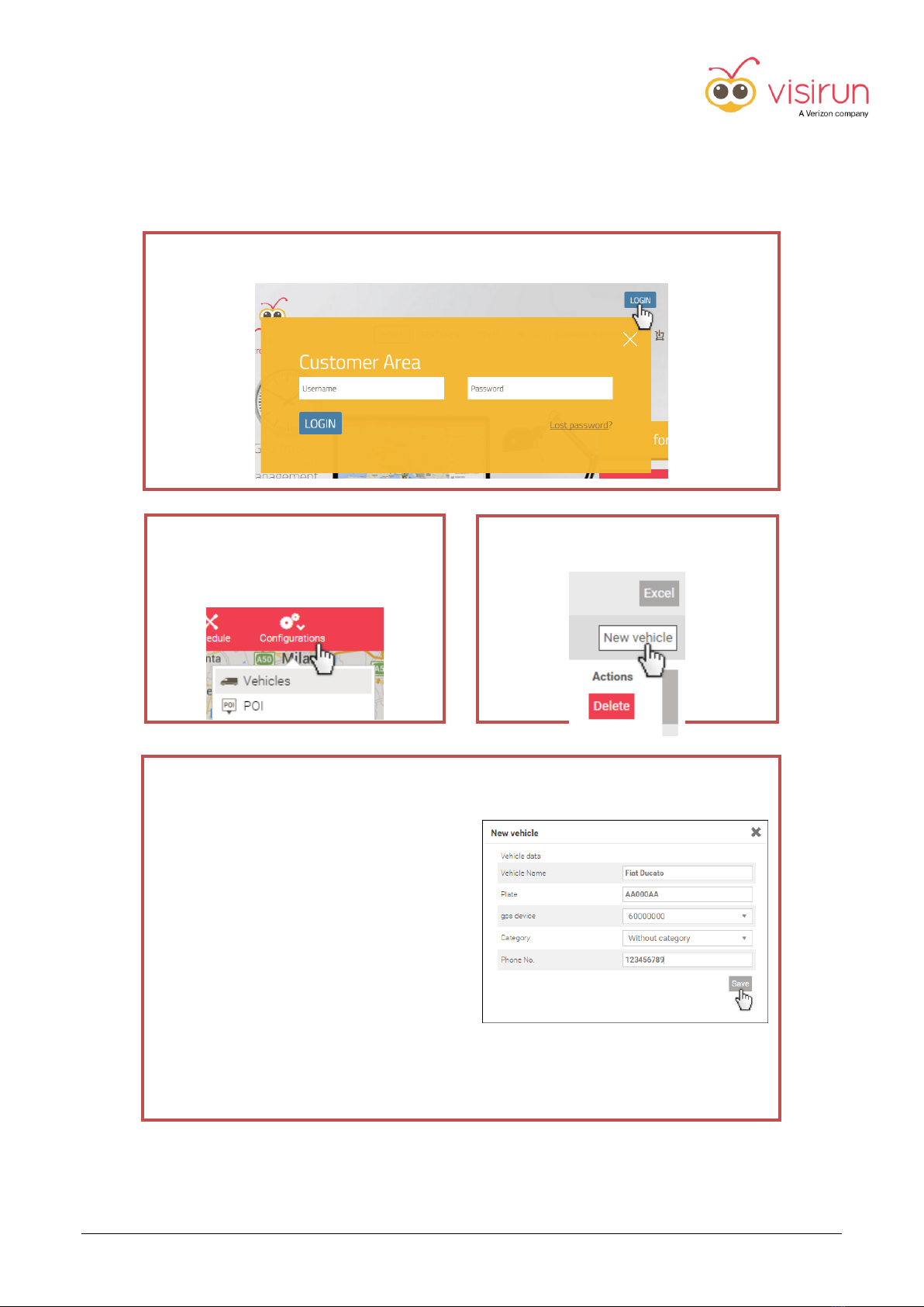
GPS tracker activation.......................................................................................................................... 9
Optional connections......................................................................................................................... 11
General connection schemes............................................................................................................. 13
Real-time data from digital tachograph via K-Line............................................................................ 14
Tachograph Remote Download Kit.................................................................................................... 15
IP67 Outdoor Kit ................................................................................................................................ 16
IP67 Outdoor kit for Containers......................................................................................................... 17
Mobile Document Scanner ................................................................................................................ 18
Mobile Document Scanner installation ............................................................................................. 19
How to use the Mobile Document Scanner....................................................................................... 19
GNU Licenses for B2/B1N/R1N-T tracker .......................................................................................... 20

Installation Manual v1.16
3
Securitywarnings
Consider these security warnings when you install, use and maintain the B1N / B2 / R1N-T products.
A. Electronic medical devices
In hospitals or in other medical infrastructures, follow the local instructions regarding cellular mobile
devices.
Radiofrequency waves emitted by the product could interfere with electronic medical devices,
pacemakers o other devices used by patients. Refer to the medical device vendor to verify security
warnings before using the product nearby patients.
B. Airfreight
In case of airfreight, remember to switch off the product.
It’s forbidden to operate with cellular mobile devices during the flight.
C. Inflammable substances
Do not use the product nearby inflammable substances.
Switch off the product when it is entering in explosion risk area (e.g.: fuel or other chemical substances
storage area).
Using an electronic device in potentially explosive atmosphere is a severe security risk.
D. Radiofrequency interferences
This product emits radiofrequency waves in the GSM frequency band and it could interfere with other
radiofrequency devices.
Do not use the product nearby other radiofrequency devices if interferences can damage those devices.
E. Emergency calls
The product cannot be used for emergency calls.

Installation Manual v1.16
4
Packagecontents
The Visirun GPS tracker kit is composed by:
1. Visirun GPS tracker (B1N / B2 or R1N-T model, see page 17)
2. GPS/GSM combined Antenna with black cable (3m length)
3. Power cable (2m length) with 16-pin MOLEX connector ready for connection to a permanent
power source of 12/24V, ignition connection, digital inputs, digital outputs and analog inputs,
primary CAN-BUS interface for B2 model.
4. (B2 model only) 20-pin MOLEX connector for extra connections (additional digital input/output,
secondary CAN-BUS interface, K-Line and J1708 interfaces).

Installation Manual v1.16
5
Importantnotesfortheinstaller
IMPORTANT NOTE
The product installation must be performed by a qualified technician who must follow the instructions
reported in the manual.
GPS tracker configuration
The Visirun GPS tracker is fully configured and ready to use.
It is identified by a SERIAL NUMBER reported on a label on the top side.
To start using the GPS tracker simply plug it to a power source and connect the GPS/GSM Antenna as
described in this manual.
GPS tracker positioning
Place the tracker anywhere INSIDE THE DRIVER'S CAB, hidden if you wish (e.g.: under the dashboard,
behind the radio, inside the fuse compartment). See the instructions on page 6 for GPS/GSM combined
Antenna connection and positioning.
Crash detection function
The crash detection function is not enabled by default, the customer must request to enable this
function during the installation.
This function can work properly only if the device is fastened to the cab structure.
The GPS tracker is NOT guaranteed to work properly if installed outside the driver’s cab, such as
in the engine compartment. It requires an operational temperature in the range -20°/+60° C.
B1N and B2 products are IP40 certified therefore they cannot be used outdoor and cannot be
exposed to outside elements.
An improper use can damage the GPS tracker or the vehicle.
For outdoor use, the IP67 Outdoor kit is available (see page 17).

Installation Manual v1.16
6
GPStrackerinstallation
1. Plug the 16-pin MOLEX into the CN1 socket on the back of the GPS tracker (in B2 model CN1
socket is the farthest socket from the BLUE and PURPLE FAKRA sockets)
2. Connect the RED and BLACK wires to the vehicle's power supply of 12 or 24V DC. The GPS tracker
power cable already includes a FUSE.
NOTE
The GPS tracker must be permanently powered on.
The current consumption is very low and the device must remain powered on even if the vehicle's
engine is turned off.
The GPS tracker has an internal battery that would damage in a few months if not connected to a
permanent power source (e.g.: cigarette lighter).
NOTICE
In standard conditions, the GREEN wire is connected to the RED power wire into the
fuse holder. To increase tracking precision, it’s necessary connecting the GPS tracker to
the vehicle's ignition connection using the GREEN wire available in the 16-pin MOLEX
connector.
3. Cut the GREEN wire shortly before the fuse holder and connect it to a power source available
only when the ignition is on and absent when the ignition is off. Protect this connection with a 2A
fuse (not provided with the Visirun GPS tracker kit).
NOTE
This option requires a specific device configuration so, please contact the Technical Support requesting
the proper device configuration update (GPS tracker serial number is needed).

Installation Manual v1.16
7
GPS/GSMcombinedAntennaconnectionandpositioning
The supplied GPS/GSM Antenna consists of:
•GPS / GSM signal reception rounded element
•3m dual wire connection cable
•2 FAKRA connectors:
oBLUE FAKRA for GPS signal
oPURPLE FAKRA for GSM signal
To connect the GPS/GSM Antenna to the Visirun tracker:
1. Plug the BLUE FAKRA (GPS) into the BLUE socket on the back of the tracker.
2. Plug the PURPLE FAKRA (GSM) into the PURPLE socket on the back of the tracker.
NOTE
For better signal reception, place the rounded element next to the windshield, for example onto the
vehicle's dashboard. You can hide the Antenna (e.g.: inside the dashboard) but be sure the rounded
element is not surrounded by metal surfaces or near other electronic devices (e.g.: Bluetooth devices
or GPS Navigator).
The adhesive label (GPS side) must be facing up or out with a clear view of the sky.
GPS tracker fastening
To increase tracking precision, fasten the GPS tracker to the cab structure.

Installation Manual v1.16
8
Installationcheck
You can use the diagnostic LEDs to verify if the device is properly installed and working.
•LEFT LED (GPS): RED if the GPS satellites signal is properly acquired
•CENTRAL LED (BATTERY): ORANGE while charging the internal battery, GREEN when battery is
fully charged
•RIGHT LED (GSM): YELLOW flashes twice if it is properly communicating
FOR AN ACCURATE VERIFICATION USE OUR AUTOMATIC SMS INSTALLATION CHECK (see page 21)
NOTE
Follow instructions on the next page to activate Visirun tracker and see your vehicle on
www.visirun.com.

Installation Manual v1.16
9
GPStrackeractivation
The GPS tracker is already fully configured and ready to use.
Go to www.visirun.com to pair the Visirun GPS tracker with the vehicle on which it is installed.
4. Fill in all the fields in the [New vehicle]
form
•Vehicle name
•Vehicle's license plate
•Click the drop down [gps device] list
and select the SERIAL NUMBER of
the Visirun GPS tracker you have
just installed
•Category
•Driver's phone number
5. Click on [Save]
To confirm your choices.
Go to n. 8
1. Click on [LOGIN] and enter your E-MAIL and PASSWORD.
2. Click on [Configurations] in the top
menu bar and then on [Vehicles] in
the dropdown menu
3. Click on [New vehicle] on the right
of the list

Installation Manual v1.16
10
8. Move your vehicle
To see the vehicle on the Map
section
If you want to pair the just installed tracker with an existing vehicle
6. Click on the vehicle's name
7. Click on [Pencil] on the right of the
[gps device] field and select the SERIAL
NUMBER of the Visirun GPS tracker
you have just installed

Installation Manual v1.16
11
Optionalconnections
The Visirun GPS tracker allows the following optional connections:
DESCRIPTION
CASES OF USE
CONNECTION
K-Line Interface (B2 model only)
Driver Recognition,
Reading real-time data from
digital tachograph
RECOMMENDED OPTION
CN2, pin 20 and 15.
See circuit diagram on page 15
Primary CAN-BUS interface (B2 model
only)
Reading real-time data from CAN-
BUS network and digital
tachograph, etc.
CN1, pin 14 and 15.
SAE J1708 interface (B2 model only)
Reading real-time data from SAE
J1708/J1587 network
CN2 pin 12 and 13
Secondary CAN-BUS interface (B2 model
only)
Remote data download from
digital tachograph.
CN2 pin 10 and 9.
See circuit diagram on page 16
Remote device activation/deactivation
control (12 / 24V active, 0V deactivated)
Door opening control, anti-
robbery button, digital input, etc.
CN1, pin 5, 7 e 10, connector CN2 pin 1
(CN2 only on model B2).
Temperature Control with Visirun
temperature probe
CN1, pin 4 connected to the light blue
wire of the Visirun temperature probe
Fuel level real time control
CN1, pin 8 connected to the vehicle’s
factory-fitted float control output 0-12V
Remote engine cut-off
CN1, pin 13 as mass control for the cut-
off relay (maximum consumption 300
mA)
IP67 Outdoor kit
Additional protection for outdoor
use. For trailers, swap bodies, etc.
See page 17
Privacy function activation/deactivation
control (12 / 24V active, 0V deactivated)
When this function is active, the
device stops to acquire data and it
doesn’t trace the route of the
vehicle.
CN1, pin 5, 7 e 10, connector CN2 pin 1
(CN2 only on model B2). Connect an
ON/OFF switch to 12/24V power source

Installation Manual v1.16
12
Additional accessories are available and can be easily connected through the quick lock circular
connector or MOLEX connector:
Security Kit with Numeric Keypad
Operators' recognition and attendance
management Kit
On board Terminal/ GPS Navigator
Tachograph Remote Download Kit
(B2 model only)
Mobile Document Scanner
(B2 model only)
The keypad and Operator’s recognition and attendance
management kit include the relay to inhibit the engine start
assembled in the molex connector with accessory plug.
The relay uses the BROWN and BLU wires to forbid the engine
start and the ORANGE wire is not use.

Installation Manual v1.16
13
Generalconnectionschemes
For detailed information about accessories installation, refer to the provided additional documentation.

Installation Manual v1.16
14
Real-timedatafromdigitaltachographviaK-Line
Direct connection via K-Line allows Visirun GPS tracker to read real-time data from digital tachographs,
including driver recognition and state.
The direct connection is available only for the B2 model:
1. Connect pin 15 of the CN2 connector (BLUE / BLACK wire) to pin 8 of the D connector on
the back of the tachograph.
2. Connect pin 20 of the CN2 connector (BLACK wire) to pin 6 of the Cconnector on the back
of the tachograph.

Installation Manual v1.16
15
TachographRemoteDownloadKit
The Tachograph Remote Download Kit allows the Visirun GPS tracker to remotely download data from
digital tachographs, both Vehicle Unit and Driver Card, without the need to go on board of each
vehicles.
This kit is available only for the B2 model.
Connect the Remote Download cable according to the following scheme: plug the red AMP connector
into the C connector on the back of the Tachograph and connect the two wires to pin 9 and 10 of the
GPS tracker:
NOTE
In addition to the Tachograph Remote Download Kit, we recommend the direct connection via K-Line to
read real-time data from digital tachographs shown on the previous page.

Installation Manual v1.16
16
IP67OutdoorKit
The IP67 Outdoor Kit is designed to install the GPS tracker onto trailers, containers, swap bodies, and
construction site equipment with no cab or no permanent power supply. The kit includes an IP67
waterproof enclosure for outdoor use and a long-life battery guaranteed to run 45 days.
The device is configured to minimize power consumption when external power is not present (e.g.:
trailer detached from tractor). It has a multi-connector cable with possibility of connection digital input,
analog and digital output for the services of starting block.
NOTE
In order to properly charge the internal battery, the GPS tracker must be connected to 12/24V power
source when the trailer is attached to the tractor.
External antenna installation points:

Installation Manual v1.16
17
IP67OutdoorkitforContainers
IP67 Outdoor kit for Containers is a special version of the IP67 Outdoor kit with additional features:
•Internal GPS/GSM Antenna
•Extended internal battery for tracking without external power
•Powerful internal magnets to temporarily install the tracker on metal (ferromagnetic) surface
IMPORTANT NOTE
IP67 Outdoor kit for Containers embeds powerful internal magnets: do not bring this tracker
closer to devices and systems that can be damaged by magnetic field, e.g.: credit cards and
ATM cards, pacemakers, defibrillators, electric and electronic systems, TVs, laptop
computers, mechanical clocks, loud speaker, etc..
If installed on metal surface with magnets only, there is a risk of tracker detachment during
vehicle's movement.
Detachment risk is related to improper mounting, e.g.:
•mounted on irregular or rough surface
•mounted on a dirty surface (encrusted, rusted or lubricated)
•mounted on a partial ferromagnetic surface, magnets couldn't work properly
•mounted over mobile parts (wires or pipes) that can cause tracker detachment during
movements
Permanent installation with screws is always recommended.

Installation Manual v1.16
18
MobileDocumentScanner
Mobile Document Scanner allows the driver to acquire paper documents that will be available as a
digital copy in the Document section of Visirun.
The kit is available only for the B2 model and it is composed by:
1. Document Scanner
2. USB Scanner cable
3. 5-pin MOLEX to USB cable

Installation Manual v1.16
19
MobileDocumentScannerinstallation
To complete the installation of the Mobile Document Scanner :
•Connect the 5-pin MOLEX to USB cable (3) to the 5-pin MOLEX socket of the GPS tracker.
•Connect the USB Scanner cable (2), plug the mini-USB connector to the scanner (1) and the
other end to the 5-pin MOLEX to USB cable (3).
-The scanner will be charged by the tracker, it is not necessary to connect the scanner power
adapter.
How tousethe MobileDocument Scanner
•Turn on the scanner: press and hold the power button for 3 seconds
•When the blue LED next to the camera icon (scan mode) is powered on, the scanner is
ready for document acquisition. DO NOT CHANGE scan mode because the default one
guarantees the best scan quality.
•Insert a document face up in the paper feed slot, aligned to the left side of the scanner. The
scanner detects the page and starts to feed it through the scanner without any interaction.
NOTE: You do not need to press any button to scan.
•NEVER TURN THE SCANNER OFF MANUALLY, the scanner will be automatically turned off at the
end of the document acquisition process.
NOTE
Do not install the Mobile Document Scanner outside the driver's cab or expose to direct sunlight.
This manual suits for next models
2
Table of contents
Other Verizon GPS manuals