Verizon Asset Guard BX User manual

Verizon Connect
Networkeet
Asset Guard BX
Installation Guide
Table of Contents
Getting Started ...............................................................................................2
Trailer Nose Installation..............................................................................3
Heavy Equipment Chassis Installation ................................................3
Heavy Equipment Magnetic Mount Chassis Installation ............4
Intermodal Container Door Installation...............................................4
Battery Replacement Procedure............................................................5

2
Getting Started
Asset Guard Overview
Asset Guard provides battery powered tracking for your fixed
and movable fleet assets such as trailers, sheds, generators,
heavy duty equipment, and any other property that you may
need to monitor.
The Asset Guard unit includes a replaceable battery, internal
antenna, activation/deactivation magnet and mounting hardware.
Registration & Activation Notes
Fill out the enclosed registration form for your records before
starting physical installation. Be sure to record the Asset Guard
Unit serial number (ESN) along with the label or serial number
used to identify the piece of equipment being managed.
Installation and Verication Notes
• Units need to be activated with Verizon Connect
Networkfleet prior to removing the activation magnet.
• Always remove and retain the activation magnet from the
front of the device enclosure in order to activate device
reporting. Use the activation magnet to disable reporting
upon removal of the device.
• The unit is shipped with a magnet placed on top of the
unit. Upon installation, always remove the magnet from the
front of the device enclosure in order to activate device
reporting. Retain this magnet for future use to disable
reporting upon removal or deactivation of the device.
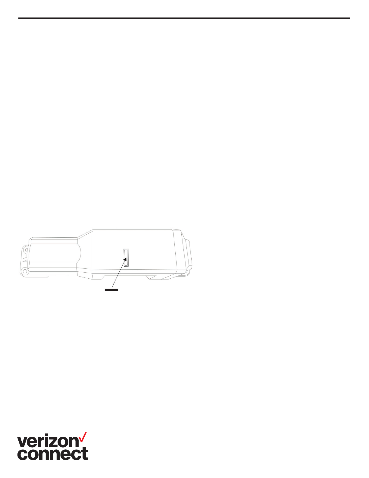
• If you want to disable reporting in the future you will need
to retain this magnet in order to do so. To disable reporting
place the magnet back in the designated groove as seen in
the diagram and secure it with tape.
• Device must be mounted facing up or down for optimum
GPS reception and accuracy.
• Call Verizon Connect Networkfleet Customer Care to verify
successful installation at 1-866-227-7323 opt. 5 (provided
on the device registration card).
• Refer to the following installation examples and select an
installation location where Asset Guard can be mounted
securely and will not be damaged during normal use of the
equipment.

3
Record the Asset Guard serial number (ESN) found on the
device label and the trailer’s identification number.
1. Select a mounting location on the nose rail centered from
side-to-side where device will not be damaged. Place the
mounting flanges against the trailer’s top rail so that round
battery access panel is on the left.
2. Using the device mounting flanges as a template, mark
the location for each of the four (4) mounting screws on
the trailer nose rail.
3. At each marked location, drill a 3/16” hole.
(Safety glasses / eye protection recommended)
4. Remove any metal shavings from hole and cross member
surfaces.
5. Install the mounting screws (4) through the mounting
flanges and into the trailer’s top rail.
6. Tighten screws (4).
Record the Asset Guard serial number (ESN) found on the
device label and the trailer’s identification number.
CAUTION: Remember to mount Asset Guard in a location it will
not be damaged by stacking or by normal operation.
1. Using the device mounting flanges as a template, mark the
location for each of the four (4) mounting screws on the
trailer cross member.
2. At each marked location, drill a 3/16” hole.
(Safety glasses / eye protection recommended)
3. Remove metal shavings from holes cross member
surfaces.
4. Mount device using screws (4), flat washers (4) and self-
locking nuts (4). Ensure flat washer is between screw
head and plastic device housing.
5. Tighten each screw using 5/16” socket, ratchet and 3/8”
open-end wrench.
Trailer Nose Installation
Heavy Equipment Chassis Installation

4
Record the Asset Guard serial number (ESN) found on the device label and the
trailer’s identification number.
CAUTION: Remember to mount Asset Guard in a location it will not be damaged
by stacking or by normal operation. Choose a location that is rust free and level
on a cross member that the lanyard can wrap around or a hole can be drilled to
extend it through.
1. Clean mounting surface where magnets will contact frame member.
• For dirt and grease use acetone
• For rust or loose paint use a wire brush and acetone
2. Mount device and ensure all four (4) magnets are engaged.
3. If required, drill 1/4” hole in frame member, remove any shavings and pass
lanyard through; otherwise, loop lanyard around the frame member.
(Safety glasses / eye protection recommended)
4. Feed threaded link through lanyard loops and lanyard clip.
5. Apply blue Loctite to threaded link threads.
6. Tighten threaded link with two Crescent wrenches.
Record the Asset Guard serial number (ESN) found on the device label and the
trailer’s identification number.
CAUTION: Remember to mount Asset Guard in a location it will not be damaged
by stacking or by normal operation.
1. Mount Asset Guard on top left or right door between the locking rods at
the base of the corrugated well in a rust free and level position.
2. Level device in mounting area with label facing down.
3. Mark all four (4) mounting holes.
4. At each marked location, drill a 3/16” hole.
(Safety glasses / eye protection recommended)
5. Apply RTV sealant inside the mounting holes.
6. Feed mounting screws from inside container door.
7. Mount device on screws and tighten nuts.
8. If using magnetic mount option follow magnetic mount instructions and
loop lanyard around locking bar.
Heavy Equipment Magnetic Mount Chassis Installation
Heavy Equipment Chassis Installation

Before starting this procedure, uninstall the device
and place it on a flat surface
1. Remove Battery Cap
• Insert Phillips head screw driver and remove
the four screws. Remove the end cap and
set aside. The two screws securing the
device also need to be removed.
2. Disconnect Power Cable-First, Remove the
rubber gasket and set aside.
• Disconnect the red and black power cable
by pulling two connector halves apart.
• Do not pull on the power wires.
3.Remove Battery Pack
• Ensure gap in battery pack foam is aligned with
device power cable. Slide the battery pack out
of the enclosure being careful not do damage or
drop the circuit board
4. Replace Battery Pack
• Holding the circuit board inside the unit, slide
replacement battery pack into the enclosure
5. Reconnect Power Cables
• Replace gasket and reconnect the white connectors.
6. Replace Battery Cap
• Seat the cap housing to the gasket to ensure a tight
fit. Insert the screws using a Phillips head screwdriver
and turn clockwise until hand tight.
For questions or more information, contact your Customer Success Manager or
email sdcustomersuccess@verizonconnect.com
Battery Replacement Procedure
©2018 Verizon. All rights reserved.
Table of contents
Other Verizon GPS manuals