Verizon RFS HYBRIFLEX HBF058-08U1S1 Series User manual

RFS INSTALLATION INSTRUCTIONS
VERIZON HYBRIFLEX CABLE| Revision 1 | APRIL 2019
Visit www.rfsworld.com for the most current product specifications
Page 2 of 33
Table of Contents
RFS HYBRIFLEX Introduction
3
Hybrid Jumper Installation
4
Riser Trunk Diagrams/Configurations (Examples)
7
Transporting, Shipping, and Handling the Drum
9
Protective Sleeve Removal/Packing
10
Hoisting/Pulling HYBRIFLEX Cable
11
HYBRIFLEX Bending
12
Fixation/Mounting of the Cable
14
Installation of the Grounding Kit
16
Armor Cutting Tool Instructions
19
Armor Removal Ripcord Instructions
21
Fiber Inspection, Cleaning
25
Installation of HYBRIFLEX Into the OVP's
31

RFS INSTALLATION INSTRUCTIONS
VERIZON HYBRIFLEX CABLE| Revision 1 | APRIL 2019
Visit www.rfsworld.com for the most current product specifications
Page 3 of 33
Introduction to HYBRIFLEX
RFS’ HYBRIFLEX Remote Radio Head (RRH) hybrid feeder cabling solution combines optical fiber and DC
power for RRHs in a single lightweight cable, making it the world’s most innovative solution for RRH
deployments. It was developed to reduce installation complexity and costs at macro sites. HYBRIFLEX allows
mobile operators deploying RRH architecture to standardize the RRH installation process. HYBRIFLEX
combines optical fiber, power, and alarm wire in a single jacketed cable and can connect multiple RRHs with a
single feeder. Standard RFS CELLFLEX®accessories can be used with HYBRIFLEX cable. Both pre-terminated
and on-site terminated options are available.
The rugged jacket facilitates easy transportation, handling, and installation.
These short instructions were written for qualified and experienced personnel. They describe, in few words,
the main points that MUST be noted during installation, without any claim of completeness.
Any liability or warranty for results of improper or unsafe use is disclaimed!
General remarks:
In principle, care must be taken to avoid all such strain that may cause permanent deformation on the cable,
e.g. going below admissible bending radii, kinking, applying too high tensile stress or forcible deformation (e.g.
pulling over sharp edges, over tightening of clamps etc.).
Click or scan to learn more
about RFS HYBRIFLEX®

RFS INSTALLATION INSTRUCTIONS
VERIZON HYBRIFLEX CABLE| Revision 1 | APRIL 2019
Visit www.rfsworld.com for the most current product specifications
Page 4 of 33
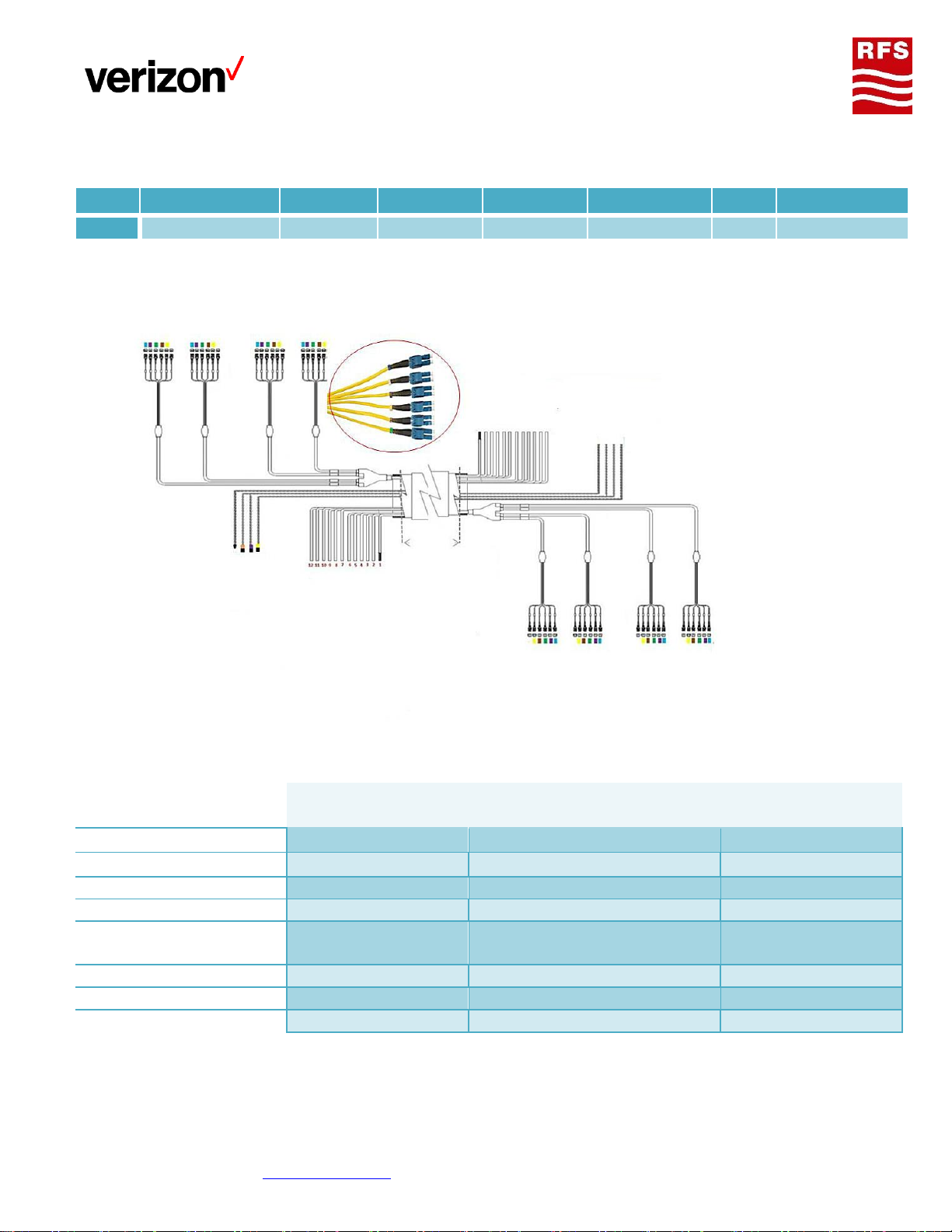
Verizon HYBRIFLEX® cable is unique to its network available
in three Trunk configurations, 2x4 (mainly for rooftop) 6x12
and 12x24. The trunk cable assemblies comprise of 6 AWG
Low Inductance DC wires, nine 18-gauge alarm wires and up
to twenty four (24) pairs of single Mode fiber terminated
with LC-LC connector.
The use of Low Inductance Cable will allow Maintenance
Engineering to extend distances upwards of ~600ft,
eliminating the need to re-locate power cabinets and stay
within the conventional distances supported. Refer, to
previous installation instruction for older traditional Hybrid.
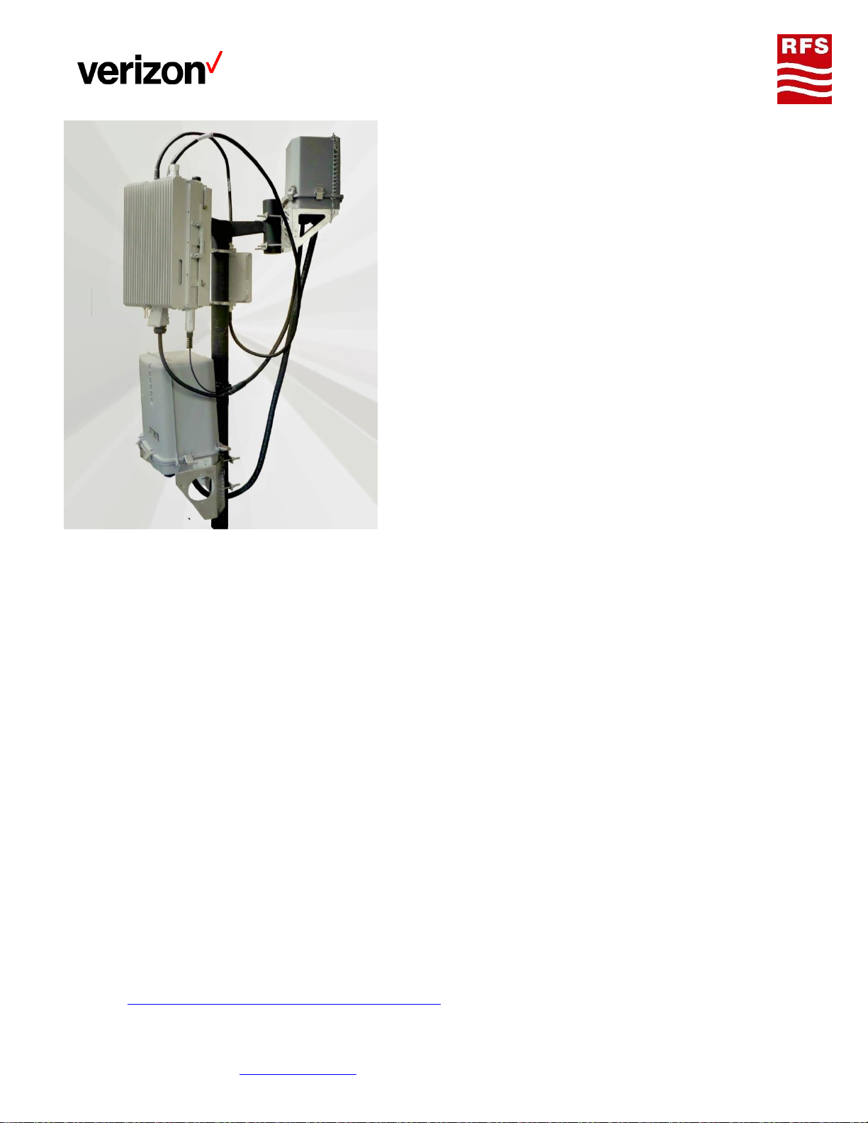
Verizon uses a combination of OVP’s (over voltage
protection) both top and bottom and various hybrid jumpers
configuration for complete installation from BBU to RRH.
HYBRIFLEX® trunk cable assemblies are factory constructed
specifically to suit the Verizon Network, ensuring perfect
Raycap OVP’s compatibility and trouble-free installation.
Additional features that ease installation and ensure
durability service include:
Robust breakout design with Numbering fibers and
power conductors
Stranded construction for easy bending and maximum fiber protection
Corrugated aluminum shield protects from crush and animal damage
Integrated rip cords for length management
Factory test certificate available for every cable assembly
Well packaging, easy fiber End face access for pre-testing
Caution: not to be stored outside
Hybrid jumpers Installation
In general Hybrid jumpers are installed similarly to trunk line or coaxial cable. Used accessories where
applicable.
The Fiber endface must be handling with care and be protected during installation.
DO NOT remove protected tubing and plastic bag until ready to connect the jumper between OVP box
and RRU or BBU.
Followed the bend radius guidelines specify in the product spec sheet
Attach the main cable securely to the structure or equipment using hangers and/or cable ties to
prevent strain on connections from movement in wind or snow / ice conditions.
Ensure all LC optical fiber connectors are seated firmly in the OVP box, RRU or in BBU equipment.
Ensure the weatherproof boots for both fiber and power connections and seated firmly in the RRU
All Hybrid jumpers and risers are individually serialized, for immediate access to test results visit
http://myrfs.rfsworld.com/hybriflex/Default.aspx, Power connector is supplied with the RRU

RFS INSTALLATION INSTRUCTIONS
VERIZON HYBRIFLEX CABLE| Revision 1 | APRIL 2019
Visit www.rfsworld.com for the most current product specifications
Page 5 of 33
Red power conductor is -48V
Black power conductor is 0V (return)
Hybrid jumper armor and DC wire can be cut back. Excess fiber length must be spool into the Raycap
box or tray.
Hybrid jumpers model numbering structure
HBF058-08U1S1-xxF or F1
HB
F
058
08
U
1
S
1
xx
F or F1
Hybrid
Fixed
length
Over
Jacket O.D
Wire
Gauge
Unshielded
No of
DC PR
Single
Mode
No of
fiber PR
Length
RRH
OEM.
Traditional 1x1’s or 1x2’s, is 8AWG hybrid power
jumpers with 1pr or 2pr single mode optical fiber,
design to link sector OVP to RRH or main OVP to RRH
where applicable. When uses in conjunction with
Nokia RRH, the length that can be ordered ranger from
3-400FT, maximum for Ericsson RRH is 30FT. All
jumpers come with either FullAXS or R2CT connectors.
UL-Listed, flame-retardant jacket, UV protected
assembly suitable both indoor and outdoor applications
Verizon HYBRIFLEX® Y-Splice jumpers model Structures/configuration
HBF058-08U1S1-xxFY
HB
F
058
08
U
1
S
1
xx
F or Y
Hybrid
Fixed
length
Over
Jacket O.D
Wire
Gauge
Unshielded
No of
DC PR
Single
Mode
No of
fiber PR
Length
RRH
OEM.
Y-SPLICE
Y-SPLICE Hybrid Jumpers are design for high cap dual band RRH’s comes with FULLAXs compatible connector.
Various lengths available range from 8-60 foot, custom length is always an option.

RFS INSTALLATION INSTRUCTIONS
VERIZON HYBRIFLEX CABLE| Revision 1 | APRIL 2019
Visit www.rfsworld.com for the most current product specifications
Page 6 of 33
Verizon HYBRIFLEX® Bi-Di Single Fiber jumpers model Structures
HBF058-08U1SSs-xxF
HB
F
058
08
U
S
S
1
xx
F or F1
Hybrid
Fixed
length
Over
Jacket O.D
Wire
Gauge
Unshielded
No of
DC PR
Single
Mode
# of fiber
pairs.
Length
RRH
OEM.
Bi-Di hybrid jumpers are 8AWG DC wire combined with a single mode single strand optical fiber design for
transmitting and receiving using a single RRH SPF.

RFS INSTALLATION INSTRUCTIONS
VERIZON HYBRIFLEX CABLE| Revision 1 | APRIL 2019
Visit www.rfsworld.com for the most current product specifications
Page 7 of 33
Riser trunk lines assembly termination Structures/configuration
HB158-U12S24-40-LI (6AWG) 12X24 Low Inductance
Quick reference
Cable type
HYBRIFLEX® Low
Inductance
Size
1-5/8”
Max over jacket diameter
Conductor gauge
6
Breakout fiber length mm(in)
939.8 +/-50.8 (37 +/-2)
Number of DC Pairs
12
Breakout power length, mm(in)
812 | 8”
Number of fiber pairs
24
Hybrid minimum bend radius Sg
152 | 6”
Hybrid armor type
Corrugated Aluminum
Alarm Wire
8 (4 standard pairs), 0.8
mm2 (8) ,18 AWG
Hybrid fiber mode
Single-Mode
Max over jacket diameter
6’’
Hybrid termination
LC | LC
Hybrid weight (kg/m (lb/ft))
4.76 (3.2)
HB
158
U
12
S
24
XX
LI
Hybrid
Over Jacket O.D
Unshielded
No of DC PR
Single Mode
# of Fiber Pairs
Length
Low Inductance

RFS INSTALLATION INSTRUCTIONS
VERIZON HYBRIFLEX CABLE| Revision 1 | APRIL 2019
Visit www.rfsworld.com for the most current product specifications
Page 8 of 33
HYBRIFLEX® 6x12 configuration/color coded scheme
Quick reference
Cable type
HB078-U2S4-xx-LI
HB114-U6S12-xx-LI
Cable Type
HYBRIFLEX® Low Inductance
Size
7/8”
1-1/4”
Conductor gauge
6 AWG
6 AWG
Number of DC Pairs
2pairs
6
Number of fiber pairs
6 pairs
12 pairs
Hybrid armor type
Corrugated Aluminum
Corrugated aluminum
Hybrid fiber mode
Single
Single
Hybrid termination
Top: DLC | Bottom: DLC
Hybrid weight (kg/m (lb/ft))
1.04 | 0.7
2.52 |1.7
Max over jacket diameter
28.2mm | 1.11”
39mm | 1.54”
Breakout fiber length mm(in)
1371.6 +/-50.8 | 54 +/-2‘’
939.8 +/-50.8 | 37 +/-2”
Breakout power length, mm(in)
124mm | 5”
812mm | 8”
Hybrid minimum bend radius Sg
127mm | 5”
152mm | 6”
Alarm Wire
10 (5 standard pairs) @ 0.8
mm2 (18 AWG)
18 (9 standard pairs), 0.8 mm2 (18), 6 AWG
Ref. only in no particular order

RFS INSTALLATION INSTRUCTIONS
VERIZON HYBRIFLEX CABLE| Revision 1 | APRIL 2019
Visit www.rfsworld.com for the most current product specifications
Page 9 of 33
Transporting, Shipping and Handling the Drum
Drums have to be handled carefully, in order to avoid any damage to the drum and/or the hybrid cable.
If the drum will be shipped by van or truck the drum has to be secured against rolling. Pay special
attention to careful loading and unloading. Do not roll the drum from high levels (load floor) of the
vehicle without protective measures, e.g. roll the drum from the vehicle by using planks as a ramp. Do
not drop the drum!
If forklifts are used, the forks must be long enough to engage both flanges of the drum at the same
time to avoid cable damage.
If a crane is used, a special hanger is necessary to ensure vertical application of forces and thus
avoiding damage of the drum flanges and the cable.
Do not lay the drum on its side, reels must be transported and handled in their up-right position only
(the cable could be deformed due to its own weight).
Make sure that the cable end is always properly sealed and fixed as close as possible to the drum core.
Note the recommended rotation direction of the drum, which is shown by an arrow on the drum
flange (during installation/pulling of the cable the drum will be on drum stands and will then be
turned in the opposite direction to unwind the cable).
If the drum is completely protected by wooden planks, these should not be removed before the drum
is placed (transported) to the final position.
Handling HYBRIFLEX Cable
Upon receiving the HYBRIFLEX shipment it is highly
recommended that the drum be inspected for any
physical damage and all fiber connection points be
tested.
Do not drag the cable over sharp edges. If, it can’t
be avoided to drag the cable over sharp edges,
protective measures must be taken, if necessary
by positioning an additional rigging at those
critical places.
In order to protect the cable against any damage,
protective measures must be taken. This is also applicable
if cables have to be pulled in horizontal runs (example:
using pipe rollers, wooden planks or similar).
Prevent any pinches to the DC wires, which may
cause electrical spikes and shorten circuitry.

RFS INSTALLATION INSTRUCTIONS
VERIZON HYBRIFLEX CABLE| Revision 1 | APRIL 2019
Visit www.rfsworld.com for the most current product specifications
Page 10 of 33
Protective sleeve removal/packing
It is recommended all assembly be inspected and pre-tested before hanging, to
do so no need to unreel the assembly. Both optical endface are easily accessible.
Use this quick instruction to unwrap and test the fiber.
Each hybrid termination is protected by a robust sleeve (as shown
below) to prevent damage to the fiber endface.
Use caution when removing the sleeve.
Unwrap the packaging reel.
Remove tape and tie wraps.
Slowly pull off protected sleeve.
Unwrap and remove plastic.
To repackage, simply reverse the process, and use extra caution when fitting optical

RFS INSTALLATION INSTRUCTIONS
VERIZON HYBRIFLEX CABLE| Revision 1 | APRIL 2019
Visit www.rfsworld.com for the most current product specifications
Page 11 of 33
terminations through protective sleeve.
Hoisting/Pulling HYBRIFLEX Cable
Note: when hoisting and pulling HYBRIFLEX always uses caution.
Do not remove the protective sleeve. If it is removed during pre-testing, re-attach securely before
hoisting the cable.
Do not attach the hoisting grip over the protective sleeve.
Hoisting grips should be attached no less than 20 inches from the breakout point.
Hoisting/Pulling HYBRIFLEX Cable
HYBRIFLEX cable is supplied in specific cut lengths with fully terminated and polished factory connectors.
Short lengths of small HYBRIFLEX can be hoisted manually, otherwise
winch is recommended. Provide a pulley high enough on the tower to
enable the HYBRIFLEX line to be raised sufficiently.
Attach a hoisting grip (do not use a closed lacing style) using tie back
rope or additional electrical tape if needed to prevent any stress or
force to fiber and electrical wire. When using pre-installed hoisting
grips, simply adjust it to the desired section of the cable and clamp it
or use heavy duty tape to secure it.
For every long vertical run of cable, additional hoisting grips should be
attached at 50-60m intervals.
Add the hoist line to the hoisting grip or ropes sling; protect the
HYBRIFLEX against shackles.
Keep slack in the cable between the hoisting grips in case more than
one is needed. Ensure that the slack is maintained during hoisting.
Hoist the cable slowly.
Rotation of the reel must be slow to prevent buckling of the cable.
When unspooling, keep the reel secure so that it does not accidentally
roll over the unprotected components.
If it is necessary to drag the cable over sharp edges of buildings or
tower members, protective measures must be taken.
Careless handling can damage the cable jacket eventually causing
damage to fiber endface which may render the entire HYBRIFLEX line
length useless.
If the cable is hoisted inside the tower, feed it into the tower base and
keep its top off the tower steel work. Please refer to the Monopole
installation section of this document.
Caution! The protective sleeve should not be removed until
installation is complete.
Hoisting Grip
Always secured
with electrical
tape or tie wrap
before applying
tension
Protective
sock
Do not Hoist
without Sock
Minimum
18.12 FT

RFS INSTALLATION INSTRUCTIONS
VERIZON HYBRIFLEX CABLE| Revision 1 | APRIL 2019
Visit www.rfsworld.com for the most current product specifications
Page 12 of 33
N.B. Hoisting Grips: 1 / every 100ft vertical run. For heavier runs, such
as 1-5/8” 4AWG, use 2 hoisting grips / every 200ft vertical run)
HYBRIFLEX Bending
The minimum-bending radius should be strictly observed. [See product spec sheet]
HYBRIFLEX cable should be bent manually with a force applied in a distributed manner, pressing
carefully while the hand slides along the cable [see diagram 1]. Avoid rapid, sharp motions.
Avoid any tight micro bends near the fiber end face as micro bends can cause broken fiber and
increase insertion loss. [See diagram 2&3].
HYBRIFLEX cable, with copper outer shield, is easy to bend, but must be handled carefully, to avoid damage
to DC power wires.
Do not twist the cable, e.g. if changing from vertical to horizontal runs [See diagram 4]
Do not leave the Hybrid cable hanging in a long free space, e.g. during the installation under a
platform. In adverse conditions additional protective measures may have to be taken [for example see
picture 1].
Protective measures:
temporary fixation of the cable
As shown from side (upper) and
top (lower) view, do not swing
the cable horizontally creating a
twist in the vertical run
As shown from side view, rather
form a large bow and pull and
guide the cable horizontally
without creating any twist
Pull carefully
bit by bit
While pressing, slide your hand
Diagram 1
Diagram 3
Diagram 2
Diagram 4

RFS INSTALLATION INSTRUCTIONS
VERIZON HYBRIFLEX CABLE| Revision 1 | APRIL 2019
Visit www.rfsworld.com for the most current product specifications
Page 13 of 33
HYBRIFLEX Bending
Minimum Bending Radius
•Minimum bend radius is the tightest bend an installer can bend a section of the cable without causing
performance degradation and / or damage. Refer to spec sheet for specific hybrid cable bend radius.
RFS specifies two types of minimum bending radius for a cable:
•Single bend –irreversible minimum bend section of the cable
•Repeated bend –reversible minimum bend section of the cable
HYBRIFLEX Bending
Repeated bend radius, can be
reversed without damage or cable loss.
For single bend radius, DO NOT reverses.
Doing so will damage and increase cable loss

RFS INSTALLATION INSTRUCTIONS
VERIZON HYBRIFLEX CABLE| Revision 1 | APRIL 2019
Visit www.rfsworld.com for the most current product specifications
Page 14 of 33
Fixation/Mounting of the Cable
The crush resistance may be lower for specific outer materials. For instance, this should be considered if
tightening the clamps (especially if these clamps have not been approved by RFS).
A number of different clamps may be used, we recommend using the SNAP-IN type. The SNAP-IN is suitable
for all fixing situations while at the same time it is the safest (most failure proof) clamp offering a large
number of exceptional advantages.
In any case the recommended and maximum clamp spacing shown in table 1 must always be considered. The
small spacing applies to severe site conditions (wind load, icing etc.); whereas the greater/recommended
spacing can be used for less exposed cable runs (e.g. indoor applications).
Table 1
HYBRIFLEX Size
Spacing
HBF058 [5/8”]
0.7m (28”)
HBF078 [7/8”]
0.9m (3ft”)
HB114 [1-1/4”]
1.3m (4.25ft)
HB158 [1-5/8”]
1.5m (5ft)
HYBRIFLEX® tower accessories and installation tools
Note: Accessories can always be kitting with Hybrid assembly upon request. RFS recommended it accessories
be used to avoid any incompatibly issues that may arise during the installation process.
Caution! Only use approved accessories and tools. Also note: RFS HYBRIFLEX® does not require the use of
grommets.
Note: Hangers are sold in kits of 10 with hardware included (three options available)
Cable size
Model number
Short description
HB058
HB078
HB114
HB158
GKFROM60-58
GKFORM60-78
GKFORM60-114
GKFORM60-158
60 inch grounding kit
HB058
HB078
HB114
HB158
CLAMP-58 or SNAP-58 or SNAP-ST-
58
CLAMP-105 or SNAP-58 or SNAP-ST-
78
CLAMP-114 or SNAP-114 or SNAP-
ST-114
CLAMP-158 or SNAP-158 or SNAP-
Standard clamp bolt-
on hanger; Snap-in
hanger; Stackable
snap-in hanger

RFS INSTALLATION INSTRUCTIONS
VERIZON HYBRIFLEX CABLE| Revision 1 | APRIL 2019
Visit www.rfsworld.com for the most current product specifications
Page 15 of 33
ST-158
HB058
HB078
HB114
HB158
HOIST1-58L
HOIST1-78L
HOSIT1-114-L
HOSIT1-158L
Hoisting grip, lace up
Any size
ANGLE-UI
ANGLE-CLPI
Universal angle adapter, snap-in or
3/8" (kit of 10)
Angle member adapter kit 3/8" (SS)
(Kit of 10)
HB078
HB114
HB158
JSTRIP-78
JSTRIP-114
JSTRIP-158
Manual jacket stripping tool
Additional installation tools:
Model Number
Description
HTPT-1-058-CT
5/8” Armor cutter
HTPT-1-078-CT
7/8” Armor cutter
HTPT-1-114-158
1-1/4” Armor cutter
HTPT-1-158-CT
1-5/8” Armor cutter
HTPT-1-058
5/8”Jacket removal
HTPT-1-078
7/8”Jacket removal
HTPT-1-158
1-5/8”Jacket removal
HTPT-1-114
1-1/4”Jacket removal
HTRT-1-001-KIT
Ripcord removal kit (mandrel,
stop collars)

RFS INSTALLATION INSTRUCTIONS
VERIZON HYBRIFLEX CABLE| Revision 1 | APRIL 2019
Visit www.rfsworld.com for the most current product specifications
Page 16 of 33
Installation of the Grounding Kit
RFS recommended that hybrid cable be grounding regardless of size. Recommended 3 Kits / run up to 200ft +
1 for every additional 200ft. Although the Hybridflex jacket
removal tool (HTPT’s series) can be used, to avoid ripping off too
much jacket the J-Strip is recommended.
In order to avoid any corrosion problems, the contact element of
the grounding kit below are tin plated copper. The tin plating
allows compatibility with both aluminum and copper conductors.
Because of electrochemical potential differences between copper
and aluminum do not use the grounding kits, which are designed
only for copper cables!
Do not use copper grounding on cable with aluminum.
Please follow the included installation instruction carefully. For removal of the jacket we also strongly
recommend the use of a manual jacket stripping tool, model JSTRIP-114-2 or JSTRIP-114 (for 1-1/4” size. Check
with RFS for other cable sizes).

RFS INSTALLATION INSTRUCTIONS
VERIZON HYBRIFLEX CABLE| Revision 1 | APRIL 2019
Visit www.rfsworld.com for the most current product specifications
Page 17 of 33
Set the JSTRIP onto a straight part of cable. (a)
Insert a screwdriver into the two support holes and begin turning, maintaining a straight line –do not
push in any lateral directions and do not twist or leave the right angle line. Continue turning by hand
(the screwdriver is needed for the start only) until the jacket is cut completely around, still maintaining
a straight line. (b)
Make a mark onto the cable jacket in a distance of 70mm (2.75in) from the beginning of the first cut
(that’s 50mm (2.0in) which is needed for the grounding kit installation and for the part of the tool
from the end of the cutting edge to the end of the tool.(f)
Put the tool onto the cable again, whereby the cutting edge should be in the already jacket stripped
area. Start again, while pushing the tool slowly in direction of the marking. The jacket will be cut in a
spiral. Turn further by pushing the tool very slowly until reaching the marking. If the tool is on the
mark, turn further, but now push a little bit in the reverse direction in order to finish the cut in straight
line.(e/g)
Note: If the tool has been started to cut in a spiral, the tool will move continuously by itself in the same
direction. If the marked area is reached, this movement has to be stopped by pushing carefully in the opposite
direction. To develop the proper technique, we recommend testing on a part of cable, which is not needed for

RFS INSTALLATION INSTRUCTIONS
VERIZON HYBRIFLEX CABLE| Revision 1 | APRIL 2019
Visit www.rfsworld.com for the most current product specifications
Page 18 of 33
the installation. If this process is not easy enough or not acceptable, a clamp (e.g. RSB-Clip) may be placed on
the mark. This clamp will then stop the movement of the tool in the final position [see pictures 2-4].
Put the body of the grounding kit very carefully around the cable, in order to prevent damaging the outer
conductor, and then carefully tighten the nuts.
Finally use the supplied sealing materials as described in the grounding kits installation instruction to perform
a proper sealing of the complete kit.
Place the remaining third 50 mm (2”) piece of butyl mastic carefully over the
ground wire. (as shown in Diagram 5)
We recommend bending it with overlapping on both sides when placing over
the ground wire. Afterwards mold it in a straight line to the coaxial cable to
avoid holes where water could enter [see Diagram 5].
Special care must also be taken to form tile-like overlaps when wrapping the tape layers, i.e. start from the
bottom and end at the top.

RFS INSTALLATION INSTRUCTIONS
VERIZON HYBRIFLEX CABLE| Revision 1 | APRIL 2019
Visit www.rfsworld.com for the most current product specifications
Page 19 of 33
1-1/4 |1-5/8 inch armor cutting tool instruction
The following instructions can be use for 1-5/8” HYBRIFLEX’s cable. Note, the cutting tool are special design,
an off the shelf pipe cutter from local hardware should not be use. Note: This is not a combo tool; size must be
purchased as either 1-5/8” or 1-1/4”,
To use the HTPT’s cutting tool to cut the outer armor,
1) Using the jacket striping tool remove the jacket off the cutting section
2) Turn the turning knob counter
clockwise all the way until the tool is
completely open (Figure 2). Warning! Do
not try to release the latch, it is locked in
place. The blade can only be move in and
out by tuning the knob.
3) Insert the cable between roller 1
and 2 as shown in figure: 2.
4) Grasp cable and tool together with
one hand as shown in figure: 2a
5) Slowly spin tool around the cable
while rotating the knob continue until the
aluminum armor cut through. As shown in
figure: 3, 3a
7/8 |5/8 inch Armor cutting tool
Instruction

RFS INSTALLATION INSTRUCTIONS
VERIZON HYBRIFLEX CABLE| Revision 1 | APRIL 2019
Visit www.rfsworld.com for the most current product specifications
Page 20 of 33
The following instructions are designed for use with the 5/8 and 7/8” HYBRIFLEX cable.
Note, This is not a combo tool, size must be purchased as either 5/8” or 7/8”, also the cutting tool is a special
design; an ‘off the shelf’ pipe cutter from a local hardware store should not be used.
Note: Do not unscrew the roller guide.
To use the HTPT’s cutting tool to cut the outer
armor,
1) Using the jacket striping tool remove the jacket
off the cutting section
2) Hold the tool body and turn the handle counter
clockwise and adjust it to fit the 5/8 or 7/8” cable
(Figure 2)
3) Grasp the handle and body of the tool together
with one hand as shown in (Figure 2a) if, holding
handle only the body of the tool will spin.
4) While holding the tool body and handle with one
hand as shown on (Figure 2), insert the cable, as you
grasp the tool body and cable together with the
other hand as shown (Figure 3)
5) Turn handle clockwise until the blade engage the
cable jacket. Note: Ensure that the blade is seated
properly on the high end of the corrugation.
6) Slowly spin the tool around the cable tight handle
as needed. Continue until both jacket and armor is
cut through. As shown in Figure:
Hybriflex™ Jacket removal tool instruction
This manual suits for next models
4
Table of contents
Popular Network Cables manuals by other brands

ADInstruments
ADInstruments AD8108 Instrument manual

Tripp Lite
Tripp Lite N002-014-WH Specification sheet

Tripp Lite
Tripp Lite N002-005-GN Specification sheet

Tripp Lite
Tripp Lite N002-025-YW Specification sheet

Tripp Lite
Tripp Lite N002-005-YW Specification sheet

Tripp Lite
Tripp Lite N308-006 Specification sheet

Tripp Lite
Tripp Lite N002-014-YW Specification sheet

Tripp Lite
Tripp Lite N201-005-OR Specification sheet

Tripp Lite
Tripp Lite N002-025-RD Specification sheet

Tripp Lite
Tripp Lite N201-025-OR Specification sheet

Tripp Lite
Tripp Lite N201-007-GN Specification sheet

Tripp Lite
Tripp Lite N316-21M Specification sheet