Vertiv Liebert PPC User manual

Liebert®PPC™
Second Generation Power Conditioning and Distribution Cabinet
User Manual—Three-Phase, 15 - 225kVA, 50 & 60Hz


Vertiv |Liebert
®PPC™User Manual | Rev. 6 | 03/18 | i
TABLE OF CONTENTS
IMPORTANT SAFETY INSTRUCTIONS . . . . . . . . . . . . . . . . . . . . . . . . . . . . . . . . . . . . . . . . . . . . . . . .1
1.0 INSTALLATION INSTRUCTIONS . . . . . . . . . . . . . . . . . . . . . . . . . . . . . . . . . . . . . . . . . . . . . . . 2
1.1 Unpacking and Installation . . . . . . . . . . . . . . . . . . . . . . . . . . . . . . . . . . . . . . . . . . . . . . . . . . . . . . . . . . . . . . . . . . . . . . . .2
1.1.1 Unpacking and Preliminary Inspection . . . . . . . . . . . . . . . . . . . . . . . . . . . . . . . . . . . . . . . . . . . . . . . . . . . . . . . . . . . . . 2
1.1.2 Handling Considerations . . . . . . . . . . . . . . . . . . . . . . . . . . . . . . . . . . . . . . . . . . . . . . . . . . . . . . . . . . . . . . . . . . . . . . . . . . 2
1.1.3 Unit Preparation . . . . . . . . . . . . . . . . . . . . . . . . . . . . . . . . . . . . . . . . . . . . . . . . . . . . . . . . . . . . . . . . . . . . . . . . . . . . . . . . . . 6
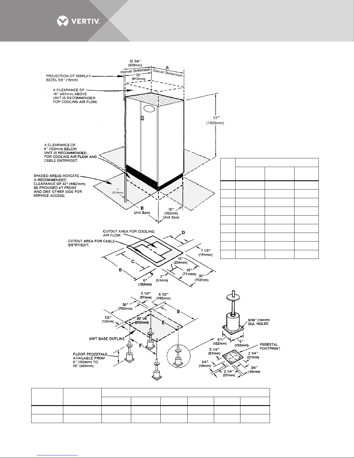
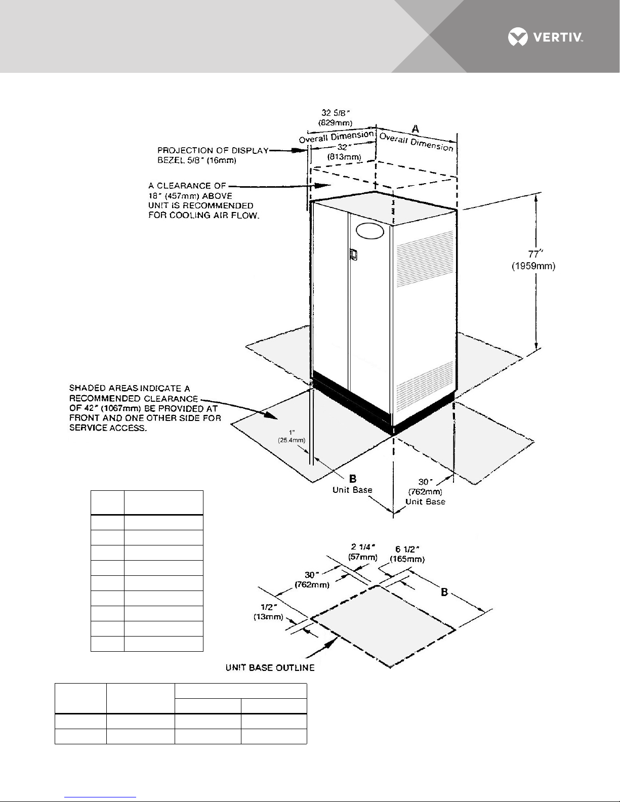
1.1.4 Location Considerations . . . . . . . . . . . . . . . . . . . . . . . . . . . . . . . . . . . . . . . . . . . . . . . . . . . . . . . . . . . . . . . . . . . . . . . . . . 6
1.1.5 Floor Pedestal Installation . . . . . . . . . . . . . . . . . . . . . . . . . . . . . . . . . . . . . . . . . . . . . . . . . . . . . . . . . . . . . . . . . . . . . . . . . 8
1.2 Distribution Sidecar Mounting and Wiring. . . . . . . . . . . . . . . . . . . . . . . . . . . . . . . . . . . . . . . . . . . . . . . . . . . . . . . . . 9
1.2.1 Sidecar Mounting . . . . . . . . . . . . . . . . . . . . . . . . . . . . . . . . . . . . . . . . . . . . . . . . . . . . . . . . . . . . . . . . . . . . . . . . . . . . . . . . . 9
1.2.2 Sidecar Electrical Connections . . . . . . . . . . . . . . . . . . . . . . . . . . . . . . . . . . . . . . . . . . . . . . . . . . . . . . . . . . . . . . . . . . . . 9
1.3 Power and Control Wiring . . . . . . . . . . . . . . . . . . . . . . . . . . . . . . . . . . . . . . . . . . . . . . . . . . . . . . . . . . . . . . . . . . . . . . . . 9
1.3.1 Input Power Connections . . . . . . . . . . . . . . . . . . . . . . . . . . . . . . . . . . . . . . . . . . . . . . . . . . . . . . . . . . . . . . . . . . . . . . . . 10
1.3.2 Junction Box Installation (If Used). . . . . . . . . . . . . . . . . . . . . . . . . . . . . . . . . . . . . . . . . . . . . . . . . . . . . . . . . . . . . . . . 20
1.3.3 System Grounding . . . . . . . . . . . . . . . . . . . . . . . . . . . . . . . . . . . . . . . . . . . . . . . . . . . . . . . . . . . . . . . . . . . . . . . . . . . . . . . 22
1.3.4 Grounding Electrode Conductor (Units With Transformer). . . . . . . . . . . . . . . . . . . . . . . . . . . . . . . . . . . . . . . . . 22
1.3.5 Output Power Connections. . . . . . . . . . . . . . . . . . . . . . . . . . . . . . . . . . . . . . . . . . . . . . . . . . . . . . . . . . . . . . . . . . . . . . . 24
1.3.6 Control Wiring Connections . . . . . . . . . . . . . . . . . . . . . . . . . . . . . . . . . . . . . . . . . . . . . . . . . . . . . . . . . . . . . . . . . . . . . . 26
1.3.7 Adapter Board . . . . . . . . . . . . . . . . . . . . . . . . . . . . . . . . . . . . . . . . . . . . . . . . . . . . . . . . . . . . . . . . . . . . . . . . . . . . . . . . . . . 30
2.0 EQUIPMENT INSPECTION AND STARTUP . . . . . . . . . . . . . . . . . . . . . . . . . . . . . . . . . . . . . .31
2.1 Internal Inspection . . . . . . . . . . . . . . . . . . . . . . . . . . . . . . . . . . . . . . . . . . . . . . . . . . . . . . . . . . . . . . . . . . . . . . . . . . . . . . .31
2.2 Startup . . . . . . . . . . . . . . . . . . . . . . . . . . . . . . . . . . . . . . . . . . . . . . . . . . . . . . . . . . . . . . . . . . . . . . . . . . . . . . . . . . . . . . . . . . 31
3.0 INSPECTION AND STARTUP CHECKLIST . . . . . . . . . . . . . . . . . . . . . . . . . . . . . . . . . . . . . 33
3.1 Inspection . . . . . . . . . . . . . . . . . . . . . . . . . . . . . . . . . . . . . . . . . . . . . . . . . . . . . . . . . . . . . . . . . . . . . . . . . . . . . . . . . . . . . . 33
3.2 Startup . . . . . . . . . . . . . . . . . . . . . . . . . . . . . . . . . . . . . . . . . . . . . . . . . . . . . . . . . . . . . . . . . . . . . . . . . . . . . . . . . . . . . . . . . 34
3.3 Monitoring System Check-Out. . . . . . . . . . . . . . . . . . . . . . . . . . . . . . . . . . . . . . . . . . . . . . . . . . . . . . . . . . . . . . . . . . . 35
3.4 Equipment Connection Check-Out (For Units With Distribution Cables) . . . . . . . . . . . . . . . . . . . . . . . . . . . 36
4.0 OPERATING INSTRUCTIONS . . . . . . . . . . . . . . . . . . . . . . . . . . . . . . . . . . . . . . . . . . . . . . . . . 37
4.1 Startup Procedures . . . . . . . . . . . . . . . . . . . . . . . . . . . . . . . . . . . . . . . . . . . . . . . . . . . . . . . . . . . . . . . . . . . . . . . . . . . . . 37
4.1.1 Emergency Shutdown. . . . . . . . . . . . . . . . . . . . . . . . . . . . . . . . . . . . . . . . . . . . . . . . . . . . . . . . . . . . . . . . . . . . . . . . . . . . 37
4.1.2 Normal System Shutdown. . . . . . . . . . . . . . . . . . . . . . . . . . . . . . . . . . . . . . . . . . . . . . . . . . . . . . . . . . . . . . . . . . . . . . . . 37
4.1.3 Normal System Turn ON . . . . . . . . . . . . . . . . . . . . . . . . . . . . . . . . . . . . . . . . . . . . . . . . . . . . . . . . . . . . . . . . . . . . . . . . . 37
4.1.4 Manual Restart . . . . . . . . . . . . . . . . . . . . . . . . . . . . . . . . . . . . . . . . . . . . . . . . . . . . . . . . . . . . . . . . . . . . . . . . . . . . . . . . . . 37
4.2 Basic Monitor Panel . . . . . . . . . . . . . . . . . . . . . . . . . . . . . . . . . . . . . . . . . . . . . . . . . . . . . . . . . . . . . . . . . . . . . . . . . . . . . 38
4.2.1 Display Controls and Indicators . . . . . . . . . . . . . . . . . . . . . . . . . . . . . . . . . . . . . . . . . . . . . . . . . . . . . . . . . . . . . . . . . . 38
4.3 Power Monitor Panel . . . . . . . . . . . . . . . . . . . . . . . . . . . . . . . . . . . . . . . . . . . . . . . . . . . . . . . . . . . . . . . . . . . . . . . . . . . . 39
4.4 Liebert Current Plus Monitoring (If Supplied) . . . . . . . . . . . . . . . . . . . . . . . . . . . . . . . . . . . . . . . . . . . . . . . . . . . . .41
4.5 Liebert Distribution Monitoring (If Supplied) . . . . . . . . . . . . . . . . . . . . . . . . . . . . . . . . . . . . . . . . . . . . . . . . . . . . . 43
5.0 MAINTENANCE . . . . . . . . . . . . . . . . . . . . . . . . . . . . . . . . . . . . . . . . . . . . . . . . . . . . . . . . . . . . . 45
5.1 Corrective Maintenance . . . . . . . . . . . . . . . . . . . . . . . . . . . . . . . . . . . . . . . . . . . . . . . . . . . . . . . . . . . . . . . . . . . . . . . . . 45
5.2 Preventive Maintenance (Inspection and Cleaning). . . . . . . . . . . . . . . . . . . . . . . . . . . . . . . . . . . . . . . . . . . . . . . 45

Vertiv |Liebert
®PPC™User Manual | Rev. 6 | 03/18 | ii
FIGURES
Figure 1 Typical cabinet and floor planning dimensions, sidecar . . . . . . . . . . . . . . . . . . . . . . . . . . . . . . . . . . . . . . . . .3
Figure 2 Typical cabinet and floor planning dimension data. . . . . . . . . . . . . . . . . . . . . . . . . . . . . . . . . . . . . . . . . . . . . 4
Figure 3 Typical cabinet and floor planning dimension data, top exit unit. . . . . . . . . . . . . . . . . . . . . . . . . . . . . . . . .5
Figure 4 Recommended minimum service and ventilation clearances . . . . . . . . . . . . . . . . . . . . . . . . . . . . . . . . . . . .7
Figure 5 Floor pedestal details . . . . . . . . . . . . . . . . . . . . . . . . . . . . . . . . . . . . . . . . . . . . . . . . . . . . . . . . . . . . . . . . . . . . . . . . .8
Figure 6 Electrical connection locations, sidecar unit . . . . . . . . . . . . . . . . . . . . . . . . . . . . . . . . . . . . . . . . . . . . . . . . . . . 11
Figure 7 Electrical connection location for 72-pole Square D or 54-pole GE panelboards, 32" cabinet,
bottom entry/exit . . . . . . . . . . . . . . . . . . . . . . . . . . . . . . . . . . . . . . . . . . . . . . . . . . . . . . . . . . . . . . . . . . . . . . . . . . . .12
Figure 8 Electrical connection locations, for 54-pole Square D or 42-pole GE panelboard, 32" cabinet,
bottom entry/exit . . . . . . . . . . . . . . . . . . . . . . . . . . . . . . . . . . . . . . . . . . . . . . . . . . . . . . . . . . . . . . . . . . . . . . . . . . . .13
Figure 9 Electrical connection location for 72-pole Square D or 54-pole GE panelboard, 44" cabinet,
bottom entry/exit . . . . . . . . . . . . . . . . . . . . . . . . . . . . . . . . . . . . . . . . . . . . . . . . . . . . . . . . . . . . . . . . . . . . . . . . . . . .14
Figure 10 Electrical connection locations, 54-pole Square D or 42-pole GE panelboard, 44" cabinet,
bottom entry/exit . . . . . . . . . . . . . . . . . . . . . . . . . . . . . . . . . . . . . . . . . . . . . . . . . . . . . . . . . . . . . . . . . . . . . . . . . . . .15
Figure 11 Electrical connection location for 54-pole Square D or 42-pole GE panelboard, 32" cabinet,
top entry/exit . . . . . . . . . . . . . . . . . . . . . . . . . . . . . . . . . . . . . . . . . . . . . . . . . . . . . . . . . . . . . . . . . . . . . . . . . . . . . . . .16
Figure 12 Electrical connection location for 72-pole Square D or 54-pole GE panelboard, 44" cabinet,
top entry/exit . . . . . . . . . . . . . . . . . . . . . . . . . . . . . . . . . . . . . . . . . . . . . . . . . . . . . . . . . . . . . . . . . . . . . . . . . . . . . . . .17
Figure 13 Typical junction box connections . . . . . . . . . . . . . . . . . . . . . . . . . . . . . . . . . . . . . . . . . . . . . . . . . . . . . . . . . . . . . 21
Figure 14 Typical grounding arrangements. . . . . . . . . . . . . . . . . . . . . . . . . . . . . . . . . . . . . . . . . . . . . . . . . . . . . . . . . . . . . 23
Figure 15 Typical Liebert PPC equipment arrangement. . . . . . . . . . . . . . . . . . . . . . . . . . . . . . . . . . . . . . . . . . . . . . . . . 25
Figure 16 Simplified shutdown circuit . . . . . . . . . . . . . . . . . . . . . . . . . . . . . . . . . . . . . . . . . . . . . . . . . . . . . . . . . . . . . . . . . . 26
Figure 17 Typical control wiring for units without monitoring . . . . . . . . . . . . . . . . . . . . . . . . . . . . . . . . . . . . . . . . . . . 27
Figure 18 Typical control wiring for units with power monitoring . . . . . . . . . . . . . . . . . . . . . . . . . . . . . . . . . . . . . . . . 28
Figure 19 Control wiring for units without low-voltage control box . . . . . . . . . . . . . . . . . . . . . . . . . . . . . . . . . . . . . . 29
Figure 20 Liebert PPC controls and indicators. . . . . . . . . . . . . . . . . . . . . . . . . . . . . . . . . . . . . . . . . . . . . . . . . . . . . . . . . . 38
TABLES
Table 1 Heat output. . . . . . . . . . . . . . . . . . . . . . . . . . . . . . . . . . . . . . . . . . . . . . . . . . . . . . . . . . . . . . . . . . . . . . . . . . . . . . . . . . .7
Table 2 Suggested minimum input wire size data. . . . . . . . . . . . . . . . . . . . . . . . . . . . . . . . . . . . . . . . . . . . . . . . . . . . . .18
Table 3 Main input circuit breaker interrupting rating. . . . . . . . . . . . . . . . . . . . . . . . . . . . . . . . . . . . . . . . . . . . . . . . . .19
Table 4 Main input junction box with transformer electrical connections . . . . . . . . . . . . . . . . . . . . . . . . . . . . . . 20
Table 5 Main input junction box without transformer electrical connections (5 wire) . . . . . . . . . . . . . . . . . . . 20
Table 6 Main input (power) junction box dimensions, typical . . . . . . . . . . . . . . . . . . . . . . . . . . . . . . . . . . . . . . . . . . 20
Table 7 Minimum grounding electrode conductor size (AWG). . . . . . . . . . . . . . . . . . . . . . . . . . . . . . . . . . . . . . . . . 22
Table 8 Panelboard main circuit breaker torque specifications . . . . . . . . . . . . . . . . . . . . . . . . . . . . . . . . . . . . . . . . 32
Table 9 Branch circuit breaker torque specifications. . . . . . . . . . . . . . . . . . . . . . . . . . . . . . . . . . . . . . . . . . . . . . . . . . 32
Table 10 Terminal block compression lug torque specifications . . . . . . . . . . . . . . . . . . . . . . . . . . . . . . . . . . . . . . . . 32
Table 11 Torque specifications, general . . . . . . . . . . . . . . . . . . . . . . . . . . . . . . . . . . . . . . . . . . . . . . . . . . . . . . . . . . . . . . . 32

Vertiv | Liebert®PPC™User Manual | Rev. 6 | 03/18 | 1
IMPORTANT SAFETY INSTRUCTIONS
Read this entire manual before installing or operating the system.
ELECTROMAGNETIC COMPATIBILITY—The Liebert PPC complies with the limits for a Class A digital device,
pursuant to Part 15 of FCC rules.
Operation is subject to the following conditions:
• This device may not cause harmful interference.
• This device must accept any interference received, including interference that may cause undesired operation.
Operating this device in a residential area is likely to cause harmful interference that users must correct at their
own expense.
The Liebert PPC complies with the requirements of EMC Directive 2014/30/EU and the published technical
standards. Continued compliance requires installation in accordance with these instructions and use of
accessories approved by Vertiv.
WARNING
Risk of cutting bands under tension. Can cause injury or death.
The shipping bands may be under tension. Use appropriate eye, face and hand protection to safeguard
against injury from band backlash.
WARNING
Risk of electric shock. Can cause injury or death.
Verify that all incoming line voltage (power) and low-voltage (control) circuits are de-energized and
locked out before installing cables or making connections, whether in the junction box or in the unit.
Equipment inspection and startup should be performed only by trained personnel. Lethal voltages are
present during startup procedures. Electrical safety precautions must be followed throughout inspection
and startup.
Only properly trained and qualified service personnel should perform maintenance on the Liebert PPC. All
voltage sources to the unit must be disconnected before inspecting or cleaning within the cabinet.
Lethal voltages exist within the equipment during operation. Observe all warnings and cautions in this
manual. Failure to comply may result in serious injury or death. Obtain qualified service for this equipment
as instructed.
The monitoring system contains a lithium battery for memory backup. Danger of explosion if battery is
incorrectly replaced. Replace only with same or equivalent type. Dispose of used batteries according to
manufacturer’s instructions.
WARNING
Risk of electric shock. Can cause injury or death.
All power and control wiring should be installed by licensed electricians and must comply with the NEC
and applicable codes.
WARNING
Risk of improper handling. Can cause equipment damage, injury or death.
The Liebert PPC is heavy; its weight ranges from 400lb. (182kg) to 2450lb. (1111kg) The unit should not
be loosened from the shipping pallet until after all handling by forklift or pallet jack is completed

Vertiv | Liebert®PPC™User Manual | Rev. 6 | 03/18 | 2
1.0 INSTALLATION INSTRUCTIONS
1.1 Unpacking and Installation
1.1.1 Unpacking and Preliminary Inspection
A high-quality installation begins on the receiving dock.
1. Inspect for damage or signs of mishandling before unpacking the unit(s). Check the Shock-Watch™indicator.
2. If the Liebert PPC was shipped in an export crate, open the shipping crate carefully. (Use care to avoid puncturing the
container with sharp objects that would damage the contents.)
3. Remove the packing and vapor barrier and inspect the equipment for any obvious shipping damages.
If any shipping damage is observed, immediately file a damage claim with the shipping agency and forward a
copy to:
Liebert Corporation
1050 Dearborn Drive
P.O. Box 29186
Columbus, Ohio 43229 USA
1.1.2 Handling Considerations
The Liebert PPC is bolted to a wooden pallet to allow handling by fork lift equipment.
Moving—The Liebert PPC sits on casters that allow the unit to be rolled into place after it has been unbolted
from the pallet.
Check size and weight—Refer to the cabinet drawings furnished with the unit for size and weight information.
Typical cabinet dimensions and weights are shown in Figures 1 and 2.
Plan the route—The route that the unit will follow to its installation area should be planned to ensure that all
passages are large enough to accommodate the unit, and that the floors are adequate to support the weight.
(For example: Are the doorway, elevators, ramps, etc., adequate? Are there any non-negotiable corners or offsets
in the hallways?)
Move with care—To prevent panel damage, Vertiv recommends removing the exterior panels before moving the
unit. Reconnect all panel ground wires when replacing panels.
NOTE
Read the entire manual before installing and operating the system. Upon receipt of a Liebert PPC, the installer
should perform the following steps to ensure a high-quality installation.
NOTE
The units should not be loosened from the shipping pallet until after all handling by fork lift or pallet jack is
completed. Complete internal inspection should be accomplished only after equipment positioning and prior to
electrical hookup.

Vertiv | Liebert®PPC™User Manual | Rev. 6 | 03/18 | 3
Figure 1 Typical cabinet and floor planning dimensions, sidecar
18"
(457mm)
1-14"
(32mm)
30"
(762mm)
23-7/8"
(733 mm)
1/2"
(13mm)
Unit Base
Outline
Floor Pedestals
Available from 6"-19"
(152mm to 483mm)
9/16" (14mm)
Dia. Holes
2-1/4"
(57mm)
2-1/4"
(57mm)
2-1/4"
(57mm)
3/4"
(19mm)
3/4"
(19mm)
6"
(152mm) 6" (152mm)
2"
(50mm)
4"
(102mm)
18" (457 mm)
10"
(254 mm)
30" (762mm)
12"
(305mm)
22"
(559mm)
7"
(178mm)
20"
(508mm )
Overall
Dimension
18"
(457mm)
Unit Base
Pedestal
Footprint
Shaded areas indicate
recommended clearance
of 42" (1067mm) at front
and one other side for
service access.
Clearance of 6"
(152mm) below unit is
recommended for
cooling airflow and
cable exit .
Clearance of 18"
(457mm) above unit is
recommended for
cooling airflow .
Cutout area for
cable exit and
cooling airflow .
77"
(1959mm)
32"
(813 mm)
1"
(25.4mm)
30"
(762 mm)
Unit Base
Optional Floor
Pedestals
Footprint and Floor
Cutout Dimensions
Cabinet Dimensions
The Liebert EXC weighs 300 lb. (136kg)

Vertiv | Liebert®PPC™User Manual | Rev. 6 | 03/18 | 4
Figure 2 Typical cabinet and floor planning dimension data
Unit kVA
No. of
Panelboards
Dimensions, in. (mm)
ABCDEF
15 to 125 1 32 (813) 30 (762) 18 (457) 15 (381) 17 (432) 29 (737)
150 to 225 2 44 (1118) 42 (1067) 30 (762) 27 (686) 29 (737) 41 (1041)
Unit
kVA
Weight, lb. (kg)
60 Hz 50 Hz
Without
Xfmr
15 650 (295) 700 (318) 400 (182)
30 750 (340) 800 (363) 400 (182)
50 898 (408) 925 (420) 400 (182)
75 1115 (507) 1150 (522) 400 (182)
100 1275 (579) 1400 (635) 450 (204)
125 1450 (658) 1575 (715) 450 (204)
150 1789 (813) 1900 (862) 700 (318)
200 2110 (959) 2300 (1043) 700 (318)
225 2353 (1070) 2450 (1111) 700 (318)
Add 50 lb. (14kg) to 50 thru 125 kVA units in 44"
cabinet.
CABINET DIMENSIONS
Footprint and Floor
Cutout Dimensions
Optional Floor
Pedestals

Vertiv | Liebert®PPC™User Manual | Rev. 6 | 03/18 | 5
Figure 3 Typical cabinet and floor planning dimension data, top exit unit
Unit kVA
No. of
Panelboards
Dimensions, in. (mm)
AB
15-125 1 32 (813) 30 (762)
150-225 1 44 (1118) 42 (1067)
Footprint Dimensions
CABINET DIMENSIONS
Unit
kVA Weight, lb. (kg)
15 650 (295)
30 750 (340)
50 950 (432)
75 1165 (530)
100 1325 (601)
125 1500 (680)
150 1789 (813)
200 2110 (959)
225 2353 (1070)

Vertiv | Liebert®PPC™User Manual | Rev. 6 | 03/18 | 6
1.1.3 Unit Preparation
The Liebert PPC may be removed from the shipping pallet and installed by customer personnel. A typical
procedure is:
1. Set the palletized assembly in a level area, where there is enough room to roll the unit and entire cable assembly off the
pallet onto the floor.
2. Cut the shipping bands.
3. Remove the factory-provided ramp from its shipping position—packed in front of the unit. Place the ramp adjacent to the
pallet to provide a smooth path from pallet to floor.
4. Remove side and rear panels from the module. An Allen wrench for the side panels is furnished in the installation packet.
(Carefully disconnect panel ground wires by pulling the easy-disconnect terminals at the unit frame.)
5. Remove the bolts holding the unit to the shipping pallet. (Located in each of the four bottom corners.)
6. Remove shipping blocks from under unit, then remove chocks from all casters.
7. Roll unit off pallet onto floor.
8. Roll unit to its installation location. For units located on a raised floor, use care when positioning unit over the floor cutout
to avoid casters falling through the cutout.
1.1.4 Location Considerations
The Liebert PPC should be located within the computer room, and/or close to the load(s) which it is supplying.
Equipment Location—Should employ the shortest output distribution cable runs consistent with logical
equipment arrangement and allowances for future additions.
Operating Environment—Ambient temperatures of 32°F to 104°F (0°C to 40°C) with a relative humidity of 0%
to 95% (non-condensing).
Bottom Clearance—Required for exit of cables/conduit and/or for cooling air flow. This clearance is
automatically provided by a raised floor (6 in. / 150 mm minimum height). Figures 1 and 2show typical
raised-floor cutout dimensions.
When units are not located on a raised floor (or if the raised floor is not adequate to support the unit), optional
floor pedestals may be used. (Non-raised floor applications are not CSA approved.) Units with top cable exit
provisions and side vents do not require bottom clearance.
Recommended Minimum Service Clearances—Shown in Figure 4. The indicated clearances at the front and
one other side or rear of the unit are required for service access by the National Electrical Code (NEC)
(Article 110-26). Clearance above the unit is required for cooling air flow (exhaust).
Heat Output—As do all electrical devices, the Liebert PPC produces heat under normal operation. (See Table 1.)
This heat output should be included when calculating the environmental conditions of the room.
WARNING
Risk of cutting bands under tension. Can cause injury or death.
The shipping bands may be under tension. Use appropriate eye, face and hand protection to safeguard
against injury from band backlash.
NOTE
Before maneuvering the unit into its final position, read and follow all advisories in the following paragraphs in
1.1.4 - Location Considerations.

Vertiv | Liebert®PPC™User Manual | Rev. 6 | 03/18 | 7
Figure 4 Recommended minimum service and ventilation clearances
Table 1 Heat output
Full Load Heat Output, BTU/hr (kW)
kVA BTU/hr (kW)
15 1915 (0.56)
30 3995 (0.88)
50 4360 (1.28)
75 6140 (1.80)
100 7680 (2.25)
125 9460 (2.77)
150 10,660 (3.13)
200 13,930 (4.08)
225 15,350 (4.45)
18 in. (457mm)
minimum clearance
above unit for
cooling air flow
ADDITIONAL ACCESS ON EITHER
SIDE OR THE REAR OF UNIT - see
Notes 1 and 2
6 in. (152 mm) minimum
clearance below unit for
bottom cable exit
NOTES:
1. Service access is required at the front, plus one other side or rear.
2. Service access clearance:
36 in. (914 mm) for units up to 150 volts to ground
42 in. (1067 mm) for units over 150 volts to ground
FRONT ACCESS REQUIRED
See Notes 1 and 2
See Note 2
See Note 2 See Note 2

Vertiv | Liebert®PPC™User Manual | Rev. 6 | 03/18 | 8
1.1.5 Floor Pedestal Installation
Floor pedestals are optional equipment intended to provide clearance for bottom cable entry without relying on
a raised floor to support the unit. The pedestals are adjustable over approximately 3-1/2 in. (89mm) to allow
leveling the unit and minor adjustments in the unit’s installed height.
1. Insert the pedestal threaded shaft into the inside corner tubing of the cabinet base as shown in Figures 1 and 2.
2. Adjust the pedestal height by turning the welded nut/shaft assembly into or out of the pedestal base as required.
3. Lock the height by tightening the jam nut against the pedestal base.
The pedestal may be secured to the floor by means of the four holes in the base. Locations of floor pedestals are
shown in Figures 1 and 2.
Figure 5 Floor pedestal details
NOTE
Floor pedestals may be reverse-assembled for shipping. Before installation, reassemble the pedestals as shown
in Figure 5. When the pedestal is properly assembled, the washer on top of the welded nut provides a bearing
surface for the unit’s weight.
6"
(152mm)
square
2-1/4"
(57mm)
2-1/4"
(57mm)
2-1/4"
(57mm)
2-1/4"
(57mm)
9/16" (14mm)
diameter
mounting holes
Pedestal
Base
Jam Nut
Welded Nut
Washer
Threaded
Shaft
3"
(76mm)

Vertiv | Liebert®PPC™User Manual | Rev. 6 | 03/18 | 9
1.2 Distribution Sidecar Mounting and Wiring
For Liebert PPC units with more than two panelboards, the additional panelboards are furnished in side-mounted
enclosures that are shipped separate from the main unit.
1.2.1 Sidecar Mounting
The additional distribution sidecar is 18 in. x 30 in. (457x762mm) and can be mounted on either the left or right
side of the main unit, with left side mounting recommended.
1. Provide a floor cutout for exit of output cables, as shown in Figure 1.
2. Remove the side panel, the upper panel retainers and the lower panel hooks from the main unit.
3. Align the distribution sidecar with the main unit and bolt the two frames together using the four bolts and hardware
provided.
4. If floor pedestals are used for the main unit, two additional floor pedestals are required for the outside corners of the
sidecar. See Figure 1.
5. Install the upper panel retainers and lower panel hooks on the sidecar enclosure.
6. After electrical connections are completed, install the unit side panel on the sidecar.
1.2.2 Sidecar Electrical Connections
Five conductors (3-phase conductors, neutral and ground) are furnished with the distribution sidecar for
connection to the main unit in the field, along with an intercabinet frame ground conductor.
For Liebert PPC’s with transformers, the sidecar phase conductors are connected directly to the transformer
terminals:
• Phase A (wire 412) to X1
• Phase B (wire 422) to X2
• Phase C (wire 432) to X3
The sidecar neutral (Wire 442) and ground (Wire 452) conductors are connected to the Liebert PPC main
ground busbar (see unit wiring diagram).
For Liebert PPC’s without transformers, the sidecar phase and neutral conductors are connected to the
corresponding output power distribution terminal blocks inside the main unit. The sidecar ground conductor is
connected to the main ground busbar.
For all Liebert PPC’s with VPMP monitoring, route each sidecar conductor through the appropriate current
transformer (CT) in the main unit.
1.3 Power and Control Wiring
Power and control wiring should be installed by licensed electricians. All power and control wiring must comply
with the NEC and applicable local codes.
NOTE
Sidecar conductors must pass through the current transformers in the same direction as the main unit
panelboard conductors. Use the existing main unit panelboard wiring for reference.

Vertiv | Liebert®PPC™User Manual | Rev. 6 | 03/18 | 10
1.3.1 Input Power Connections
If the unit is furnished with junction boxes, input power connections are made as detailed in 1.3.2 - Junction Box
Installation (If Used).
If junction boxes are not furnished, the input power feeder is connected to the input power lugs or blocks located
inside the unit. (See Figures 6, 8, and 10.)
To minimize disturbances caused by other loads in the building, the 3-phase power input to the unit should be
supplied directly from the service entrance or other power source (a dedicated power feeder).
The input feeder circuit should be sized in accordance with the NEC and any local building codes to assure the
feeder’s ability to safely carry the system’s full load current, including losses.
Input feeder conductors should be sized for no more than 2% voltage drop. If operation at undervoltage
conditions for extended periods of time is desired, the input feeders must be oversized.
Typical conductor size data is shown in Table 2. All connections must comply with the NEC and all other
applicable codes.
For units with a transformer, the main input feeder should consist of 3-phase conductors and one (safety)
ground conductor (3W + G).
For units without a transformer, the main input feeder must consist of 3-phase conductors, one neutral and
one (safety) ground conductor (4W + G).
WARNING
Risk of electric shock. Can cause injury or death.
Verify that all incoming line voltage (power) and low-voltage (control) circuits are de-energized and
locked out before installing cables or making connections, whether in the junction box or in the unit.

Vertiv | Liebert®PPC™User Manual | Rev. 6 | 03/18 | 11
Figure 6 Electrical connection locations, sidecar unit
Neutral Connections
Distribution Cables Neutral(s)
connected to distribution
panelboard neutral busbar
Panelboard Main Circuit Breaker
Factory-Wired
Distribution Panelboard
Distribution Cable Conduit Connection
Cable Tray 1-3/32" (27.8mm) holes for
3/4" conduit fittings and 7/8" (22.2mm)
holes for 1/2" conduit fittings provided for
securing optional distribution cables
Ground Connections
Distribution Cable Ground(s)
connected to distribution
panelboard ground busbar
Interconnection Wiring
provided by factory
NOTES
1. The unit bolts to the main
Liebert Precision Power Center. See
installation manual for instructions.
2. Site panel is taken from the Liebert PPC
and installed to either the left or right side
of the unit.
FRONT VIEW WITH DOOR OPEN
AND PANEL REMOVED
PPC15010
Rev. 2

Vertiv | Liebert®PPC™User Manual | Rev. 6 | 03/18 | 12
Figure 7 Electrical connection location for 72-pole Square D or 54-pole GE panelboards, 32" cabinet, bottom entry/exit
PPC15100
Rev. 0

Vertiv | Liebert®PPC™User Manual | Rev. 6 | 03/18 | 13
Figure 8 Electrical connection locations, for 54-pole Square D or 42-pole GE panelboard, 32" cabinet, bottom entry/exit
Ground Connections
Distribution Cables
Ground(s) connected
to distribution panelboard
ground busbar
Distribution Cable
Conduit Connection
Cable tray 1-3/32" (27.8mm)
holes for 3/4" conduit fittings
and 7/8" (22.2mm) holes
for 1/2" conduit fittings
provided for securing
optional distribution cables. Front View
Without Doors
Optional Subfeed
Breaker
(See Detail D)
Distribution
Panelboard
Input Cable
Conduit
Connections
Rear View
Without Doors
PPC15101
Rev. 0
Ground Electrode
Conductor Connection
Customer connection of
continuous ground electrode
conductor. Not needed on
systems without transformer.
Safety Ground Connection
For units without main input
junction box, customer connection
of main input safety ground
conductor. (See Detail C)
Main Input Neutral Connection
For units without isolation
transformer and without main
input junction box, customer
connection of main input neutral
conductor. (See Detail B)
Detail D
Subfeed Circuit Breaker
3-phase Connections
Busbars for 2-hole lugs
(1-3/4" spacing) with ø0.563
hole. Connect ground and
neutral wires to main ground
and neutral busbars
Panelboard Main
Circuit Breaker
Factory-Wired
Optional Subfeed Breaker
(See Detail D)
Main Input Power Connection
For units without main input junction box.
Busbars for 2 hole lugs (1 3/4" spacing)
with 0.563" dia. holes are provided at line
side terminals of main input circuit breaker
for customer connection of 3-phase power
(See Detail A)
1.25"
(32mm) ø0.375" (10mm)
1.25"
(32mm)
0.437" sq. (11mm)
(6 Places)
ø0.563" (14mm)
(6 Places)
Detail C
Ground Busbar
1.75"
(44mm)
1.50"
(38mm)
0.437" sq.
(11mm)
(7 Places)
ø0.563" (14mm)
(8 PLACES)
Detail B
Neutral Busbar
1.25"
(32mm)
1.74"
(44mm)
1.50"
(38mm)
Detail A
Input Circuit Breaker
Neutral Connections
Distribution Cables
Neutral(s) connected
to distribution panelboard
neutral busbar

Vertiv | Liebert®PPC™User Manual | Rev. 6 | 03/18 | 14
Figure 9 Electrical connection location for 72-pole Square D or 54-pole GE panelboard, 44" cabinet, bottom entry/exit
PPC15102
Rev. 0

Vertiv | Liebert®PPC™User Manual | Rev. 6 | 03/18 | 15
Figure 10 Electrical connection locations, 54-pole Square D or 42-pole GE panelboard, 44" cabinet, bottom entry/exit
REAR VIEW
Without Doors and Access Panels
Main Input Neutral Connection
For units without isolation
transformer and without main
input junction box, customer
connection of main input neutral
conductor. (See Detail B).
Safety Ground Connection
For units without main input
junction box, customer connection
of main input safety ground
conductor. (See Detail C).
Ground Electrode
Conductor Connection
Customer connection of
continuous ground electrode
conductor. Not needed on
systems without transformer.
DETAIL D
Subfeed Circuit Breaker
3-Phase Connections
Busbars for 2-hole lugs
(1 3/4" spacing) with ø0.563"
hole. connect ground and
neutral wires to main ground
and neutral busbars.
ø0.375"
(10mm)
1.25"
(32mm)
0.437" SQ. (11mm)
(6 Places)
ø0.563" (14mm)
(6 Places)
1.25"
(32mm)
DETAIL C
Ground Busbar
1.75"
(44mm)
1.50"
(38mm)
1.25"
(32mm)
1.75"
(44mm)
1.50"
(38mm)
0.437" sq.
(11mm)
(7 Places)
ø0.563"
(14mm)
(8 Places)
DETAIL B
Neutral Busbar
Main Input Power Connection
For units without main input junction box, busbar
for 2-hole lugs (1 3/4" spacing) with 0.563" dia. holes
are provided at line side terminals of main input circuit breaker
for customer connection of 3-phase power (See Detail A)
Subfeed Circuit Breakers (Optional
(See Detail B)
DETAIL A
Input Circuit Breaker
Neutral Connections
Distribution cables
neutral(s) connected to
distribution panelboard
neutral busbar.
Ground Connections
Distribution cable
ground(s) connected to
distribution panelboard
ground busbar.
Panelboard Main
Circuit Breaker
Factory-Wired
Distribution
Panelboard
Distribution Cable
Conduit Connection
Cable Tray 1-3/32" (27.8mm)
Holes for 3/4" conduit fittings
and 7/8" (22.2mm) holes
for 1/2" conduit fittings
provided for securing
optional distribution cables.
Input Cable
Conduit Connections
FRONT VIEW
Without Doors and Access Panels
PPC15103
Rev. 0

Vertiv | Liebert®PPC™User Manual | Rev. 6 | 03/18 | 16
Figure 11 Electrical connection location for 54-pole Square D or 42-pole GE panelboard, 32" cabinet, top entry/exit
Detail A
Input Circuit Breaker
Input Cable
Conduit Connections
Neutral Connections
Distribution Cables
Neutral(s) connected
to distribution panelboard
neutral busbar
Ground Connections
Distribution Cables
Ground(s) connected
to distribution panelboard
ground busbar
Front View
Without Doors and Access Panels
Distribution Panelboard
Main Input Power Connection
For units without main input junction box,
bus bar for 2 hole lugs (1 3/4" spacing)
with 0.563" dia. holes are provided at line
side terminals of main input circuit breaker
for customer connection of 3-phase power
(See Detail A)
Panelboard Main Circuit Breaker
Factory-Wired
Distribution Cable
Conduit Connection
Cable tray 1 3/32" (27.8mm) holes for
3/4" conduit fittings and 7/8" (22.2mm)
holes for 1/2" conduit fittings provided
for securing optional distribution cables
ø0.375"
(10mm)
1.25" (32mm)
0.437" sq.
(11mm)
(6 places)
ø0.563"
(14mm)
(6 places)
1.25"
(32mm)
Detail C
Ground Busbar
1.75"
(44mm)
1.50"
(38mm)
1.25"
(32mm)
1.75"
(44mm)
1.50"
(38mm)
0.437" sq.
(11mm)
(7 places)
ø0.563"
(14mm)
(8 places)
Detail B
Neutral Busbar
Main Input Neutral Connection
For units without isolation
transformer and without main
input junction box, customer
connection of main input neutral
conductor. (See Detail B)
Safety Ground Connection
For units without main input
junction box, customer connection
of main input safety ground
conductor. (See Detail C)
Ground Electrode
Conductor Connection
Customer connection of
continuous ground electrode
conductor. Not needed on
systems without transformer.
Rear View
Without Doors and Access Panels
PPC15121
Rev. 0
Table of contents
Popular AC Power Distribution manuals by other brands

APT
APT 310XAC quick start guide

cyber Switching
cyber Switching Dualcom installation instructions

Torus Power
Torus Power IS 5 RK owner's manual

Tripp Lite
Tripp Lite isobar DL510PC owner's manual

B+K precision
B+K precision 9801 Programming manual

FRONIUS
FRONIUS TransSynergic 5000 Operating instructions & spare parts