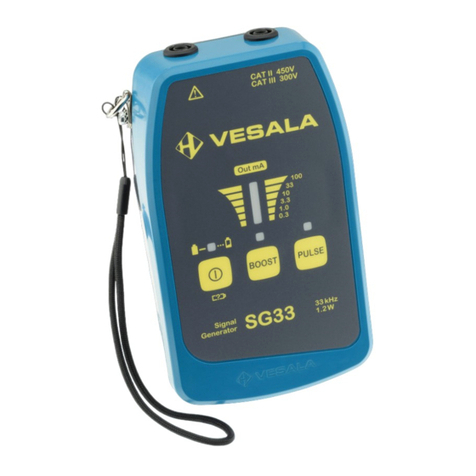
VESALA CL43 User manual

User Manual
Vesala CL43 X2.1 ENG
for Vesala CL43 Compact Locator version X2.1
combined with at least one of the following
antennas: SA43, SA05, LA43 or KA43
IMPORTANT: Read carefully before use.
Keep for future reference.
English
Issued: 2021-03-17
Revised: 2021-08-26

User Manual Vesala CL43 X2.1 ENG
2 (28)
Table of contents
1
Safety notes ................................................................................................................................................................................... 3
2
General description ..................................................................................................................................................................... 5
2.1
Intended use ........................................................................................................................................................................ 5
2.2
Specifications ...................................................................................................................................................................... 5
2.3
Package contents ............................................................................................................................................................... 9
2.4
Removing and inserting batteries .............................................................................................................................. 10
2.5
Inserting and removing antennas .............................................................................................................................. 11
2.6
CL43 parts and functions............................................................................................................................................... 12
3
Operating CL43 Compact Locator........................................................................................................................................ 13
3.1
Using antennas ................................................................................................................................................................. 13
3.2
Locating ducts with a sonde ........................................................................................................................................ 14
3.3
Using signal generators ................................................................................................................................................. 17
3.4
Locating buried cables ................................................................................................................................................... 18
3.5
Locating cables and wires at a short distance ........................................................................................................ 19
3.6
Locating cable faults ....................................................................................................................................................... 20
3.7
Identifying circuit breakers, switches and fuses in low voltage network ..................................................... 21
3.8
Locating and identifying open ends of wires ......................................................................................................... 22
4
Taking care of your equipment ............................................................................................................................................. 23
4.1
Storing ................................................................................................................................................................................. 23
4.2
Cleaning .............................................................................................................................................................................. 23
4.3
Troubleshooting ............................................................................................................................................................... 24
4.4
Maintenance ...................................................................................................................................................................... 26
4.5
Modifying and misuse .................................................................................................................................................... 27
4.6
Warranty.............................................................................................................................................................................. 27
4.7
Disposal ............................................................................................................................................................................... 27
5
Supplier contact information ................................................................................................................................................. 28
6
Declaration on conformity ...................................................................................................................................................... 28

3 (28)
User Manual Vesala CL43 X2.1 ENG
1 Safety notes
To avoid possible harm, read and follow these instructions.
DANGER: Risk of electric shock, fire or property damage
The outer surface of CL43 Compact Locator is electrically conductive. Touching hazardously live
circuits with CL43 Compact Locator may result in an injury or death. Dropping or placing CL43
Compact Locator on a live circuit may result in a short circuit, fire or property damage. Do not
use CL43 Compact Locator near exposed, hazardously live circuits.
DANGER: Risk of electric shock or fire
Circuits may be misidentified of mislabeled. Always test circuits for hazardous voltages before
performing operations on them.
CAUTION: Referring to the documentation needed
When identifying circuits in certain electromagnetic conditions, CL43 Compact Locator may
give a false positive indication or may fail to give a correct indication. Refer to instructions for
use to learn how to properly identify circuits with CL43 Compact Locator.
In the event of electric shock
1. Quickly assess the situation.
2. Turn off the power if possible.
3. Disconnect the patient from the supply with an insulating object if necessary.

User Manual Vesala CL43 X2.1 ENG
4 (28)
4. Assess the condition of the patient.
5. Alert emergency responders if necessary.
6. Give CPR if necessary.
7. Direct emergency responders to the patient.
8. Prevent further injuries by informing others about the accident.
9. Always seek medical attention.
In the event of fire
1. Quickly assess the situation.
2. Turn off the power if possible.
3. Alert others in danger.
4. Alert emergency responders if necessary.
5. Try to put out the fire if possible.
6. Contain the fire if possible.
7. Direct emergency responders to the location.
In the event of property damage
1. Quickly assess the situation.
2. Turn off the power if possible.
3. Prevent further damage by informing others about the accident.
4. Repair or replace damaged property.

5 (28)
User Manual Vesala CL43 X2.1 ENG
2 General description
2.1 Intended use
CL43 Compact Locator is a hand held 512 Hz and 33 kHz receiver which can be used indoors or
outdoors. When used with one or more signal generators CL43 Compact Locator can locate and
identify cables, wires, circuit breakers, switches, fuses and cable faults. Together with a sonde
CL43 Compact Locator can locate and identify ducts, pipes, cavities and their blockages. CL43
Compact Locator is always used combined with a separate dedicated antenna which is selected
according to located object and work environment.
2.2 Specifications
I/O ports One male 3-pin XLR for dedicated antennas
Operating frequencies 512 Hz
32768 Hz
Ambient temperature -10°C…+40°C
Humidity 0…90 % RH
Storage conditions,
batteries installed +5°C…+30°C
10...90 % RH, non-condensing

User Manual Vesala CL43 X2.1 ENG
6 (28)
Storage conditions,
batteries removed -20°C…+40°C
10...90 % RH, non-condensing
Degree of protection IEC 60529: IP44
LED-indicators Green power LED with low battery warning
Red 12-level LED arc display for receiving signal strength, battery
voltage, firmware version and receiving frequency
Audio output Internal waterproof speaker
Batteries 3 pcs 1.5 V IEC LR03
Current consumption 15...60 mA
Nominal battery
voltage 4.5 V
Operating voltage
range 3.6...6.5 V
Enclosure Stainless steel, aluminium and polyamide, 180 x Ø46 mm
Weight 232 g with LR03 batteries, no antennas attached

7 (28)
User Manual Vesala CL43 X2.1 ENG
International standards
this product is in
conformance with
EN 301 489-1 V2.2.3
EN 301 489-3 V2.1.1
EN 303 454 V1.1.1
EN 61010-1:2010/A1:2019/AC:2019-04
EN IEC 63000:2018
Electromagnetic
environment ETSI EN 301 489-1
Residential, commercial and light industrial environment
Primary function type ETSI EN 301 489-3
III: Others
Device type ETSI EN 301 489-3
3: Standard reliable SRD communication media; e.g.
inconvenience to persons, which can simply be overcome by other
means (e.g. manual)
Receiver category ETSI EN 301 489-3
2
User control functions
and stored data Gain setting in 7 or 5 steps depending on antenna,
10 dB/step
Type of modulation Continuous wave or 100 % AM @ <10 Hz

User Manual Vesala CL43 X2.1 ENG
8 (28)
Supported dedicated
antennas SA05: H-field antenna for 512 Hz, 156 x 23 x 20 mm, weight 105 g,
green part is insulated, effective range up to 10 m
SA43: H-field antenna for 32768 Hz, 156 x 23 x 20 mm,
weight 90 g, black tip is insulated up to white label, effective range
up to 10 m
LA43: H-field proximity antenna for 32768 Hz, 73 x 35 x 35 mm,
weight 70 g, black cylindrical part is insulated up to white label,
effective range when locating cables up to 30 cm or up to 2 m
when locating sondes
KA43: E-field antenna for 32768 Hz, 90 x 23 x 20 mm, weight 30 g,
red part is insulated, effective range up to 30 cm

9 (28)
User Manual Vesala CL43 X2.1 ENG
2.3 Package contents
The following items are supplied in the package.
CL43 Compact Locator receiver (V11360)
Version number is indicated at the beginning of the serial number.
1.5 V alkaline battery LR03 (J01573), 3 pcs
One or more of the following four antennas are supplied depending on chosen kit. Selecting
suitable antenna for each task is the most important part of locating. Antenna type is indicated
at the antenna connector.
SA43 Rod antenna (V14306), black, for locating
buried cables with a 33 kHz signal generator or
locating non-conductive ducts with 33 kHz sondes
SA05 Rod antenna (V14308), green, for locating
conductive ducts made of cast iron or stainless
steel, or non-conductive ducts with 512 Hz sondes
KA43 Capacitive antenna (V14320), red, for identifying exposed
open wires, wire pairs or single wires with a 33 kHz signal
generator

User Manual Vesala CL43 X2.1 ENG
10 (28)
LA43 Proximity antenna (V14310), black. Use with a 33 kHz signal
generator: for identifying exposed cables, looped wires, circuit breakers,
switches and fuses, locating cables in tight spaces, locating cables and cable
faults under or inside a surface such as a floor or a wall. Use with a 33 kHz
sonde: for locating non-conductive ducts with larger sondes, pinpointing
sondes inside exposed non-conductive ducts
Additional antennas or spares may be purchased separately. Other accessories or devices may
be sold together with CL43 Compact Locator or included in the kit. Refer to their corresponding
information for use.
2.4 Removing and inserting batteries
Turn the user interface cap anti-clockwise
and pull the battery holder out. Remove
old batteries. Insert three new LR03 (AAA)
alkaline batteries. Observe battery
polarity: place negative poles against the
spring contacts. Insert the battery holder
arrow end first back into the receiver unit.
Turn the user interface cap clockwise until
it stops.

11 (28)
User Manual Vesala CL43 X2.1 ENG
2.5 Inserting and removing antennas
CL43 Compact Locator always requires an
antenna to operate. Choose antenna
according to the locating task. To attach
an antenna, push the antenna connector
(1) into socket (2) aligned as in the image
until the latch clicks. To remove an
antenna: Press the antenna release
button (3) under the rubber to release the
latch and pull the antenna out. Antennas
are water and dust protected only when
connected to the receiver unit. If an antenna is wet or dirty, dry and clean it before removing the
antenna in order to avoid dirt and water getting inside the connector.

User Manual Vesala CL43 X2.1 ENG
12 (28)
2.6 CL43 parts and functions
Plus key Antenna
Long press: toggle power on or off
Short press: increase sensitivity
Extended start-up press: display firmware version Antenna release button
Releasing after start-up:
display battery voltage and receiving frequency
Minus key Receiver
Decrease sensitivity
Batteries User interface cap
Located under the user interface cap: 3 x 1.5 V LR03
LED arc
Indicates received signal strength.
The 512 and 33k LEDs display the receiving frequency
after antenna insertion.
Power LED
Green LED indicates power on. LED blinks if batteries are weak.
Speaker
Indicates received signal strength;
the higher the pitch and volume, the stronger the signal.

13 (28)
User Manual Vesala CL43 X2.1 ENG
3 Operating CL43 Compact Locator
3.1 Using antennas
SA43 Rod antenna or SA05 Rod antenna is typically used by pointing it towards the
approximate direction of a buried or hard-to-reach target cable, wire or duct. A very narrow and
accurate signal minimum, also called signal null, can often be detected exactly in the direction
of the target accompanied by a maximum both sides of this null. This is called the minimum
locating method. Rod antennas are very sensitive and lowering the sensitivity is usually needed
when approaching the target. If strong interfering magnetic field from a stationary source
prevents operation, rod antennas can be rotated to an angle which effectively cancels the
interference. Such sources include power lines, wiring and heavy equipment in an industrial site,
electric trains, subways and trams including their tracks and wiring. When the target is exposed
and accessible, it is usually easier to use a proximity antenna.
LA43 Proximity antenna has a flat, round, insulated bottom which is set or moved on the
target surface, duct, wire, cable or cable bunch. A narrow signal minimum can often be detected
right above the target, especially if the distance is short. If the target surface is sensitive it is
recommended to use a piece of soft cloth between the antenna and the surface to prevent
scratches. Although a proximity antenna is relatively insensitive to distant sources of
interference, its limited range makes it ineffective when locating buried cables or ducts with the
smallest sondes. In those cases, use a rod antenna instead.

User Manual Vesala CL43 X2.1 ENG
14 (28)
KA43 Capacitive antenna is typically moved above exposed wires or wire pairs, or above wire
terminals. The very tip of the antenna is the active point which senses the signal generator
voltage on the target. A looped, shorted or loaded wire cannot be detected with a capacitive
antenna. Use a proximity antenna in those cases.
3.2 Locating ducts with a sonde
Sonde is a small, independent transmitter device that generates a magnetic field which
oscillates at a specific frequency depending on the sonde type. Ducts, pipes, tubes, cavities or
their blockages can be located by inserting a sonde inside of them and then locating the sonde.
Objects made of a non-conductive material can be located with a 33 kHz sonde and either Rod
antenna SA43 or a Proximity antenna LA43. Conductive ducts made of cast iron or stainless steel
should be located with a 512 Hz sonde and SA05 Rod antenna making use of their low
frequency which penetrates these materials.
Approximate location: Hold the CL43 in 45°
angle. Scan left and right with the antenna and
move to the direction where the signal gets
stronger in average. Location accuracy of
approximately 1 m can be achieved by this
method.

15 (28)
User Manual Vesala CL43 X2.1 ENG
Exact longitudinal location: Hold CL43 vertically
and approach the sonde in the duct. To define
exact longitudinal location of the sonde, pinpoint
signal minimum line. It runs transversely (90°)
against the direction of the duct. Mark the
minimum line to the ground.
Exact transversal location: Turn CL43 to
horizontal position and hold it transversely (in 90°
angle) above the minimum line. Keep the antenna
in this position and height and move left and right
on the minimum line to find the strongest signal
you can get. Signal peak pinpoints the exact sonde
location underground.

User Manual Vesala CL43 X2.1 ENG
16 (28)
Sonde depth: Hold the CL43 horizontally
and transversely (in 90° angle) to the
minimum line. Move CL43 further ahead
to the sonde nose direction until another
minimum is detected. Sonde depth h is
the distance s of the two minimums
multiplied by 1.4.
Cancelling interference: To locate a
sonde close to an interfering cable, duct or
rail with a rod antenna: Rotate CL43
parallel to the source of interference
(usually horizontal) thus minimizing its
effect. Keep this attitude and move CL43
towards the sonde until a signal maximum
is detected.

17 (28)
User Manual Vesala CL43 X2.1 ENG
3.3 Using signal generators
A cable locator detects the magnetic or electric field which has
been induced to a cable or wire using a signal generator. Locating
is often affected by other nearby conductors and ducts. In order to
use a signal generator with CL43, select a signal generator that
outputs 33 kHz (32768 Hz) frequency. For safe and proper
connection refer to signal generator information for use.

User Manual Vesala CL43 X2.1 ENG
18 (28)
3.4 Locating buried cables
Connect a signal generator between the located cable and ground or use an inductive coupler.
Use SA43 Rod antenna to track the cable route starting at the signal generator. Pinpoint the
cable exact location using the minimum locating method. Tilt CL43 to a 45° angle and find a
second minimum. Distance between the first minimum A and the second minimum B equals to
cable depth.

19 (28)
User Manual Vesala CL43 X2.1 ENG
3.5 Locating cables and wires at a short distance
Connect a signal generator between the
located cable and ground, use an inductive
coupler or connect between different cable
conductors. Use LA43 Proximity antenna to
track the cable or wire route starting at the
signal generator. Pinpoint the cable using the
minimum locating method.
If the signal current return path is within the
same cable, locating range will be reduced.
Also, as conductors are often twisted inside
the cable, the signal strength often appears to
go up and down or minimum zigzags from
side to side.
CAUTION: If there are other cables or
wires nearby, the signal may often be
detectable on those too. Carefully scan which
cable or wire gives the strongest signal. Using
a low sensitivity may be necessary to
distinguish between similar signal levels.

User Manual Vesala CL43 X2.1 ENG
20 (28)
3.6 Locating cable faults
Cable faults are sometimes difficult to locate. It is possible that a failed cable has multiple faults
which may or may not be of different types. Repairing some faults may be necessary before the
rest can be found. Fault properties can change during locating making work even more difficult.
Completely disconnect all conductors and any possible shielding at both ends of the faulty
cable and use a multimeter to determine the type of the fault: short circuit, open circuit or a
combination of faults. If necessary, refer to multimeter information for use. Connect a signal
generator between all the conductors of the located cable and ground. Locate the cable using
methods described in sections 3.4 and 3.5 and mark the entire cable route.
Short circuit: Connect a signal generator between the shorted conductors and leave other
conductors unconnected. If received signal strength allows, use LA43 Proximity antenna. If
signal is weak, use SA43 Rod antenna. Starting from the signal generator, note any sudden
changes in signal strength along the cable route. Typically received signal strength increases
before the short and drops suddenly at the short. If possible, repeat from the other cable end.
Open circuit: To reduce labour when the cable is very long, measure the capacitances between
the cut conductor and ground and an intact conductor and ground with a multimeter. The
approximate fault distance from the cable end is the first value divided by the second value
multiplied by the cable length. If necessary, refer to multimeter information for use. Connect a
signal generator between ground and the faulty conductor. Ground all the other conductors
and shield. It may be necessary to use the signal generator at a high output level. Refer to signal
generator information for use if necessary. If received signal strength allows, use LA43 Proximity
Table of contents
Other VESALA Measuring Instrument manuals