Vestamatic VRS WISO Crystal Control User manual

Subject to modifications.© Vestamatic GmbH
Art.-Nr.: 85700621 H1 • Vestamatic GmbH • Dohrweg 27 • D-41066 Mönchengladbach • www.vestamatic.com
VRS WISO Crystal Control
1/4
G
VRS WISO
Crystal Control
Art.-no.:
01180002 Installation and Operating Instructions
VRS WISO Crystal Control Art.-no.: 01180002
Radio controlled weather station with integrated wind/lux sensor
and incl. mounting bracket.
Short description
Radio controlled weather station with integrated wind/ lux sensor
Compatible with all Vestamatic motors of VRS-Line VL-ME-WISO-35/45
The weather station is ready mounted on a mounting bracket.
Safety precautions
– Contact a professional electrician to install the control sys-
tem, because the control system requires a power supply of
230VAC, 50 Hz.
– Check the control system for signs of mechanical damage
after unpacking. If you notice any shipping damage, do not start
up the control system and notify your supplier immediately.
– The control system should only be used for the purpose spec-
ified by the manufacturer (refer to the operating instructions).
Any changes or modifications thereof are not permissible and
will result in loss of all warranty claims.
– If the control unit or the connected sunshade cannot be oper-
ated without presenting a hazard, it must be switched off and
prevented from being switched on unintentionally.
– When performing work on the windows, controls or connected
shades, protect them against unauthorised or unintentional
operation.
Scope of delivery
1 × VRS WISO Crystal Control
1 × power supply 230VAC/12VDC, 1 A
1 × surface-mount housing for power supply
1 × magnet
6 × dowel including screws
6 × chandelier terminals
Technical data
Power supply: 12VDC, 25 mA, 0.3W
Impulse voltage withstand level: 2.5 kV
Radio frequency: 868 MHz
Wind speed sensor:
Measuring range: 3...17 m/s
Lux sensor:
Measuring range: 0...40 kLux
Range: max. 30 m
Operating temperature: -15°C (+5°F) to +60 °C (140°F)
Connectable VRS motors: max. 10 (VL-ME-WISO-35/45)
Protection degree: IP44
Material (plastic parts): UV-stabilised polycarbonate
Conformity: p
Conformity
This product conforms to the basic requirements of the R&TTE Directive
1999/5/EC. The declaration of conformity can be found on the web page:
www.vestamatic.com
Assembly and installation
The sensor unit must be installed and connected by a professional elec-
trician.
1. When deciding where to install the sensor unit, ensure that the wind
speed and sun intensity readings, taken at the mounting location, are
similar to those, taken on the shading device.
WARNING!
Do not mount the sensor unit in the shade, or shelter, of the
extended shading device. The wall mount should be at-
tached with the sensor unit column pointing upwards as
shown in figure 1.
2. Attach the wall mount using the supplied installation kit.
3. Connect the power supply cable to the sensor cable according to the
wiring diagram.
4. If necessary, adjust the sensor unit (a) so, that together with the lux
sensor (b), it captures maximum sun intensity.
Figure 1
WARNING!
Risk of injury due to improper installation and commissioning.
Improper installation and commissioning may lead to per-
sonal injury or property damage.
Therefore:
– When connecting the device, observe the currently valid
VDE standards (in particular DIN VDE 0100/0700), your local
power company’s regulations and the current accident pre-
vention regulations.
– Connect the control in accordance with the wiring diagram.
Wiring diagram
G
85700621 H1

Subject to modifications.© Vestamatic GmbH
Art.-Nr.: 85700621 H1 • Vestamatic GmbH • Dohrweg 27 • D-41066 Mönchengladbach • www.vestamatic.com
VRS WISO Crystal Control
2/4
G
Sensors and functionality
The control includes a wind sensor and a lux sensor, and is paired to one
or max. 10 Vestamatic VRS motors. The motor can also be paired with
several wall transmitters or 5 channel transmitters at the same time.
The sensor of the control will send commands to the motor and will retract
or extend your sunshades depending on the sun and wind conditions.
Wind sensor: If the wind speed exceeds the threshold value, the sun-
shade will retract in order to avoid damage. At this point
it’s not possible to control the motors with your local VRS
transmitters.
If the measured wind intensity is below the threshold
value, the motor will be controlled via sun or manually by
transmitter after a delay of 16 minutes.
Lux sensor: If the measured sun intensity exceeds the threshold value
for at least 2 minutes, the sensor of the control will extend
the sunshade completely or to a specific individual position.
This specific position can be individually set on all motors.
If the measured sun intensity is below the threshold value,
the sunshade will be retracted after a delay time (16 min-
utes) completely.
Rain sensor:
If a rain sensor is connected, sunshades will be retract
if rain
(optional sensor) is detected.
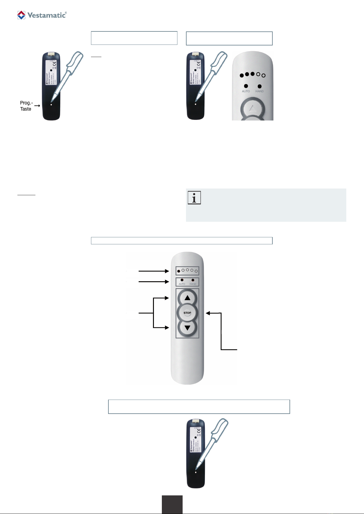
Overview operating elements
The VRS WISO Crystal Control should be wall-mounted, and a magnet
should be used to configure the sensor of the control.
Instead of pressing a mechanical button, you hold the magnet close to the
housing (correct location is marked by the words PROG POINT) as shown
below.
Through the transparent housing you can see several LEDs. Green LEDs
show the current sun intensity, and red LEDs show the current wind speed.
1. Magnet
2. PROG POINT
3. Wind sensor
4. Lux sensor
5. Single red LED (lit during programming mode)
6. Single yellow LED (lit when magnet is hold close to PROG POINT, etc.)
7. Wind: 8 red LEDs show wind speed
8. Sun: 8 green LEDs show sun intensity
LED feedback
The control contains different visible LEDs.
8 green LEDs show the sun intensity and threshold.
8 red LEDs show the wind speed and threshold.
1 red LED shows if programming mode is activated.
1 yellow LED shows if rain/frost function is activated.
LEDs are automatically turned off after 60 minutes when it’s dark (= 0 kLux)
.
Pressing the PROG POINT quickly will turn on the LED feedback for 5 min-
utes.
If wind/sun /rain function is activated during night, the LEDs are temporary
turned on as long as any function is active.
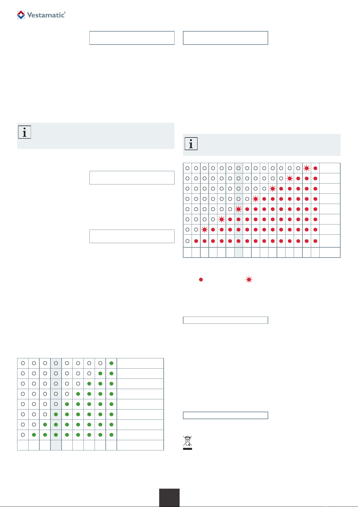
During normal operation, the 8 sun and 8 wind LEDs are turned on from
the bottom to the top, to indicate the current sun and wind value.
Red/green LED row:
One LED on each row is flashing. This slow flashing indicates the thresh-
old values. This makes it easy to see if the current wind or sun is close to
exceeding the threshold value.
If the current value is above the threshold value, the LED will flash fastly.
If the current value is above the threshold value for a longer time and acti-
vates the function, it’s indicated with a rapid flashing “threshold LED”. The
LED will flash rapidly until current value is low, OFF-delay is exceeded and
function is inactive again.
If the complete row of all red LEDs are flashing quickly, this means that the
wind sensor hasn’t been working for 48 hours. Wind function is active as
long as wind sensor is marked as “broken”, the sun protection will be retracted.
Yellow LED:
The single yellow LED is normally turned off.
Yellow LED is also light when PROG POINT is pressed. This is a visual
feedback that magnet is held in correct position.
The single yellow LED will flash fast when rain function is activated
as secu-
rity function and all motors are locked in upper position.
Single Red LED:
The single red LED is normally turned off.
The single red LED is turned on if you enter the “Programming mode”.
Wind sensor (wind alarm)
If the current value is above the threshold value, the red LED will flash
fastly. All sunshades are retracted and locked in upper position.
If you try to control the motor via remote, the motor will move shortly down
and up.
Wind sensor (48 hour protection)
If wind sensor doesn’t detect any wind pulses for 48 hours, wind sensor is
marked as “broken”, and wind function is activated.
All sunshades are retracted and locked to the upper position. If you try to
control the motor via remote, the motor will move shortly down and up.
This state is also indicated by flashing all red LEDs as long as sensor is
marked as “broken”.
By full turn of the propeller, the sensor is marked as fixed again, and
motors are unlocked again. Other functions, such as sun function or
manual UP/DOWN commands, can now be activated again.
Additional accessories
The control can be connected to a rain sensor.
Rain sensor RD +1 °C (32 °F), Article-no.: 01083560
The rain sensor will retract the sunshades and protect against rain and frost.

Subject to modifications.© Vestamatic GmbH
Art.-Nr.: 85700621 H1 • Vestamatic GmbH • Dohrweg 27 • D-41066 Mönchengladbach • www.vestamatic.com
VRS WISO Crystal Control
3/4
G
Function and programming VRS WISO Transmitter 5
Programming a VRS WISO Transmitter 5
for initial operation respectively after RESET
Now press the prog.-button (Fig. A) on the backside
of the transmitter, followed by the STOP button.
Successful programming:
The motor will confirm this with two short movements
in both directions.
Fig. A
Select the required switching channel on your transmitter. Change chan-
nel as described above by pressing the STOP button.
Switch OFF the power supply of the motor for minimum 3 seconds.
Switch ON the power supply again, the motor is now in programming
mode for 30 seconds.
Ergonomics to “add/pair”
control + motor
With VRS WISO Transmitter 5:
You need a
VRS WISO Transmitter 5
to
add the control to a motor. This trans-
mitter must be known/authorized by the
system.
With this
transmitter
you put the motor
into “learn” mode. When motor is in
“learn” mode, hold magnet close to
PROG POINT at the sensor, and it will
control your motor.
Please proceed in the following way:
– Press and release prog.-button once on the backside of
VRS WISO
Transmitter 5
(LED 1 blink).
– Press STOP button, and motor will move UP/DOWN and enter “learn”
mode.
– Hold magnet close to PROG POINT at the sensor. If sensor is con-
nected to the motor, the motor will confirm this with a short movement
in both directions.
Control is now paired with the motor and will control the motor.
Without VRS WISO Transmitter 5:
If a VRS WISO Transmitter 5 is not available, the motor can be turned
OFF/ON to enter
“learn”
mode for 60 seconds. This will also allow the user to
add the sensor to the motor by holding magnet close to PROG POINT at the
sensor. The motor will confirm this with a short movement in both directions.
Ergonomics to “remove/unpair”
control + motor
You need a
VRS WISO Trans-
mitter 5
to remove the control
from a motor. This transmitter
must be known/authorized by
the system.
With this transmitter you put
the motor into “forget
”
mode.
When motor
is in
“forget”
mode, hold magnet close to
PROG POINT
at the sensor,
and it will be removed from
your system.
Please proceed in the following way:
– Press prog.-button on the backside of
VRS WISO Transmitter 5
until
LED 1, 2, 3 is lit.
– Press STOP button.
– Hold magnet close to PROG POINT at the sensor (within 10 seconds).
If sensor is removed from the motor, the motor will confirm this with a
short movement in both directions.
Control is now unpaired from the motor, and will not control the motor any-
more.
Note:
If you switch off the power of the VRS WISO Crystal Control, the
motor will be locked by the security time-out after some minutes.
Therefore it’s important to unpair the devices if you want to re-
move the sensor permanently.
A. LED indication of selected channel of the
transmitter. In total there are five channels on
the transmitter.
B. VRS WISO Transmitter 5:
Used to select and display manual or
automatic mode.
C. Manual control buttons.
Channel 1– 5 = Motor / Shade
Button ON/UP = Q
Button STOP
Button OFF/DOWN = q
To change manual/automatic mode:
Press and hold STOP button for 7s, then use
ON/UP Q or OFF/DOWN q button to select
manual or automatic mode. Confirm mode by
pressing STOP button.
Manual mode:
Motor is controlled only by
wind functionality.
Automatic mode:
Motor is controlled by
sun and wind functionality.
To change channel:
Press and hold STOP button for 3–6s (LED
start to blink), then use the ON/UP Q or OFF/
DOWN q button to select wanted channel and
confirm by pressing STOP button.
A.
B.
C.

Subject to modifications.© Vestamatic GmbH
Art.-Nr.: 85700621 H1 • Vestamatic GmbH • Dohrweg 27 • D-41066 Mönchengladbach • www.vestamatic.com
VRS WISO Crystal Control
4/4
G
Programming mode
The sensor has a magnetic switch described as PROG POINT to enter
the programming mode. After entering the programming mode, you will be
able to change threshold values.
Settings sun Sun threshold (green LEDs)
Settings wind Wind threshold (red LEDs)
IMPORTANT: You can only edit and change one threshold at a time.
If you edit both sun and wind threshold and select “save &
apply”, only wind threshold will be saved. Sun threshold will
revert to the old value. The main reason is to avoid chang-
ing some unwanted threshold.
Note:
Wind function is still detecting the wind speed when you are in pro-
gramming mode. This means that you might “accidently” activate
the wind function if you manually turn the wind sensor too quick.
Programming mode:
LED description
When you enter the programming mode, it’s possible to modify sun and
wind threshold values. Make sure wind threshold is set to a value suitable
to your sun shading installation.
Programming mode:
Sun threshold
The sun threshold can be set to a value between 5 kLux and 40 kLux.
(Default is 15 kLux). Sun threshold is adjusted within the first programming
mode. One whole turn (360°) increase 5 kLux. To change sun threshold
from 20 kLux to 30 kLux you should turn wind sensor 2 turns totally.
How to enter programming mode to change sun settings:
1. Hold magnet close to PROG POINT for 3 seconds.
The green and red LEDs will be lit up.
2. The single red LED will be lit as long as you are in programming mode.
3. Turn wind sensor to change sun threshold. The sun threshold will be
indicated by the green LED row.
4. Hold magnet close to PROG POINT for 3 seconds to “save & apply”
the new sensor mode. If you skip this step, it will revert to the old settings.
After 5 minutes the sensors exit the programming mode automatically.
Note: If no green LEDs are lit, the sun function is switched off.
Top LED
Lowest LED
OFF
5 10 15 20 25 30 35 40 kLux
Default SUN threshold is 15 kLux is indicated by LED 1, 2, 3 lit.
Programming mode:
Wind threshold
(Default is 8 m/s). Wind threshold is adjusted with the second programming
mode. One half turn (180°) increase 1 m/s, and one whole turn (360°) in-
crease 2 m/s. To change wind threshold from 5 m/s to 9 m/s you should
turn wind sensor 2 turns totally.
How to enter programming mode to change wind settings:
1. Hold magnet close to PROG POINT for 3 seconds.
The green and red LEDs will be lit up.
2. The single red LED will be lit as long as you are in programming mode.
3. Hold magnet close to PROG POINT again.
4. Turn wind sensor to change wind threshold. The wind threshold will be
indicated by the red LED row.
Note:
The threshold accuracy is higher than the LEDs can present.
The “middle” values are displayed by a flashing LED.
Top LED
Lowest
LED
03456789 10 11 12 13 14 15 16 17 m/s
Default WIND threshold is 8 m/s is indicated by LED 1, 2, 3 lit,
LED 4 blinking.
Note: indicates lit LED, indicates flashing LED.
Factory reset
If you want to reset all settings into factory default settings, follow this
instruction:
1. Power off the wind / lux sensor.
2. Hold PROG POINT (magnet close to housing) for 5 seconds when the
control is powered on.
3. Note: All 8 green and 8 red LEDs will be lit when sensor is powered on.
4. After 2 seconds, all red and green LEDs are alternatively blinking and all
settings are reset to factory default settings.
Disposal of waste
The disposal of electrical equipment and batteries in household waste
is strictly forbidden.
The symbol (dustbin crossed out, in line with WEEE Appendix IV) in-
dicates separate collection of electrical and electronic products in EU
countries. Do not dispose of the device or battery in your household
waste. Ask your town or local council about the return and collection
systems available in your area to dispose of this product.
Other Vestamatic Weather Station manuals