VESTEL MB120 DS User manual

MB120 DS
SERVICE MANUAL

1
Table of Contents
1. INTRODUCTION ................................................................................................................................................... 2
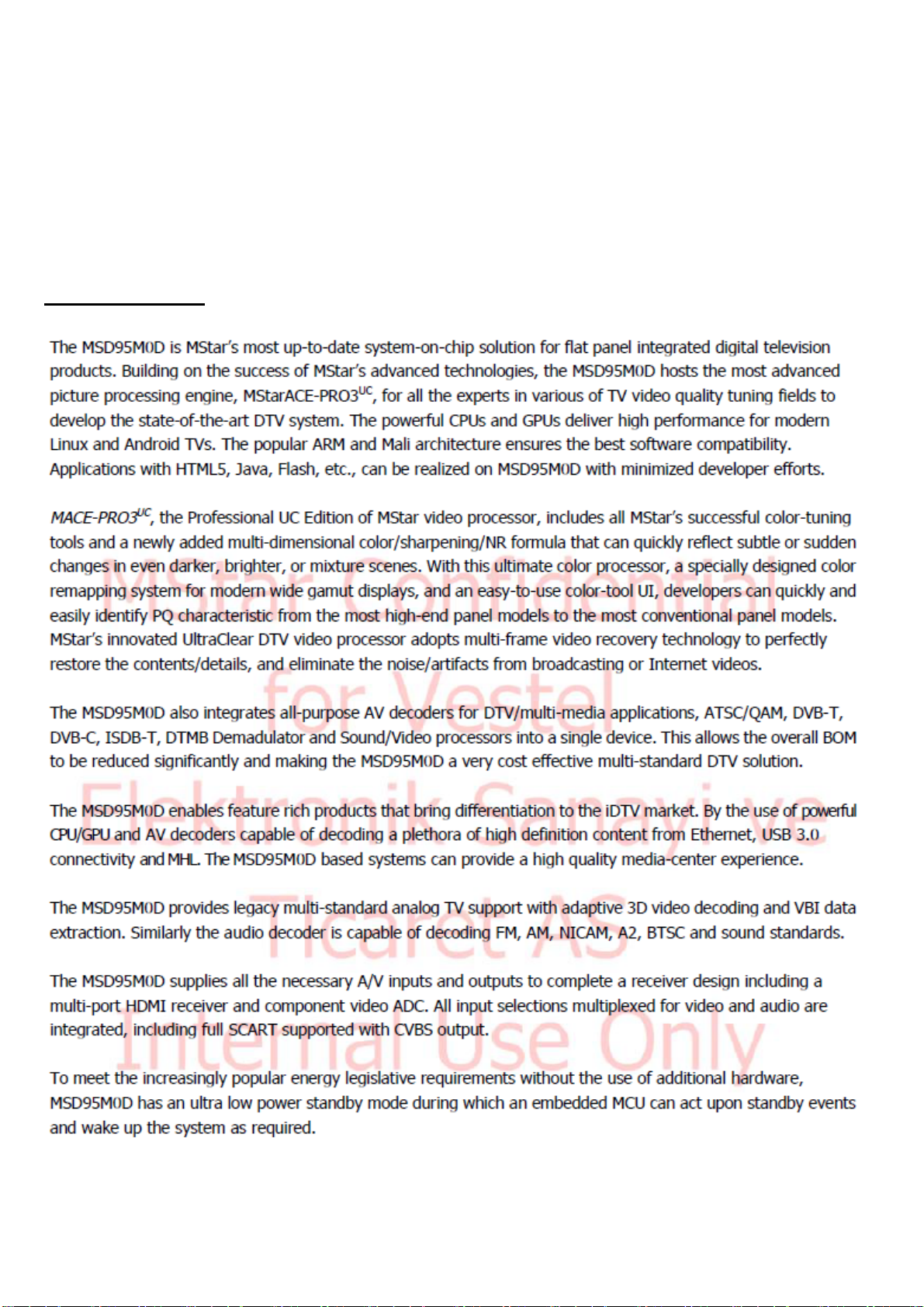
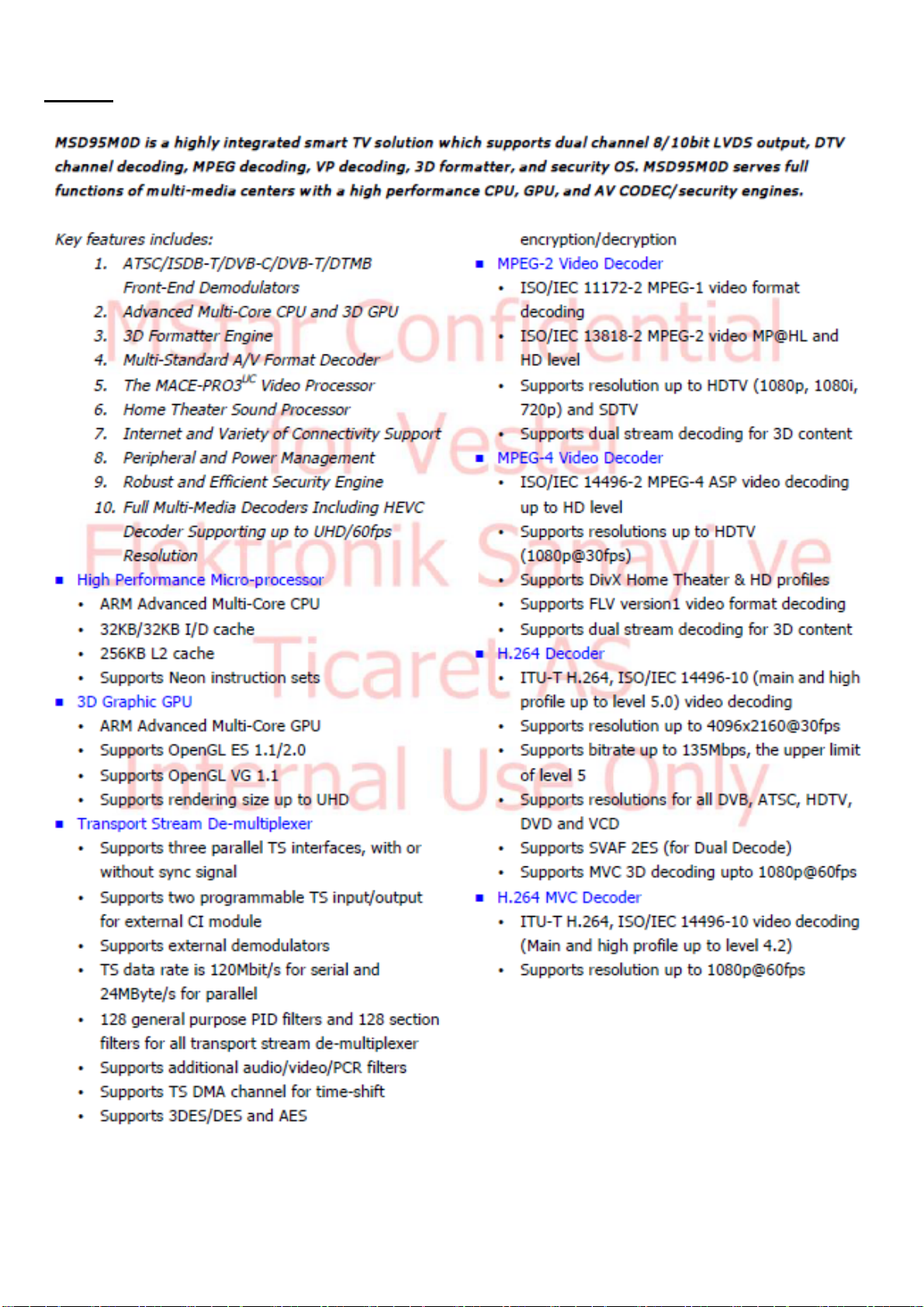
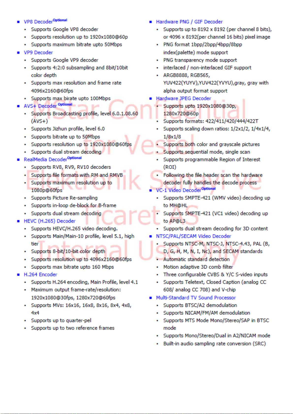
2. MICROCONTROLLER (MSTAR MSD95M0D)..................................................................................................... 3
3. VIDEO BACK-END PROCESSOR (MSTAR) .......................................................................................................10
MST7410FE.......................................................................................................................................................... 10
4. AUDIO AMPLIFIER STAGES ..............................................................................................................................13
A. MAIN AMPLIFIER (U8) (10W/12W options) ...................................................................................................13
B. HEADPHONE AMPLIFIER (U59)....................................................................................................................15
C. SUBWOOFER PREAMPLIFIER (U30).............................................................................................................16
5. POWER STAGE.....................................................................................................................................................17
A. TPS54528..........................................................................................................................................................18
B. TPS54628..........................................................................................................................................................20
C. TPS54821..........................................................................................................................................................22
D. TPS563200 ........................................................................................................................................................24
E. FDS4685............................................................................................................................................................26
F. NTGS3446.........................................................................................................................................................27
G. APL5910............................................................................................................................................................28
H. APL2111H.........................................................................................................................................................30
6. 2Gb DDR3 SDRAM ...............................................................................................................................................32
Hynix H5TQ2G63GFR.......................................................................................................................................... 32
7. 4Gb DDR3L SDRAM.............................................................................................................................................33
Hynix H5TQ4G63GFR.......................................................................................................................................... 33
8. 32GBIT (4G X 8 BIT) NAND FLASH MEMORY..................................................................................................35
MT29F4G08ABAEAWP....................................................................................................................................... 35
9. 16M-BIT [16M x 1] CMOS SERIAL FLASH EEPROM.........................................................................................37
A. MX25L1606E SPI Flash ....................................................................................................................................37
B. M25Q32FV SPI Flash........................................................................................................................................39
10. STDP4320 (DP1.2 splıtter IC).................................................................................................................................41
11. ep9162s & EPF025r (HDMI 2.0a / HDCP2.2 Splitter IC)........................................................................................43
12. OPS - OPEN PLUGGABLE SPECIFICATION(OPtıonal) ......................................................................................46
13. TUNER (Optıonal)..................................................................................................................................................50
M88TS2022 SatellIte Tuner................................................................................................................................... 50
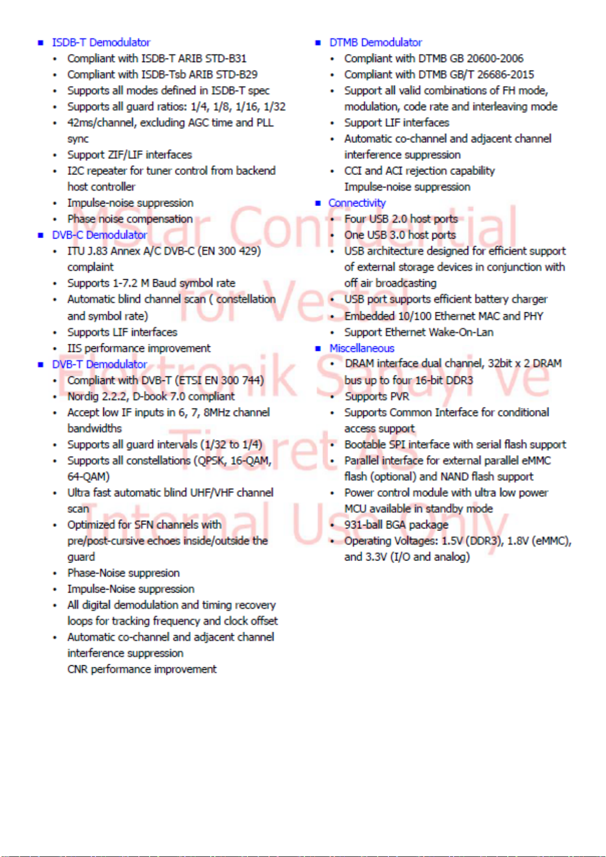
14. DEMODULATOR STAGE (Optıonal)....................................................................................................................52
15. LNB SUPPLY AND CONTROL IC (Optıonal).......................................................................................................55
TPS65233.............................................................................................................................................................. 55
16. bq32000 rtc Real-Time Clock (Optıonal).................................................................................................................56
17. SOFTWARE UPDATE...........................................................................................................................................57

2
A. Main SW update............................................................................................................................................. 57
B. Dısplayport fw update .................................................................................................................................... 57
C. HDMI SPLITTER FW UPDATE..................................................................................................................... 57
18. TROUBLESHOOTING..........................................................................................................................................58
A. No Backlıght Problem........................................................................................................................................58
B. Stayıng ın Stand-by Mode..................................................................................................................................61
C. IR Problem.........................................................................................................................................................62
D. Keypad Touchpad Problems...............................................................................................................................63
E. USB Problems....................................................................................................................................................64
F. No Sound Problem.............................................................................................................................................65
G. Standby On/Off Problem....................................................................................................................................65
H. No Sıgnal Problem .............................................................................................................................................65
I. Real tıme clock problem.....................................................................................................................................67
19. GENERAL BLOCK DIAGRAM ............................................................................................................................68
1. INTRODUCTION
17MB120DS main board is driven by MStar SOC. This IC is a single chip iDTV solution that supports
channel decoding, MPEG decoding, and media-center functionality enabled by a high performance AV
CODEC and CPU. This IC also supports 4K2K (UHD).
Key features includes:
•Combo Front-End Demodulator
•A multi standart A/V format decoder
•The MACEpro video processor
•Home theatre sound processor
•Internet and Variety of Connectivity Support
•Dual-stream decoder for 3D contents
•Multi-purpose CPU for OS and multimedia
•Peripheral and power management
Supported peripherals are:
•HDCP 2.2 / HDMI1.4 (FHD) input (1 HDMI default, 1 HDMI opt. with DVI, 1 HDMI opt. with OPS)
•HDCP 2.2 / HDMI2.0 (UHD) input (1 HDMI default, 1 HDMI opt. with DVI, 1 HDMI opt. with OPS)
•1 Displayport1.2a input / 1 DP 1.2a output
•1 PC (VGA) input
•1 YPbPr / Back S-Video
•Line In/ Line out
•1 Optic S/PDIF output
•1 USB 3.0, 1 USB 2.0 port
•1 USB2.0 for touchscreen (optional)
•1 OPS interface (optional)
•1 Extender IR

3
•1 Dsub9 RS232
•1 RJ45 10/100 Support Ethernet
•1 RJ12 (for service only)
•Tuner ATV/DVB-T/T2/C (optional)
•4K2K@ 50/100Hz Vby1, FHD@ 50/100Hz LVDS interface
2. MICROCONTROLLER (MSTAR MSD95M0D)
General Description

4
Features

5

6

7

8

9
Table 1: Recommended operating conditions.
Table 2: Absolute Maximum Ratings

10
3. VIDEO BACK-END PROCESSOR (MSTAR)
MST7410FE
General Description
Table 3: Recommended operating conditions

11
Features

12
Block Diagram
Figure 1: Block diagram

13
4. AUDIO AMPLIFIER STAGES
A.MAIN AMPLIFIER (U8) (10W/12W OPTİONS)
Description
AD82587D is a digital audio amplifier capable of driving a pair of 8 ohm, 20W or a single 4 ohm, 40W
speaker, both which operate with play music at a 24V supply without external heat-sink or fan requirement.
Using I2C digital control interface, the user can control AD82587D’s input format selection, DRC (dynamic
range control), mute and volume control functions. AD82587D has many built-in protection circuits to
safeguard AD82587D from connection errors.
Features
•16/18/20/24-bit input with I2S, Left-alignment and Right-alignment data format
•PSNR & DR(A-weighting) Loudspeaker: 97dB (PSNR), 105dB (DR) @ 24V
•Multiple sampling frequencies (Fs)
−32kHz / 44.1kHz / 48kHz and
−64kHz / 88.2kHz / 96kHz and
−128kHz/176.4kHz/192kHz
•System clock = 64x, 128x, 256x, 384x, 512x, 768x,1024x Fs
−256x~1024x Fs for 32kHz / 44.1kHz / 48kHz
−128x~512x Fs for 64kHz / 88.2kHz / 96kHz
−64x~256x Fs for 128kHz /176.4kHz/192kHz
•Supply voltage
−3.3V for digital circuit
−10V~26V for loudspeaker driver
•Loudspeaker output power for Stereo@ 24V
−10W x 2ch into 8_ @ 0.16% THD+N
−15W x 2ch into 8_ @ 0.18% THD+N
−20W x 2ch into 8_ @ 0.24% THD+N
•Loudspeaker output power for Mono@ 24V
−20W x 1ch into 4_ @ 0.17% THD+N
−30W x 1ch into 4_ @ 0.2% THD+N
−40W x 1ch into 4_ @ 0.24% THD+N
•Sounds processing including:
−Volume control (+24dB~-103dB, 0.125dB/step)
−Dynamic range control
−Power clipping
−Channel mixing
−User programmed noise gate with hysteresis window
−DC-blocking high-pass filter
•Anti-pop design
•Short circuit and over-temperature protection
•I2C control interface with selectable device address
•Internal PLL
•LV Under-voltage shutdown and HV Under-voltage
•detection
•Power saving mode
•Dynamic temperature control

14
Figure 2: Pin description
Figure 3: Functional Block Diagram
Table 4: Absolute Maximum Ratings

15
Table 5: Recommended Operating Conditions
B.HEADPHONE AMPLIFIER (U59)
Description
The AD22657B is a 2-Vrms cap-less stereo line driver. The device is ideal for single supply electronics.
Cap-less design can eliminate output dc-blocking capacitors for better low frequency response and save cost.
The AD22657B is capable of delivering 2-Vrms output into a 10k ohm load with 3.3V supply. The gain
settings can be set by users from 1V/V to 10V/V externally. The AD22657B has under voltage protection to
prevent POP noise. Build-in shutdown control and de-pop control sequence also help AD22657B to be a pop-
less device.
The AD22657B is available in a 10-pin MSOP package.
Features
•Operation Voltage: 3V to 3.6V
•Cap-less Output
−Eliminates Output Capacitors
−Improves Low Frequency Response
−Reduces POP/Clicks
•Low Noise and THD
−Typical SNR 107dB
−Typical Vn 7uVrms
−Typical THD+N < 0.02%
•Maximum Output Voltage Swing into 2.5k Load
−2Vrms at 3.3V Supply Voltage
•Single-ended Input
•External Gain Setting from 1V/V to 10V/V
•Fast Start-up Time: 0.5ms
•Integrated De-Pop Control
•External Under Voltage Protection
•Thermal Protection
•Less External Components Required
•+/-8kV IEC ESD Protection at line outputs

16
Figure 4: Pin description
Table 6: Pin functions
Table 7: Recommended operating conditions
C.SUBWOOFER PREAMPLIFIER (U30)
AD22657B is used for subwoofer out, as well.

17
5. POWER STAGE
Figure 5: Power socket and options.
Power socket is used for taking voltages which are 12V, 5V and VDD_Audio. These voltages are produced
in power board. Also socket is used for giving dimming, backlight and standby signals with power board. It is
shown at figure 4.1.

18
Figure 6: General illustration of voltage stages on main board.
VDD_Audio goes directly to the audio side, through power socket other incoming voltages from power card
are converted several voltages, shown in figure 4.2.
List of the components are:
•TPS54528
•TPS54628
•TPS54821
•TPS56320
•FDS4685
•NTGS3446
•APL5910
•AP2111H
A.TPS54528
General Description
The TPS54528 is an adaptive on-time D-CAP2 mode synchronous buck converter.The TPS54528 enables
system designers to complete the suite of various end-equipment power bus regulators with a cost effective, low
component count, low standby current solution. The main control loop for the TPS54528 uses the D-CAP2
mode control that provides a fast transient response with no external compensation components. The adaptive
on-time control supports seamless transition between PWM mode at higher load conditions and Eco-mode
operation at light loads. Eco-mode allows the TSP54528 to maintain high efficiency during lighter load
conditions. The TPS54528 also has a proprietary circuit that enables the device to adopt to both low equivalent
series resistance (ESR)output capacitors, such as POSCAP or SP-CAP, and ultra-low ESR ceramic capacitors.

19
The device operates from 4.5-V to 18-V VIN input. The output voltage can be programmed between 0.76 V
and 6 V. The device also features an adjustable soft start time. The TPS54528 is available in the 8-pin DDA
package, and designed to operate from -40 C to 85 C.
Features
•D-CAP2 Mode Enables Fast Transient Response
•Low Output ripple and Allows Ceramic Output Capacitor
•Wide VIN Input Voltage Range: 4.5 V to 18 V
•Output Voltage Range: 0.76 V to 6 V
•Highly Efficient Integrated FETs Optimized for Lower Duty Cycle Applications- 65 mOhm (High Side)
and 36 mOhm (Low Side)
•High Efficiency, less than 10 mikroAmper at shutdown
•High Initial Bandgap Reference Accuracy
•Adjustable Soft Start
•Pre-Biased Soft Start
•650-kHz Switching Frequency (fSW)
•Cycle By Cycle Over Current Limit
•Auto-Skip Eco-mode for High Efficiency at Light Load
Applications
•Wide Range of Applications for Low Voltage System
•Digital TV Power Supply
•High Definition Blu-ray Disc Players
•Networking Home Terminal
•Digital Set Top Box(STB)
Table 8: Recommended operating conditions
Figure 7: Pin Description
Table of contents
Other VESTEL Motherboard manuals