Vicpas Houston Street H30 User manual

M H O M
Model H30 Version 1.0
Houston Street Technologies
August 1, 2007

H30 Operation Manual Houston Street Technologies
2

H30 Operation Manual Houston Street Technologies
3
H S T
135 West Davenport Street
Rhinelander WI 54501
Phone: 866.441.7997
Fax: 866.278.0036
info@houstonst.com
www.houstonst.com

H30 Operation Manual Houston Street Technologies
4
Table of Contents
INTRODUCTION ...................................................................................................................5
SPECIFICATIONS...................................................................................................................5
USER INTERFACE ..................................................................................................................6
INSTALLATION ......................................................................................................................7
QUICK START GUIDE...........................................................................................................9
MANUAL OPERATION MODES.......................................................................................10
AUTO OPERATION MODE................................................................................................11
ENGINE STALL PROTECTION (ESP) ..............................................................................12
DIGITAL INPUTS .................................................................................................................14
DIGITAL OUTPUTS.............................................................................................................15
SECURITY ..............................................................................................................................15
CONTRAST ADJUSTMENT...............................................................................................16
TROUBLESHOOTING.........................................................................................................16
CONTACT ..............................................................................................................................16

H30 Operation Manual Houston Street Technologies
5
1. Introduction
Houston Street Technologies’ Model H30 diesel engine controller was designed to provide simple, accurate and
consistent engine control for a variety of diesel power applications. When used with an ECU controlled engine
the H30 utilizes SAE J1939 CAN bus protocol to communicate desired engine control characteristics as well as
display all relevant engine operating parameters and fault codes, both stored and active.
In addition to its core functionality of MANUAL RAMP, MANUAL STEP, AUTO and ENGINE STALL
PROTECTION (ESP), the H30 can also be tailored to any customer’s request for a wide range of unique industrial
applications.
2. Specications
Environmental Protection: IP65 (pending)
Operating Voltage: 8-32VDC
Operating Temperature: -20° to +70°C (-4 to +158°F) [without LCD heater]
Operating Temperature: -30° to +70°C (-22 to +158°F) [with LCD heater]
Storage Temperature: -30° to +80°C (-22 to +176°F)
Display: FSTN, LED Backlit, 240 X 320 Pixels, 3.9” Diagonal, Full Monochrome Graphics
Housing Connectors: (1) Deutsch DT04-12PA, (1) Deutsch DT04-12PB, (1) Deutsch DT04-12PC
Mating Connectors: (1) Deutsch DT06-12SA, (1) Deutsch DT06-12SB, (1) Deutsch DT06-12SC
Digital Outputs: (3) Dedicated SPST, 10 Amp Relays
(4) Programmable SPST, 3 Amp Relays
Digital Inputs: (8) Common Ground, Digital Inputs
Analog Inputs: (4) Programmable 4-20 mA, 0-5 VDC or Resistive Inputs
Standard Communications: J1939 CAN bus, RS485
Optional Communications: Cellular, RF (FUTURE DEVELOPMENT)

H30 Operation Manual Houston Street Technologies
6
3. User Interface
e H30’s monochrome graphical LCD display is used as a visual interface for the operator. e H30’s primary
screen is the Operation Screen (shown below), which displays user-dened operating parameters on three analog
gauge faces as well as scrolling text for a total of six parameters in addition to any active fault codes being broadcast
by the engine ECU.
e power button is used to regulate power to the H30 and stop the engine from running. e engine can only be
started when the H30 is powered and displaying the Operation Screen. e engine can be shutdown by pressing
the power button when the engine is running.
CAUTION: Engine manufacturer recommendations should always be followed when shutting down the
engine.
On the face of the controller an amber LED is used as an active warning fault indicator, while a red LED is used
as a derate or shutdown indicator.
The six tactile push buttons on the face of the H30 have the following general functions:
1. UP: Increase RPM, Scroll Menu Lists
2. DOWN: Decrease RPM, Scroll Menu Lists
3. ENTER: Select Highlighted Menu Item,
Press/Release to Access Main Menu, Hold to
Crank Engine
4. RIGHT: Increase Parameter Value
5. LEFT: Decrease Parameter Value
6. POWER BUTTON
RED LED
AMBER LED

H30 Operation Manual Houston Street Technologies
7
4. Installation
e cutout pattern required for surface mounting the H30 is shown below:

H30 Operation Manual Houston Street Technologies
8
CAUTION: Power supply at pin 2 of Connector A (ECU Power) should be protected with a 10 Amp fuse or
circuit breaker.
Connector A is required for electronic engines.
Connectors A and B are required for mechanical engines.
Connector C is required for extended features only.
CONNECTOR/ PIN NO. DESCRIPTION
A1 GROUND
A2 FUSED ECU POWER SUPPLY, 10 AMP
A3 ALTERNATOR EXCITE
A4 START RELAY
A5 ECU POWER/FUEL SOLENOID HOLD
A6 CAN SHIELD
A7 CAN LO
A8 CAN HI
A9 RS485 (+)
A10 RS485 (-)
A11 DIGITAL OUTPUT POWER SUPPLY
A12 H30 POWER SUPPLY
B1 DIGITAL INPUT #1
B2 DIGITAL INPUT #2
B3 DIGITAL INPUT #3
B4 DIGITAL INPUT #4
B5 ANALOG INPUT #1 (+)
B6 ANALOG INPUT #1 (-)
B7 ANALOG INPUT #2 (+)
B8 ANALOG INPUT #2 (-)
B9 MAGNETIC PICKUP INPUT (+)
B10 MAGNETIC PICKUP INPUT (-)
B11 DIGITAL OUTPUT #1
B12 DIGITAL OUTPUT #2
C1 DIGITAL INPUT #5
C2 DIGITAL INPUT #6
C3 DIGITAL INPUT #7
C4 DIGITAL INPUT #8
C5 DIGITAL OUTPUT #3
C6 DIGITAL OUTPUT #4
C7 ANALOG INPUT #3 (+)
C8 ANALOG INPUT #3 (-)
C9 ANALOG INPUT #4 (+)
C10 ANALOG INPUT #4 (-)
C11 RS232 Tx
C12 RS232 Rx

H30 Operation Manual Houston Street Technologies
9
5. Quick Start Guidelines
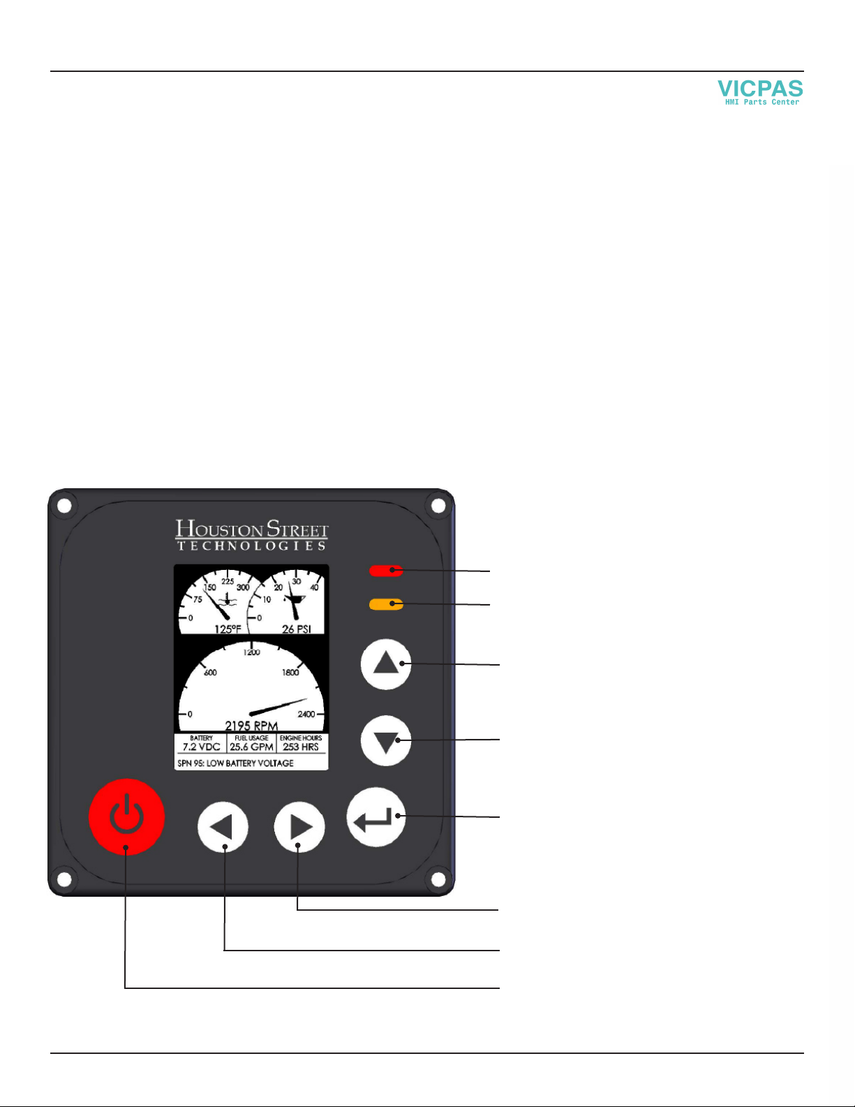
POWER UP
When the power button is pressed the H30 will display a splash screen that will show a company logo and
controller information. Aer the splash screen has timed out and if START UP SECURITY is not enabled, the
Operation Screen will be displayed. If START UP SECURITY is enabled, a 4-digit PIN is required to access the
functionality of the controller.
CONTROLLER SETUP
e Main Menu can be accessed by pressing and releasing the ENTER button while at the Operation Screen. All
other sub menus can be accessed from the Main Menu.
See detailed controller setup instructions in the following sections of this manual.
ENGINE START UP
While at the Operation Screen the engine can be started by pressing and holding the ENTER button. e engine
can only be started from the Operation Screen.
NOTE: e H30 protects the engine starter from damage by limiting the time that the operator can crank the
engine to 15 seconds with a 30 second rest between cranks.
When used with an electronically controlled engine, the engine ECU may be programmed to use a cold start
aid (block heater, air intake heater, glow plugs, etc.), a notice will be displayed informing the user that an engine
preheat is taking place and to wait for the preheat operation to complete before attempting to start the engine.
If the ECU COMMUNICATION ERROR is ashing on the H30 screen, the engine will not start.
ENGINE CONTROL
While the engine is running and the H30 is displaying the Operation Screen, the UP and DOWN buttons will
increase and decrease the engine speed, respectively. e manner in which the speed increases or decreases
depends on the current Operation Mode: MANUAL RAMP, MANUAL STEP or AUTO RAMP (MANUAL
RAMP is the default Operating Mode).
ENGINE SHUTDOWN
When the power button is pressed while the engine is running, the engine will shutdown immediately.
CAUTION: Always follow engine manufacturer recommendations for controlled engine shutdowns prior
to pressing the power button.
If operating conditions cause the engine ECU to derate or shutdown the engine, the controller’s red LED will
ash and the engine will derate or shutdown based on the engine ECU’s programming.

H30 Operation Manual Houston Street Technologies
10
6. Manual Operation Modes
MANUAL RAMP
When in MANUAL RAMP mode the engine will operate within a range of congurable low and high RPM
values, increasing and decreasing speed in one of two manners: 5 second linearly or exponentially.
When using 5 second linear ramp rate the engine speed will increase from the low RPM setting to the high RPM
setting in a 5 second interval when the UP button is held. Engine speed will decrease in the same manner when
the DOWN button is held.
When using exponential ramp rate the engine speed will rapidly increase from the low RPM setting to the high
RPM setting when the UP button is held. Engine speed will decrease in the same manner when the DOWN
button is held.
When operating the engine using either ramp rate, each individual press of the UP or DOWN button will
increase or decrease the engine speed by approximately 16 RPM.
To access the MANUAL RAMP SETUP screen:
1) Press ENTER while at the Operation Screen to access the Main Menu.
2) Use U/D buttons to highlight OPERATING MODE and press ENTER.
3) Use L/R buttons to change the Operating Mode to MANUAL RAMP.
4) Use U/D buttons to highlight MANUAL RAMP SETUP and press ENTER.
MANUAL STEP
When in MANUAL STEP mode the engine will operate within a range of low and high RPM values, increasing
and decreasing speed in set increments. A maximum of (10) steps can be used to quickly (or slowly) increase or
decrease engine speed with each press of the UP or DOWN button.
To access the MANUAL STEP SETUP screen:
1) Press ENTER while at the Operation Screen to access the Main Menu.
2) Use U/D buttons to highlight OPERATING MODE and press ENTER.
3) Use L/R buttons to change the Operating Mode to MANUAL STEP.
4) Use U/D buttons to highlight MANUAL STEP SETUP and press ENTER.
RPM
IDLE
MANUAL STEP
STEP 1 STEP 2 STEP 3 STEP 4

H30 Operation Manual Houston Street Technologies
11
7. Auto Operation Modes
When in AUTO RAMP mode the engine will start and stop based o of digital inputs or pressing the U/D
buttons. Startup and shutdown proles of TIME vs. RPM are congurable, allowing for warm up and cool down
cycles to minimize stress on both the engine and engine-driven equipment.
To access the AUTO RAMP SETUP screen:
1) Press ENTER while at the Operation Screen to access the Main Menu.
2) Use U/D buttons to highlight OPERATING MODE and press ENTER.
3) Use L/R buttons to change the Operating Mode to AUTO RAMP.
4) Use U/D buttons to highlight AUTO RAMP SETUP and press ENTER.
TIME (MINUTES)
STARTUP PROFILE
RPM
TIME (MINUTES)
SHUTDOWN PROFILE
RPM

H30 Operation Manual Houston Street Technologies
12
8. Engine Stall Protection (ESP)
When ENGINE STALL PROTECTION (ESP) is enabled, the H30 can be used to engage and disengage feed
rollers that may be overloading the engine, causing it to stall. One of the H30’s digital outputs can be congured
to engage the feed forward solenoid at a set RPM limit, while a second digital output can be used to reverse the
feed direction for a set amount of time (0.0 to 1.0 seconds) when a low RPM limit is reached. Reversing the
feed direction is optional, the H30 can be congured to simply stop feeding until the engine RPM’s increase to a
minimum threshold speed and then re-engage the feed forward solenoid.
ESP can be used with single- or dual-valve feed systems. See the following sections for details on each system
are below.
ESP - SINGLE VALVE
A single-valve feed system is comprised of a single 3-position valve that uses two solenoids to control hydraulic
oil ow, and ultimately the feed direction.
ENGAGE SPEED Minimum engine RPM at which the feed rollers will begin
feeding forward
DISENGAGE SPEED Engine RPM that the feed rollers will stop (and reverse if
enabled)
FEED FORWARD e digital output used to control the feed forward solenoid
FEED REVERSE e digital output used to control the feed reverse solenoid
REVERSE TIME Length of time the feed rollers will be reversed
VALVE DELAY Solenoid time delay between switching from forward to
reverse and vice versa (used to minimize stress on the
hydraulic system)
MANUAL FORWARD Digitalinputusedtomanuallyforwardthefeedrollerswhen
the engine is running
MANUAL REVERSE Digital input used to manually reverse the feed rollers when
the engine is running
SCREENSHOT - ESP SINGLE VALVE
ESP SETUP - SINGLE VALUE
ENGAGE SPEED: 2200 RPM
DISENGAGE SPEED: 1800 RPM
FEED FORWARD: D/O#
FEED REVERSE: D/O#
REVERSE TIME: 0.3 SECONDS
VALVE DELAY: .05 - 1.0 SECONDS
MANUAL FORWARD: D/I#
MANUAL REVERSE: D/I#
RETURN TO OPERATING MODE

H30 Operation Manual Houston Street Technologies
13
ESP - DUAL VALVE
A dual-valve feed system is comprised of dual 2-position valves that use one solenoid each to control hydraulic oil
ow, and ultimately the feed direction. e rst valve is an ON/OFF valve that controls hydraulic oil ow to the
feed system, while the second valve determines the direction of the feed rollers.
FEED CONTROL Option to control feed rollers, use OPEN TO RUN to allow
rollers to feed forward in the event of a relay or solenoid
failure, use CLOSE TO RUN to prevent wheel operation in
the event of a relay or solenoid failure
ENGAGE SPEED Minimum engine RPM at which the feed rollers will begin
feeding forward
DISENGAGE SPEED Engine RPM that the feed rollers will reverse
FEED FORWARD The digital output used to control the feed forward solenoid
FEED REVERSE The digital output used to control the feed reverse solenoid
REVERSE TIME Length of time the feed rollers will be reversed
MANUAL FORWARD Digital input used to manually forward the feed rollers when
the engine is running
MANUAL REVERSE Digital input used to manually reverse the feed rollers when
the engine is running
To enable/disable ESP:
1) Press ENTER while at the Operation Screen to access the Main Menu.
2) Use U/D buttons to highlight OPERATING MODE and press ENTER.
3) Use U/D buttons to highlight ESP.
4) Use L/R buttons to ENABLE or DISABLE.
(ESP settings can be congured by highlighting CONFIGURE ESP aer it has been enabled.)
When purchasing your controller you must specify the feed system that you will be using, controllers do not come
with both the single- and dual-valve system controls enabled.
NOTE: e above operating modes are included in the full feature H30. Your H30 may not include all of the
above operating modes.
SCREENSHOT - ESP DUAL VALVE
ESP SETUP - DUAL VALUE
FEED CONTROL: OPEN TO RUN
ENGAGE SPEED: 2200 RPM
DISENGAGE SPEED: 1800 RPM
FEED FORWARD: D/O#
FEED REVERSE: D/O#
REVERSE TIME: .03 SECONDS
MANUAL FORWARD: D/I#
MANUAL REVERSE: D/I#
RETURN TO OPERATING MODE

H30 Operation Manual Houston Street Technologies
14
9. Digital Inputs
Below is a list of settings for the (8) digital inputs currently available. Contact HST for additional input
settings.
DIGITAL INPUT SETTING CONTROLLER/ENGINE RESPONSE DISPLAYED MESSAGE
FLOAT SWITCH HIGH BEGINS AUTO STARTUP SEQUENCE "HIGH FLOAT SWITCH"
FLOAT SWITCH LOW BEGINS AUTO SHUTDOWN
SEQUENCE
"LOW FLOAT SWITCH"
HYDRAULIC OIL TEMP SHUTS ENGINE DOWN
IMMEDIATELY
"HYDRAULIC OIL TEMP HIGH"
LOW COOLANT SWITCH NONE, TEXT WARNING ONLY "LOW COOLANT LEVEL"
LOW FUEL LEVEL NONE, TEXT WARNING ONLY "LOW FUEL LEVEL"
LOW OIL LEVEL NONE, TEXT WARNING ONLY "LOW OIL LEVEL"
COOLANT TEMP DECREASES ENGINE SPEED TO IDLE "HIGH COOLANT TEMP"
OIL PRESSURE DECREASES ENGINE SPEED TO IDLE "LOW OIL PRESSURE"
OIL TEMP DECREASES ENGINE SPEED TO IDLE "HIGH OIL TEMP"
THROTTLE UP MIMICS CONTROLLER’S UP BUTTON "THROTTLE UP"
THROTTLE DOWN MIMICS CONTROLLER’S
DOWN BUTTON
"THROTTLE DOWN"
AIR FILTER RESTRICTION NONE, TEXT WARNING ONLY "AIR FILTER RESTRICTION"
FUEL FILTER RESTRICTION NONE, TEXT WARNING ONLY "FUEL FILTER RESTRICTION"
REMOTE START CRANKS ENGINE "REMOTE START"
EMERGENCY STOP SHUTS ENGINE DOWN
IMMEDIATELY
"EMERGENCY STOP"

H30 Operation Manual Houston Street Technologies
15
10. Digital Outputs
Below is a list of settings for the (4) digital outputs currently available. Contact HST for additional output
settings.
DIGITAL OUTPUT SETTING DESCRIPTION/USE
SWITCHED POWER POWER SUPPLIED WHEN CONTROLLER IS
TURNED ON
AUDIBLE ALARM USE TO DRIVE AN EXTERNAL WARNING/
SHUTDOWN ALARM
WARNING LIGHT USE TO DRIVE AN EXTERNAL WARNING
LIGHT, MIMICS AMBER LED
SHUTDOWN LIGHT USE TO DRIVE AN EXTERNAL SHUTDOWN
LIGHT, MIMICS RED LED
11. Security
STARTUP SECURITY
A 4-digit code can be used to prevent use of the controller by unauthorized operators. When STARTUP
SECURITY is enabled, the user will be prompted for a 4-digit code aer the controller is turned on. If entered
correctly the controller will continue on to the Operation Screen.
To enable/disable STARTUP SECURITY:
1) Press ENTER while at the Operation Screen to access the Main Menu.
2) Use U/D buttons to highlight UTILITIES and press ENTER.
3) Use U/D buttons to highlight STARTUP SECURITY and press ENTER.
4) To enable, enter a new 4-digit code.
5) To disable, enter the same 4-digit code used to enable STARTUP SECURITY.
CONFIGURATION SECURITY
A 4-digit code can be used to prevent unauthorized operators from changing controller settings. If
CONFIGURATION SECURITY is enabled settings cannot be changed without rst disabling
CONFIGURATION SECURITY. Note that CONFIGURATION SECURITY and STARTUP SECURITY are
two dierent security options and do not share their 4-digit codes with each other.
To enable/disable CONFIGURATION SECURITY:
1) Press ENTER while at the Operation Screen to access the Main Menu.
2) Use U/D buttons to highlight UTILITIES and press ENTER.
3) Use U/D buttons to highlight CONFIGURATION SECURITY and press ENTER.
4) To enable, enter a new 4-digit code.
5) To disable, enter the same 4-digit code used to enable CONFIGURATION SECURITY.

H30 Operation Manual Houston Street Technologies
16
12. Contrast Adjustment
e H30 has an automatic contrast feature that will adjust the LCD screen contrast based o of temperature. If
the contrast is too light or too dark the contrast can be manually adjusted by going to the MAIN MENU, then
UTILITIES, then ADJUST DISPLAY. Increasing the CONTRAST setting will darken the display, decreasing it
will lighten the display.
e automatic adjustment can be disabled if display contrast problems occur.
13. Troubleshooting
SYMPTOM SOLUTION
CONTROLLER WILL NOT POWER UP (NO LED’s
FLASHING AND NO LCD IMAGES)
CHECK THAT SYSTEM VOLTAGE (12/24 VDC) IS
BEING SUPPLIED TO PIN A12
“ECU COMMUNICATION ERROR” IS
DISPLAYED
CHECK THAT SYSTEM VOLTAGE (12/24 VDC) IS
BEING SUPPLIED TO PIN A2
DIGITAL OUTPUTS DO NOT WORK CHECK THAT SYSTEM VOLTAGE (12/24 VDC) IS
BEING SUPPLIED TO PIN A11
LCD DISPLAY IS TOO DARK OR TOO LIGHT GO TO: MAIN MENU…UTILITIES…ADJUST
DISPLAY, THEN INCREASE DISPLAY SETTING
TO DARKEN THE DISPLAY, DECREASE TO
LIGHTEN THE DISPLAY
CONTROLLER DOES NOT RESPOND TO
DIGITAL INPUTS
CHECK THAT THE INPUT BEING PROVIDED IS
SYSTEM GROUND
DISPLAY DOES NOT WORK CALL 866-441-7997
RED AND/OR AMBER LED’s DO NOT WORK CALL 866-441-7997
MEMBRANE SWITCH BUTTONS DO NOT
RESPOND
CALL 866-441-7997
ENGINE WILL NOT CRANK WHILE HOLDING
THE ENTER BUTTON
CALL 866-441-7997
14. Contact
If you have questions regarding the operation of the H30, suggestions for enhancements or the need for
custom programming, contact Houston Street Technologies.
Phone: 866.441.7997

H30 Operation Manual Houston Street Technologies
17
This manual suits for next models
1
Table of contents