WWW.VIDEOSYS.TV4
Two fundamentally different operating modes can be
selected between; Uni-directional camera control and Bi-
directional camera control. In Uni-directional mode camera
control is achieved with no return data path, this provides
the most robust camera control link. The downside of Uni-
directional control is that it limits the number of features on
a manufacturers RCP that can be used to those that we have
specically supported.
Bi-directional control requires a return data path, typically
provided by a COFDM video transmitter, it allows for the full
functionality of a manufacturers RCP. The downsides of
Bi-directional control are rstly that it needs two RF links,
both need to be good for successful control. Secondly a
synchronising process is needed to inform the RCP of the
cameras features (or potentially the other way around,
manufacturer dependant), this can lead to slower ‘wake
up’ times than with unidirectional control. Wake up time is
software/camera/panel and manufacturer dependant.
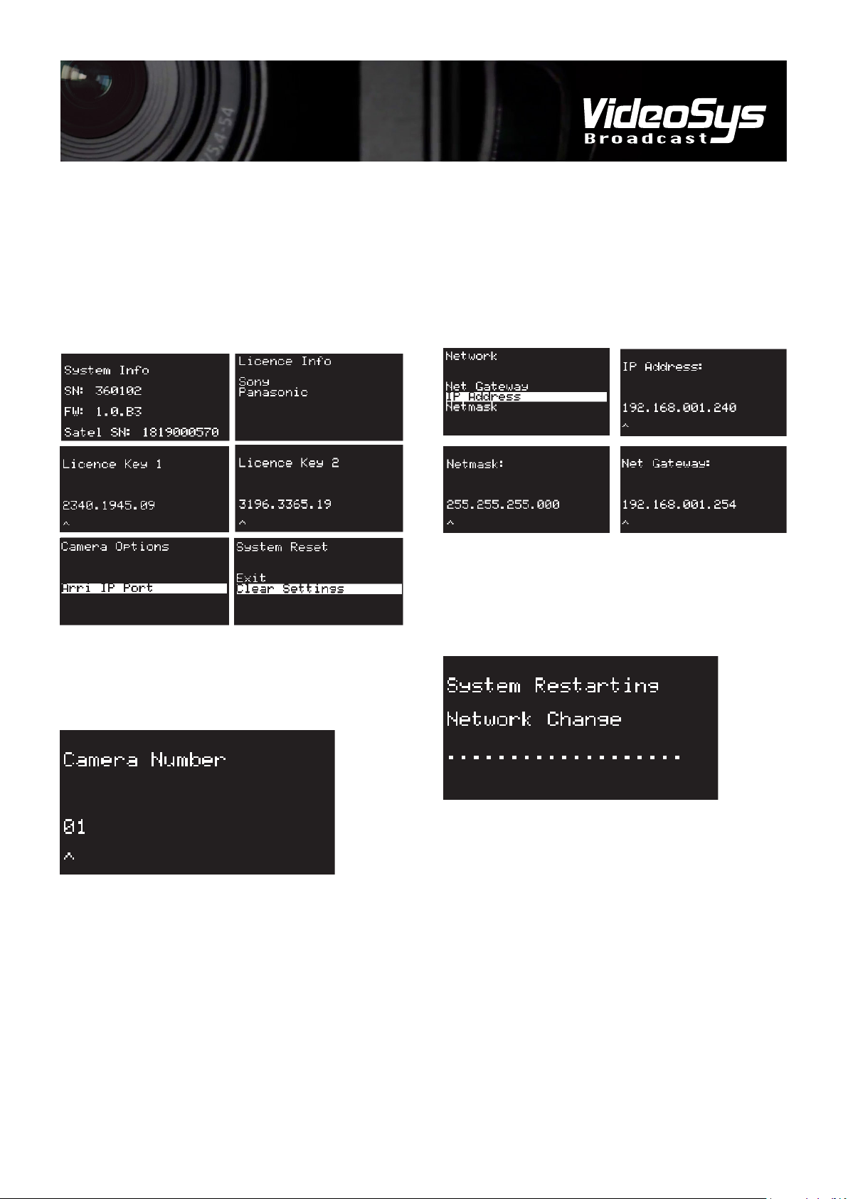
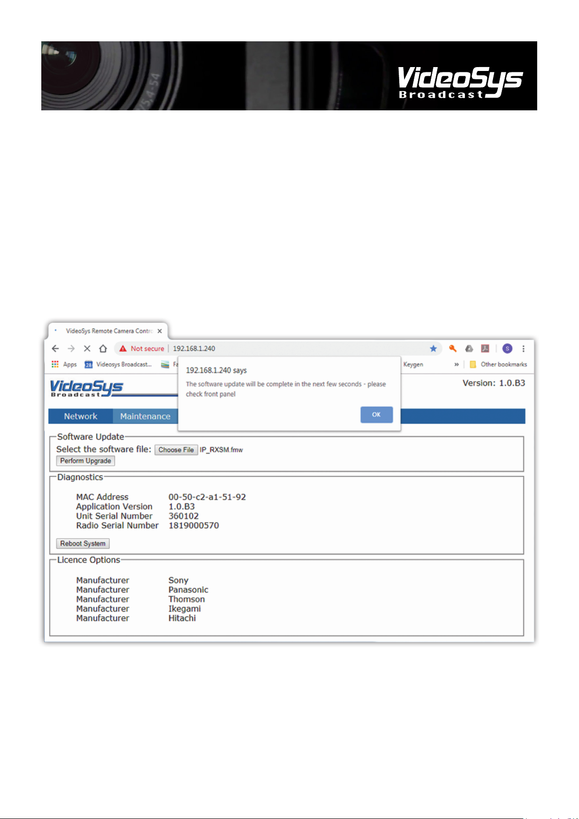
For more information on the functionality of the RX as part of
a camera control system, please refer to the IDU manual and
our range of specic set up guides.
The most basic Uni-directional set up is shown in Fig 1.
Where a single ODU is sending control data to be received by
a single RX.
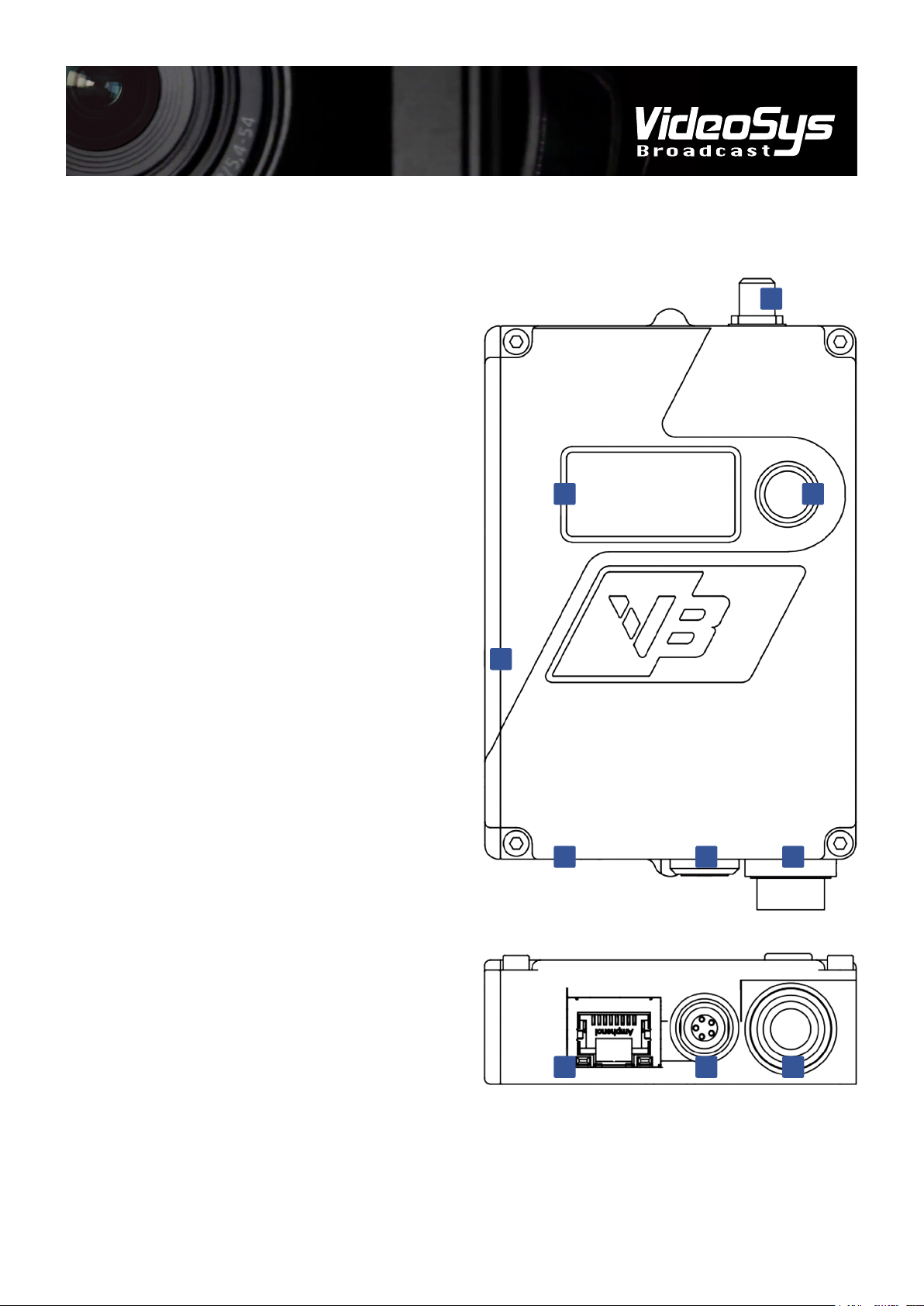
Connecting Components
The camera control RX requires three things, a source of
power, a means of communicating with a camera and an
antenna with which to receive data from the rest of a camera
control system.
Power can be supplied via the generic camera connector, or
the tally connector.
Connection to the camera can be via either the generic
camera connector or via Ethernet using the RJ45 connector.
Principal of Operation
The VideoSys RX is a more than just a data receiver, it emulates a camera manufacturers RCP, allowing for a light weight
communication protocol better optimised for transmission over RF to be used.
Fig 1. A simple Uni-directional camera control setup