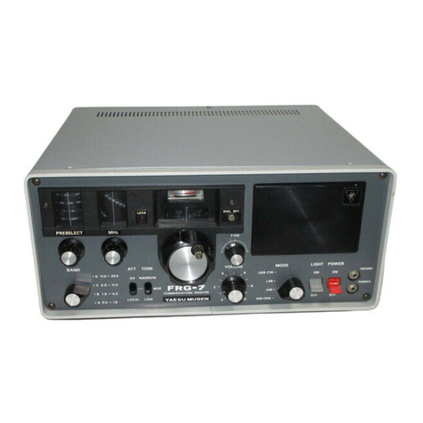
Yaesu FT-560 User manual

INSTRUCTION
MANUAL
YAESU
MUSEN
CO.,
LTD.
TOKYO
JAPAN


SPECIFICATIONS
ИННИИ
еее
и.
SSB
(USB
апа
LSB
selectable)
CW
nn
560
watts
PEP
maximum,
500
watts
CW
AO
1...
e.
oe
e
ns
3.5-4.0,
7.0-7.5,
14.0-14.5,
21.0-21.5,
28.0-30.0
MHz
10.0—10.5(RX
only)
(2
extra
bands
can
be
added)
РАР
AN
After
warmup
100
Hz
for
any
30
min.
СЕ
Се............;.
m
RR
Rm
RR
R
RR
MIL
50
to
120
ohms
unbalanced
Carrier
озеп
A
A
Ap
ТТЫ
Ыр;
Better
than
-40
db
ION...
Better
than
-50
db
at
1000
Hz
RSS
ANS
NR
Better
than
-25
db
EN
....
...
..
..
....
.................
O.5,
V
S/N
20db
at
14
MHz
SSB
EM
uus
"i.
2.4
KHz
at
—6db,
4.2
KHz
at
—
60
db
REM
eee
600Hz
at
—6db,
1.2
KHz
at
--60
db
ЕЕ
A
Со...
id
соо.
ины
ИЛЫ
АЙ
50 db
MEE
S
M
Е
о
о,
yy
1
watt
EE
7
7
eee)
yg
E
EE
RR ER
ш...
8
ohms
Иепе
..
..
......................
АС
117
or
220
volts
at
50/60
Hz
ee
.........:...............
1534”
wide,
64”
high,
1334”
deep
EE
A
ds
ea
RII
approximately
(40
Ibs.)
x
Option


CONGRATULATIONS!
You
have
just
purchased
one
of
the
finest,
high
performance
transceivers
available
to
the
amateur
today.
To
fully
appreciate
the
features,
flexibility,
and
efficient
operating
procedures
available
with
your
new
transceiver,
we
recommend
that
the
in-
struction
manual
be
studied
thoroughly
prior
to
operation.
GENERAL:
The
FTdx560
Single
Sideband
Transceiver
is
a
pre-
cision
built
transceiver
providing
SSB
(USB
and
LSB),
and
CW
modes
of
operation.
This
transceiver
operates
at
a
maximum
input
of
(560)
watts
PEP
for
SSB,
and
(500)
watts
CW
on
all
bands,
80
through
10
meters.
In
addition
to
the
high
output
power
of
the
trans-
ceiver,
many
features
that
have:
previously
been
consid-
ered
extra
cost
options
are
included
as
standard
equip-
100/25KHz
ment
on
the
FTdx560
Standard
equipment
includes
built-in
solid
state
power
supply,
noise
blanker,
fully
adjustable
VOX,
break-in
СУУ
operation,
adjustable
CW
side
tone,
clarifier
control
provides
+
5
KHz
off-set
receiver
operation,
dual
calibration
markers
at
100
and
25
KHz,
10
MHz
WWV
Band,
provision
for
two
additional
transceive
bands
outside
the
amateur
bands
between
3.5
and
30
MHz,
and
front
panel
external
VFO
switching.
ЕУ401
External
VFO
The
companion
FV401
External
VFO
allows
cross-
band
DX
operation
and
has
the
effect
of
providing
the
operator
with
split
frequency,
separate
receiver-trans-
mitter
operation,
controlled
by
VFO
or
X-tal.
The
FTdx560
has
been
designed
to
anticipate
the
amateur’s
future
operating
requirements
and
will
provide
many
hours
of
trouble
free
service.
MARKER
З
art
a=
E
IST
MIX.
GATE
CONT.
3180KHz
(1/2)
FREQ.(MHz)
|
80
9.52
|
|
p
USB
САЯН(05С.
LSB
TONE
40
13.02
LOCAL|OSC.
|
BUFF.
SETIR
|
20
2002
ПЕ
esas
ввдё
[т
——[;
—O
ExT.
VFO
-ІП
12447
СПЕ
КЕ
т
4
|
3178.5KHz
|
3181.5KHz
IOA
3402
|
|
ER
108
3452
ос
35.02
|
250735
RECEIVE
|
—
—
—
TRANSMIT
100
35.52
|
|
ЕТГІ
ММУ
16.02
|
===
RECEIVE
6
|
|
|
BAL.(MOD.
МІС.
AMP
МІС.
1
=|
4
=
|
|
DRIVER
2ND
ç
MIX.
Г.
|
{оке
јално
|
s
Ж
Я
|
ALC
RECT.
RY
TUBE
VOX{AMP.
=
1
ALC
I2AT7
I2AT7
>=
RELAY
[+7
1⁄2)
BLOCK
DIAGRAM
1---

PRINCIPLES
ОҒ
OPERATION
The
block
diagram
and
the
circuit
description
pro-
vides
you
with
a
better
understanding
of
this
transceiver.
The
transceiver
consists
of
a
double-conversion
receiver
and
a
double-conversion
exciter-transmitter.
Receiver
and
transmitter
circuits
use
common
oscillators,
common
crys-
tal
filter,
and
common
IF
stages.
The
low
frequency
IF
is
3,180
KHz.
The
high
frequency
IF
is
pass
band
tuned
to
cover
5,520
to
6,020
KHz.
RECEIVER
CIRCUIT:
A
signal
from
the
antenna
passes
through
the
antenna
relay
and
trap
coil,
(tuned
to
5,770
KHz),
then
to
the
tuned
circuit
and
is
applied
to
the
grid
of
the
RF
ampli-
fier,
УІ,
6BZ6.
;
The
high
frequency
oscillator
injection
signalis
also
fed
to
the
cathode
of
the
first
mixer
from
the
local
oscillator
V2,
6BA6.
The
product
of
the
first
mixer
is
applied
from
the
plate
of
the
tube
to
the
high
IF
pass
band
transformer.
Output
of
this
transformer
(5,520
to
6,020
KHz)
is
ap-
plied
to
the
grid
of
the
second
receiver
mixer,
V203,
6BE6.
When
the
signal
is
applied
to
the
grid
of
V203,
and
the
VFO
injection
signal
is
applied
to
another
grid
of
the
tube,
the
3,180
KHz
difference
product
is
fed
from
the
V203
plate
circuit
to
the
Noise
Blanker
Unit.
The
output
from
V203
is
fed
to
the
base
of
the
IF
amplifier
TR351,
2SC711
and
the
base
of
the
noise
amp-
lifier
TR352,
2SC711.
The
output
from
TR351
is
fed
to
the
crystal
filter
through
the
noise
blanker
diodes
D351
and
D352,
1S1007.
The
diodes
disconnect
the
input
of
the
crystel
filter
each
time
there
is
noise
pulse.
The
diode
switch
is
driven
by
TR354.
The
switching
level
is
adjusted
by
the
noise
blanker
threshold
control
VR351.
D1301
through
D1304
are
diode
switches
which
select
the
crystal
filter
for
SSB
or
CW
operation.
The
600Hz
CW
filter
XF-31C
is
an
optinal
feature
available
at
additional
cost
from
your
dealer.
The
diode
|
switch
selects
the
CW
filter
automatically
when
the
MODE
switch
is
set
to
CW
position.
The
output
from
the
filter
is
applied
to
the
grid
of
the
first
IF
amplifier,
V204,
6BZ6.
The
signal
is
amplified
by
V204
and
V205
and
applied
through
T205
to
the
AGC
rectifier
diodes,
and
the
grid
of
product
detector
V213,
12AU7.
The
beat-frequency
oscillator
signal
which
is
generated
in
V206,
12AU7
is
applied
to
the
cathode
of
V213,
12AU7
and
the
result
is
the
detected
audio
signal.
Output
of
the
AGC
rectifier
circuit
is
applied
to
the
grid
circuit
of
the
RF
amplifier
tube
and
IF
amplifier
tubes
to
control
the
gain
of
the
receiver
automatically
and
prevent
overload-
ing.
Output
from
the
product
detector
is
applied
to
the
noise
limiter
circuit
by
a
switch
on
the
front
panel.
Output
from
the
noise
limiter
circuit
is
applied
through
the
AF
GAIN
control,
VR9,
to
the
grid
of
the
first
AF
amplifier
tube,
triode
section
of
V210,
6BM8.
Amplified
audio
output
of
the
triode
section
is
coupled
to
the
grid
of
the
AF
output
amplifier,
pentode
section
of
V210,
which
drives
the
output
transformer
T1.
TRANSMITTER
CIRCUIT:
The
microphone
input
is
connected
to
the
grid
of
the
first
microphone
amplifier
V208A,
12AX7,
and
then
coupled
to
the
grid
of
the
second
amplifier,
V208B,
the
other
half
of
the
tube.
Output
from
V208B
is
coupled
to
the
beam
deflection
electrode
of
У207,
7360,
through
the
MIC
GAIN
control,
VR-6.
In
the
CW/TUNE
position
of
the
MODE
switch,
out-
put
from
the
tone
oscillator,
V212,
6U8,
is
fed
to
the
grid
of
the
receiver
power
amplifier
tube,
У210.
The
carrier
signal
generated
in
V206,
12AU7,
is
fed
to
the
control
grid
of
V207.
Output
from
the
balanced
modulator
V207
coupled
to
the
grid
of
the
IF
amplifier,
У204,
6BZ6,
through
the
crystal
filter,
XF-201
of
which
the
passband
is
centered
at
3,180
KHz.
This
passes
either
the
upper
or
lower
sideband,
depending
upon
the
sideband
selected
when
the
MODE
switch
is
set
to
carrier
crystal
X201
or
X202.
The
output
from
the
IF
amplifier
is
fed
through
T204
to
the
grid
of
transmitter
VFO
mixer,
V201,
6CB6.
The
plate
circuit
of
the
first
mixer
is
connected
to
the
pass-
band
tuning
transformer
BPF5,
and
converts
the
3,180
KHz
sideband
signal
to
a
5,520
to
6,020
KHz
single
side-
band
signal.
The
passband
tuning
is
so
designed
that
it
provides
excellent
spurious
reduction.
The
output
signal
from
the
passband
network
is
fed
to
the
grid
of
the
second
mixer,
V3,
6AH6,
and
the
high
frequency
injection
signal
from
crystal
oscillator,
V2,
6BA6
is
also
fed
to
the
grid
of
V3.
This
arrangement
converts
the
IF
signal
to
the
de-
sired
transmitting
frequency.
Output
from
the
second
mixer
is
fed
through
a
tuned
circuit
to
the
grid
of
the
driver
tube,
V4,
6GK6
and
amplified
to
a
level
sufficient
todrive
the
final
linear
amplifier,
V5
and
V6,
6KD6s.
Final
output
from
V5
and
V6
is
fed
to
a
pi-section
network
consisting
of
L15
and
PLATE
and
LOAD
capa-
citors.
А
section
of
the
bandswitch
adjusts
the
inductance
of
L15
to
the
correct
value
for
each
band,
and
adds
fixed
amounts
of
capacity
to
the
PLATE
and
LOAD
capacitor
on
the
lower
bands.
Output
from
the
pi-network
is
fed
to
the
antenna
through
the
contacts
of
the
antenna
relay.
Both
the
driver
and
final
stages
are
neutralized
to
ensure
stability.
А
section
of
the
band
switch
selects
the
capa-
citors
to
the
corerct
value
for
perfect
neutralization
on
each
band.
The
ALC
circuit
is
placed
in
the
grid
circuit
of
the
final
tubes.
When
RF
driving
voltage
to
the
final
tubes
becomes
sufficient
to
drive
the
grids
positive,
the
grids
begin
to
draw
current
and
the
signal
is
detected.
This
produces
an
audio
envelope.
The
audio
is
then
rectified.
by
the
ALC
rectifier,
which
in
turn
produces
a
negative
DC
voltage.
The
voltage
is
filtered
by
C61
and
R-29,
which
also
determines
the
time
constant,
and
controls
the
gain
of
V204.
This
system
allows
a
high
average
of

modulation
without
increased
distortion.
The
output
voltage
from
the
second
microphone
am-
plifier,
V208,
is
coupled
through
the
VOX
GAIN
control
to
the
grid
of
V209A,
12AT7,
and
fed
to
the
VOX
recti-
fier.
The
positive
DC
output
voltage
of
the
VOX
rectifier
is
applied
to
the
grid
of
VOX
relay
amplifier
tube,
У209В,
12AT7,
causing
it
to
conduct
current
and
actuate
the
VOX
relay
RL1.
The
relay
tube
is
so
biased
that
the
relay
is
actuated
by
the
VOX
GAIN
switch
in
the
MOX
position.
Contacts
on
the
relay
switch,
—70
volts
DC
muting
and
bias
voltage,
the
metering
circuit
from
receive
to
transmit,
the
clarifier
and
antenna
relay.
The
ANTITRIP
circuit
provides
a
threshold
voltage
to
prevent
the
loud
speaker
output
from
tripping
the
transceiver
into
the
transmit
function.
The
receiver
output
audio
voltage
is
connected
through
ANTITRIP
control,
VRS,
to
a
rectifier.
Negative
DC
output
voltage
from
the
ANTITRIP
rectifier,
connected
to
the
grid
of
the
VOX
tube
V209B,
12AT7,
provides
the
necessary
antitrip
threshold.
ANTITRIP
control
VR8
adjusts
the
value
of
the
antitrip
voltage
threshold
so
that
the
loudspeaker
out-
put
will
not
produce
too
much
positive
DC
output
from
the
VOX
rectifier
so
as
to
exceed
the
negative
DC
output
from
the
antitrip
rectifier
and
cause
V209B
to
actuate
the
relay.
However,
the
microphone
input
will
cause
the
positive
voltage
to
overcome
the
negative
voltage
and
actuate
the
relay.
VR13
provides
coarse
adjustment
for
relay
tube
sensitivity.
Relay
hold time
will
be
determined
by
DELAY
con-
trol,
located
on
chassis
rear
apron.
OSCILLATORS
Тһе
transceiver
contains
5
oscillators.
They
are
the
carrier
oscillator,
the
high
frequency
crystal
oscillator,
the
variable
frequency
oscillator,
the
tone
oscillator,
and
the
crystal
calibrator.
Carrier
Oscillator
The
carrier
oscillator
is
crystal
controlled
at
either
3,178.5
or
3,181.5
KHz,
depending
upon
whether
X201
or
X202
is
selected
by
the
MODE
switch.
The
MODE
switch
disconnects
the
cathode
circuit
of
either
tube
when
not
in
use.
These
crystal
frequencies
are
matched
to
the
pass
band
of
the
crystal
filter,
to
place
the
carrier
fre-
quency
approximately
20db
down
on
the
skirt
of
the
fil-
ter
response.
The
3,178.5
KHz
crystal
frequency
is
shifted
into
the
filter
response
range
to
insert
the
carrier
for
CW/TUNE
operation.
High
Frequency
Oscillator
The
band
determining
oscillator,
V2,
6BA6,
is
crystal
controlled
by
one
of
the
9
crystals
selected
by
the
BAND
switch.
Output
from
the
oscillator
is
fed
to
the
cathode
of
the
receiver
first
mixer
V202,
6CB6,
and
the
grid
of
the
transmitter
second
mixer,
V3,
6AH6.
The
output
fre-
quency
of
this
oscillator
is
always
6,020
KHz
higher
than
the
lower
edge
of
the
selected
band.
The
output
signal
from
this
oscillator
is
the
crystal
fundamental
frequency
for
80
and
40
meters,
but
for
higher
bands,
the
crystal
frequency
isdoudledin
the
plate
circuit
of
the
oscillator.
Variable
frequency
oscillator
The
VFO
uses
a
FET
transistor,
TR401,
3SK22G,
as
the
oscillator,
and
TR402,
first
buffer
and
TR403
buffer
amplifier.
The
VFO
oscillating
frequency
is
8,700
to
9,200
KHz
to
provide
500
KHz
Band
coverage.
Varactor
diode
15145
is
in
series
with
capacitor,
C415
and
is
switched
into
the
circuit
by
the
CLARIFIER
switch
and
relay
contacts
to
shift
the
VFO
frequency.
Output
from
TR403
is
fed
through
the
SELECT
switch
to
VFO
buffer
tube
V211.
Crystal
calibrator
The
100
KHz
crystal
oscillator,TR301,2SC735Y
is
used
for
dial
calibration.
Output
from
the
oscillator,
TR301
is
fed
into
the
25
KHz
multivibrator
which
generates
a
marker
signal
every
25
KHz.
Tone
oscillator
The
tone
oscillator
operates
when
the
MODE
switch
is
in
CW/TUNE
position.
It
is
a
phase
shift
oscillator
operating
at
approximately
800Hz.
The
output
is
applied
to
the
receiver
audio
amplifier
for
sidetone
monitoring
in
CW
operation.
POWER
SUPPLY
The
built-in
power
supply
is
an
all
solid
state
bridge-
type,
delivering
4
different
DC
voltages
and
also
AC
heater
supply
for
all
tubes.
The
power
transformer
has
two
primary
windings
for
operation
from
either
117
or
220
volt
AC
supply.
The
power
amplifier
plate
voltage
(600V
DC)
is
sup-
plied
from
bridge
connected
silicon
rectifiers.
300
volts
DC
is
delivered
to
the
plates
of
the
other
tubes,
and 150
volt
DC
supply
is
provided
through
the
center
tap
of
the
medium
voltage
supply.
Bias
is
supplied
from
a
half
wave
rectifier,
D513,1S1943
The
plate
voltage
for
all
oscillator
tubes
is
regulated
with
a
VR-105
MT,
stabilizer
tube.

сл
.
MODE
.
VOX
GAIN
AF
GAIN
.
CLARIFIER
.
MAIN
TUNING
.
LOADING
‚
PLATE
.
MIC
GAIN
CARRIER
.
PRESELE
USB/LSB:
Side
Band
selection.
CW/TUNE:
Use
transmitter
tune-up
and
code
operation.
Controls
the
VOX
gain
and
functions
for
push
to
talk,
stand-
by
or
manual
operation.
Varies
the
gain
of
receiver
audio
amplifier,
and
noise
blanker
is
connected
at
pull
position.
Varies
the
VFO
frequency
slightly
for
receiver
incremental
tuning.
Controls
operating
frequency.
Tunes
the
output
circuit
of
РІ
network.
Tunes
the
plate
circuit
of
PA
tubes.
Controls
microphone
gain
for
transmitting,
and
carrier
input
for
CW
and
tune-up.
Pretunes
signal
circuits
for
both
transmit
and
receive
condition.
10.
ТТ;
mx
6
О
Selects
operating
Бапа.
Controls
the
gain
of
RF
and
IF
stages.
Main
switch
Selects
the
meter
to
read
PA
cathode
current,
relative
power
output,
or-cathode
current
of
ALC
controlled
stage.
100
KHz:
100
KHz
calibration
25
KHz:
25
KHz
multivibration
NOR:
Operating
frequency
is
controlled
by
main
tuning
dial.
RX-EXT:
Receiving
frequency
is
controlled
by
external
VFO.
.
TX-EXT:
Transmitting
fre-
quency
is
controlled
by
external
BAND
HF
GAIN
.
POWER
.
HEADPHONE
JACK
.
MICROPHONE
JACK
.
METER
.
CALIBRATOR
on.
on.
"
SELECT.
VFO.
AGC
Changes
receiver
AGC
release
time.

RF
OUT
(B
ANT
@
GND
@
ACC
@
6000
Ф
PATCH
DELAY
i
Output
from
driver
stage
may
be
obtained
for
the
use
of
optional
equipments,
such
as
our
FTV-650
transverter.
Coaxial
connector
for
antenna.
Ground
connection.
Accessory
socket.
Pins
|
and
2
shorted
by
ACC.
plug
(11ріп
male
plug)
when
oper-
ating
without
transverter.
Receiver
output
at
600
ohm
imped-
ance
to
be
used
for
phone
ratch.
Speech
input
terminal
for
phone
patch
connection.
Impedance
is
50
kilo-ohms.
Adjusts
"hold-in"
time
of
VOX.
ANTITRIP
RELAY
S-ADJ
ALC
KEY;
VFO
BIAS
802
VFO
POWER
FUSE
FAN
тее
6
00
e
ы
©
0000000
Adjusts
VOX
anti-trip
level.
Adjusts
operating
level
of
УОХ
relay
Adjusts
S-meter
zero
setting.
Adjusts
ALC
limiting
action.
Key
jack
for.code
operation.
Input
jack
for
external
У.
Е.
О.
Adjusts
bias
on
PA
tubes.
Receiver
output
at
80hm
impedance
for
loud
speaker.
Source
for
external
V.
F.
O.
SHORT
plug
(7
pin
male
plug)
should
be
inserted
when
operating
without
external
V.
F.O..
shorting
Pins
3
and
4.
Fuse
holder.
IOamps.
for
117volts,
6amps.
for
220volts
operation.
Power
outlet
for
optinal
cooling
fan.

INSTALLATION
It
is
recommended
that
an
excessively
warm
location
be
avoided.
The
transceiver
should
be
placed
in
a
loca-
tion
that
has
adequate
space
to
permit
free
air
circulati-
on
through
the
cabinet
openings.
І
Тһе
transceiver
should
Бе
connected
to
а
good
ground
by
a
heavy
lead
to
the
terminal
marked
GND
on
rear
apron
of
the
chassis.
It
is
not
recommended
that
a
gas
pipe
or
electrical
conduit
pipes
be
used.
The
ground
lead
should
be
as
short
as
possible.
Impedance
of
the
antenna
is
designed
to
match
a
50
to
120
ohm
load.
Most
commercial
antenna
and
feeders
are
designed
between
50
and
75
ohms.
If
the
impedance
is
far
from
this
value,
an
antenna
matching
device
should
be
placed
between
the
antenna
terminal
and
the
feeder.
OPERATION
INITIAL
CHECK
Prior
to
connecting
the
transceiver
to
power
outlet,
carefully
examine
for
any
visable
damage,
check
that
all
tubes
and
crystals
are
properly
seated
in
their
sockets,
and
check
tuning
controls
and
switches
for
complete
freedom.
Connect
the
speaker
to
jack
marked
8
ohms
on
rear
apron
of
the
chassis,
and
an
antenna
cable
to
the
coaxial
cable
connector.
Make
sure
that
supply
voltage
is
the
same
as
the
voltage
marked
on
the
rear
apron
of
the
chassis
before
connecting
to
power
outlet.
Insert
АСС
plug
(II
pin
male
plugshorting
pins
|
and
2)
into
ACC
socket
on
the
rear
apron
of
the
chassis,
and
check
that
SHORT
plug
(7
pin
male
plug
shorting
pins
3
and
4)
15
inserted
into
VFO
POWER
socket
on
the
rear
apron
of
the
chassis.
RECEIVER
TUNING
Set
the
controls
as
follows:
POWER
OFF
VOX
GAIN
STBY
MODE
Desired
operation
mode
BAND
Desired
Band
MIC
GAIN
Fully
counterclockwise
RF
GAIN
Fully
clockwise
SELECT
NOR
CLARIFIER
OFF
AGC
FAST
Press
the
power
switch
to
ON
position,
then
adjust
the
AF
GAIN
control
until
some
receiver
noise
is
heard
in
speaker.
Peak
the
PRESELECTOR
for
maximum
S-meter
reading,
and
tune
slowly
for
desired
signal.
INITIAL
ADJUSTMENTS
Dial
Calibration:
Set
CALIBRATION
switch
to
100
KHz
position.
Ro-
tate
tuning
knob
to
nearest
100
KHz
mark
as
indicated
on
the
lighted
main
tuning
dial.
An
audio
tone
will
be
heard
as
tuning
knob
is
rotated
through
each
100
KHz
dial
point.
Very
slowly
rotate
tuning
knob
in
the
direction
that
causes
audio
tone
to
decrease
in
frequency,
until
tone
is
just
in-
audible.
(Zero
Beat)
Hold
tuning
knob
firmly
at
this
point
and
rotate
skirt
vernier
dial
-to
zero
position.
The
skirt
vernier
dial
surrounds
the
tuning
knob
and
is
held
in
position
by
a
friction
locking
device.
This
dial
is
easily
movable
by
hand
but
will
retain
its
position
after
adjust-
ment.
The
transceiver
must
be
recalibrated
when
changing
mode
of
operation
to
LSB,
USB,
or
CW.
METER
ADJUSTMENTS:
The
transceiver
features
four
separate
meter
functions;
S-meter,
ALC
(Automatic
Limiter
Control
Indication),
IC
(Cathode
Current
of
Final
Amplifier
Tubes),
and
PO
(Relative
Power
Output
Indication).
These
functions
are
controlled
from
the
METER
switch
on
the
front
panel
and
are
adjusted
for
zero
settings
by
means
of
two
variable
potentiometers
on
the
rear
apron
of
the
chassis.
S-Meter
Adjustments
Set
VOX
GAIN
switch
to
STBY
position,
and
R.
F.
GAIN
control
to
fully
clockwise,
disconnect
antenna,
then
adjust
S-meter
control
on
chassis
rear
apron
until
meter
reads
zero.
Reconnect
antenna.
ALC
Adjustment
When
METER
switch
on
the
front
panel
is
set
to
ALC
position
the
meter
will
indicate
limiting
action.
To
adjust
meter
to
zero,
set
controls
as
follows:
MODE
USB
MIC
GAIN
Fully
counterclockwise
VOX
GAIN
МОХ
If
meter
reads
other
than
zero,
adjust
ALC
control
on
rear
apron
of
chassis
for
zero
indication.
Return
VOX
GAIN
to
STBY
position.
BIAS
ADJUSTMENT
After
warmup,
set
MODE
switch
to
USB,
METER
to
IC,
and
the
VOX
GAIN
switch
to
MOX
for
transmit
condition.
The
meter
will
indicate
PA
plate
current.
The
needle
of
the
meter
should
rise
to
IDLE
position
which
is
approximately
50
ma.
If
plate
current
is
other
than
50
ma,
adjust
BIAS
potentiometer
on
fear
apron.
VOX
ADJUSTMENT
VOX
controls
have
been
preset
for
normal
operation
settings
at
the
factory,
however,
in
the
event
of
V209
tube
replacement
it
may
be
necessary
to
readjust
controls.
Set
ANTITRIP
and
DELAY
control
on
rear
ap-
ron
of
chassis
to
end
of
counter-clockwise
travel.
Remove
microphone
from
mic
jack.
Set
VOX
GAIN
control
to
fully
clockwise
position.
|
Set
MODE
switch
to
USB
ог
LSB.
Advance
VRI3
marked
“RELAY”
clockwise
until
,
relay
activates.
Then,
decrease
slowly
the
setting
of
VR13
counter-clockwise
to
the
point
where
the
transceiver
again
turn
into
receive.

А
'
ј
f
y
QN
CA
TRANSMITTER
TUNING
Set
controls
as
follows:
LOADING
POSITIONS
SELECT
NOR
BAND
LOADING
VOX
GAIN
SIBY
GO
T
NM
Ead
LE:
4
MODE
\
TONE
20
Dr
C
ВЕНЫ
2.5
MIC
GAIN
Fully
counter
clockwise
20
5
AF
GAIN
Normal
listening
level
фей
ali:
mitu
СМ
ual
^
METER
БЕ
|
19666999
CLARIFIER
OFF
10A
вал
сто,
ret
OA
a
MS
y
AR
A
Аы
3
BAND
Desired
band
ШОБ
o.
ест
сес
сөгіс
а»
Э
PLATE
Desired
band
ТОС
ҚЫМ
ҚАРЫМ
heb
3
LOADING
To
position
shown
in
table
DOD.
О
«ММУ!
Ə
PRE-TUNING
1.
Adjust
PRESEL
for
maximum
receiver
noise
level.
2.
Turn
VOX
GAIN
switch
to
MOX
position
with
meter
in
IC
position.
3.
Rotate
MIC
GAIN
control
until
meter
rises
just
above
normal
idling
current.
(50
ma)
4.
Rotate
PRESEL
control
for
maximum
meter
reading.
(Caution:
if
meter
reading
exceeds
0.2
reduce
MIC
GAIN
control).
.
Rotate
PLATE
control
for
minimum
meter
reading.
(Dip
plate).
.
Return
VOX
GAIN
switch
to
STBY.
Тһе
transmitter
is
now
pre-tuned
to
the
desired
frequency.
Final
peak
tuning
is
accomplished
by
carefully
following
the
final
tuning
procedure.
FINAL
TUNING
CAUTION:
EXCEEDING
THE
TIME
LIMITS
NOTED
DURING
FINAL
TUNING
MAY
RESULT
IN
DESTRUCTION
OF,
THE
FINAL
OUTPUT
TUBES.
1.
Set
meter
to
P.O.
position,
VOX-GAIN
to
STBY,
MODE
to
CW/TUNE,
MIC
GAIN
to
10.
2.
Momentarily
set
VOX-GAIN
to
MOX
(ten
seconds
maximum),
adjust
PRESEL
for
maximum
meter
reading.
Return
VOX-GAIN
to
STBY.
3.
Momentarily
set
VOX-GAIN
to
МОХ
(ten
seconds
maximum),
increase
or
decrease
LOADING
slightly
for
maximum
meter
reading.
Return
VOX-GAIN
to
STBY.
4,
Momentarily
set
VOX-GAIN
to
MOX
(ten
seconds
maximum),
adjust
PLATE
for
maximum
meter
reading.
Return
VOX-GAIN
to
STBY.
5.
Repeat
steps
3
and
4
until
maximum
meter
reading
is
obtained.
The
transmitter
is
now
peaked
to
maximum
output.
Return
MIC
GAIN
to
zero,
meter
іо
ІС
position,
and
set
MODE
switch
to
desired
operating
position.
SSB
OPERATION
=
|
Айег
completion
of
tuning
set
МОРЕ
to
LSB
ог
TRIP
control
to
the
minimum
point
to
prevent
the
USB.
Set
the
METER
switch
to
ALC
position.
Set
the
speaker
output
from
tripping
the
VOX.
Do
not
use
more
VOX-GAIN
control
to
MOX
and
adjust
the
MIC
GAIN
VOX
gain
or
more
ANTITRIP
gain
than
T
control
until
the
meter
kicks
up
to
midscale
of
green
Adjust
the
DELAY
control
on
rear
apron
for
suitable
colored
portion
when
speaking
into
the
microphone
nor-
release
time.
'
mally.
Set
the
VOX-GAIN
control
to
desired
operation,
NOTE:
When
meter
is
set
to
IC,
voice
modulation
peaks
МОХ
(manual),
PTT
(push
to
talk),
or
VOX
(voice
con-
will
indicate
250
to
300
ma.
Actual
peak
сш-
trol).
For
VOX
operation,
advance
VOX
GAIN
control
rent,
however,
is
approximately
2
times
the
until
voice
actuates
the
transceiver.
Set the
ANTI-
indicated
value.

СУУ
OPERATION
Using
the
two
contact
jack
supplied
with
the
accessory
pack,
connect
key
as
shown
in
the
illustration.
Most
relay
type
automatic
keyers
can
be
connected
into
the
transcei-
ver
for
break-in
operation
without
modification.
but
when
using
reed
relay
or
transistorized
automatic
keyers
place
390
ohm
resistor
in
series
with
key
line.
TUNING
PROCEDURE
-
CW
Set
up
transceiver
as
described
in
transmitter
tuning
with
adjusting
CARRIER
control
to
desired
power
out-
put
up
to
maximum.
After
completion
of
final
tuning,
install
is
jack
in
rear
apron
of
transceiver.
Set
MODE
switch
to
CW
and
VOX-GAIN
switch
to
MOX.
The
transceiver
is
now
set
up
for
manual
CW
operation.
After
completing
a
trans-
mission
the
VOX-GAIN
switch
must
be
returned
to
STBY
position
for
receive
operation.
For
break-in
opera-
tion,
simply
advance
VOX-GAIN
control.
SIDETONE
ADJUSTMENT
CW
sidetone
level
may
be
adjusted
by
rotating
the
tone
level
potentiometer
(VR
203)
located
on
the
main
circuit
board
under
the
top
cover.
NOTE:
Do
not
disturb
setting
of
adjacent
paint
marked
controls.
SERVICE
INSTRUCTIONS
WARNING
Dangerous
voltages
are
present,
therefore
extreme
care
is
essential.
Be
sure
that
all
power
is
disconnected
before
working
on
the
chassis.
Check
the
high
voltages
in
the
capacitors
by
shorting
the
high
voltage
line
to
ground
with
an
insulated
screw
driver.
The
transceiver
has
been
aligned
and
calibrated
at
the
factory
with
proper
test
instruments
and
should
not
require
realignment.
Service
or
replacement
of
a
major
component
may
re-
quire
subsequent
realignment,
but
do
not
attempt
to
make
an
alignment
unless
the
operation
of
the
transceiver
is
fully
understood.
TEST
EQUIPMENT
REQUIRED
A
signal
generator,
a
vacuum
tube
volt
ohm
meter
with
RF
probe,
a
general
coverage
communication
re-
ceiver,
and
a
300
watt
dummy
load.
VOLTAGE
AND
RESISTANCE
MEASUREMENTS
The
table
lists
voltages
and
resistance
at
all
tube
sockets.
These
values
are
measured
with
а
VTVM
with
all
tubes
installed
in
their
respective
sockets.
All
measurements
should
be
made
from
socket
pins
to
ground.
Adjust
transistor
voltage
regulator
to
exactly
9
volts
with
VR-202
on
the
printed
board.
Measure
voltage
at
junction
of
R294
and
R295.
TRANSMITTER
ALIGNMENT
1.
Disconnect
the
high
voltage
(600
volts)
by
unsolder-
ing
the
lead
at
rectifier,
and
also
the
screen
voltage
by
unsoldering
the
connection
at
pin
3
of
the
two
tube
sockets.
(V5,
V6)
2.
Connect
VTVM
КЕ
probe
to
pin
5
of
V5.
3.
Set
the
MODE
switch
to
USB
or
LSB,
and
the
VOX
GAIN
switch
to
MOX
position.
Adjust
car-
rier
balance
potentiometer
VR
201
on
the
main
print
board
for
minimum
VTVM
indication.
4.
Advance
MIC
GAIN
control
two
positions,
and
turn
the
MODE
switch
to
CW/TUNE.
5.
Adjust
PRESEL
control
for
maximum
VTVM
read-
ing.
6.
Adjust
the
MIC
GAIN
control
during
transmitter
alignment
to
keep
VTVM
reading
at
15
volts
to
avoid
saturation
of
the
circuits.
7.
Start
with
upper
slug
of
T203
nearly
out
and
peak
for
peak'VTVM
reading.
8.
Start
with
both
slugs
of
T204
nearly
out
and
adjust
both
slugs
for
peak
VTVM
reading.
9.
Set
the
BAND
switch
to
the
80
meter
band,
the
main
tuning
dial
to
the
center
(250
KHz),
and
the
PRESEL
control
at
center.
Adjust
the
slugs
of
L901
4
L1001
for
peak
VTVM
reading.
Adjust
the
slugs
on
all
ap-
propriate
bands
from
40
to
15
meters
using
the
same
procedure.
Set
the
BAND
switch
to
10B
and
the
main
tuning
dial
at
upper
edge,
and
adjust
L905
and
L1005
for
peak
VTVM
readings.
”
—
8
——

1
13.
14.
г
10.
Disconnect
the
VTVM
from
pin
5
of
У5,
and
con-
nect
it
to
pin
2
of
V202.
Set
the
BAND
switch
to
10D
and
adjust
slug
L3
for
peak
VTVM
reading.
Set the
BAND
switch
to
10С
and
adjust
the
TC1101
for
peak
VTVM
reading.
Adjust
TC1102
for
10B,
ТС
1103
for
10A,
TC1104
for
15
and
TC1105
for
the
20.Set
the
band
switch
to
40
and
adjust
L4
for
peak
VTVM
reading.
For
80
meter
band,
adjust
TCII06
for
peak
VT
VM
reading.
Disconnect
VT
VM.
‚
It
is
not
recommended
to
align
BPF5
passband
net-
-
work
unless
proper
measuring
instrument
is
available.
.
Turn
the
FUNCTION
switch
to
OFF.
Restore
un-
soldered
PA
screen
grid
and
high
voltage
wire.
Connect
the
transceiver
output
to
a
50
or
75
ohms
dummy
load.
Set
the
main
tuning
dial
at
center,
and
tuneup
the
transceiver
on
80
meter
band
as
described.
Adjust
MIC
GAIN
control
setting
to
keep
PA
current
less
than
100
ma.
Readjust
L1001
for
peak
meter
reading.
Readjust
L1001
to
L1005
for
appropriate
BAND
settings.
Tune
the
transceiver
to
maximum
output
at
14,350
Кс.
To
measure
spurious
radiation,
use
the
S-meter
of
another
receiver
and
tune
it
to
14,520
Кс
where
a
spurious
signal
can
be
heard.
Adjust
TC-205
for
minimum
S-meter
reading
without
decreasing
power
output
of
the
transceiver.
Adjust
L17
апа
L19
for
minimum
S-meter
reading.
TRANSMITTER
SIGNAL
LEVEL
The
following
table
shows
voltage
measuring
points
and
normal
signal
levels.
Before
making
measurements,
set
MODE
switch
to
CW
and
unsolder
the
lead
from
pin
3
of
V5,
and
V6
sockets.
Set
the
VOX-GAIN
switch
to
MOX.
Plug-in
key
to
key-Jack
and
close
key
to
measure
the
signal
level.
TEST
POINT
FREQUENCY
V207
—pin
3
3.178
5
KHZ
V201
—
pin
1
Variable
ey
UI
pin
1
V207
—
pin
7
371785]
KHZ
V204
—
pin
1
Suit
Sus
KHZ
V204
—
pin
S
IZS
би
KHZ
Variable
IF
V3
Transmit
frequency
5
V201
—
pin
5
—
pin
5
5
V5
—
pin
Transmit
frequency
Voltages
given
in
the
table
are
nominal
and
may
vary
FINAL
AMPLIFIER
NEUTRALIZATION
When
replacing
the
final
amplifier
tubes
it
may
be
necessary
to
reset
the
bias
to
50
ma
and
check
neutraliza-
tion.
Using
the
procedure
outlined
below
will
guarantee
maximum
output
and
long
tube
life.
CAUTION:
HIGH
VOLTAGES
ARE
PRESENT
ON
UNDERSIDE
OF
CHASSIS.
USE
GREAT
CARE
WHILE
MAKING
ADJUST-
MENTS
WITH
WIRING
EXPOSED.
В
Locate
TC-1
the
neutralization
variable
capacitor
shaft
on
the
underside
of
chassis
near
the
last
band-
switch
wafer,
in
the
final
amplifier
section.
2.
Connect
antenna
to
dummy
load,
set
meter
to
I.C.
X-tal
frequency
selected
.
Check
final
amplifier
bias
in
upper
or
lower
Side
Band
position.
If
meter
indicates
other
than
50
ma,
reset
bias.
Tune
up
the
transceiver
in
the
center
of
the
15
meter
band.
.
After
tune
up
place
meter
in
І.С.
position,
Mode
switch
in
Tune
position,
and
advance
Mic
Gain
until
meter
reads
150
ma.
Rotate
Plate
tuning
control
and
observe
dip
as
indi-
cated
on
meter.
(NOTE:
If
dip
is
not
prominent,
re-
duce
loading
control
slightly
for
better
indication).
As
the
Plate
control
is
rotated
the
meter
should
rise
equally
and
smoothly
on
either
side
of
maximum
dip
indication.
Determine
which
side
of
the
dip
rises
abruptly.
Set
Plate
control
slightly
to
this
side
of
dip
keeping
the
meter
reading
below
200
ma.
Using
a
non-metallic
tuning
wand,
rotate
neutraliza-
tion
capacitor
shaft
very
slightly
in
the
direction
which
reduces
the
current
shown
on
the
meter.
Repeat
steps
7
and
8
until
the
meter
indicates
a
smooth,
equal
rise
on
either
side
of
the
maximum
dip
point.
RF
VOLTAGE
1
volt
име
(EUNCUON
BY
SW)
O.5-1
volts
5.5
volts
0.02
volts
3.0
volts
9.0
volts
10.0
volts
33.0
volts
=
20%

RECEIVER
CIRCUIT
ALIGNMENT
When
the
transmitter
circuits
are
aligned.
the
only
alignment
remaining
for
the
receiver
circuits
are
the
last
IF
stage
transformer
T205,
T351
through
T353
IF
trans-
formers
in
the
noise
blanker
unit,
antenna
input
trans-
former
1.801
to
1.805,
trap
coils
L806,
1906,
123
and
S-meter
zero
set.
1.
Connect
signal
generator
output
to
the
antenna
ter-
minal.
Set
the
BAND
switch
to
80
meters,
and
receive
3,750
Kc
signal
from
signal
generator.
Adjust
PRE-
SEL
control
for
peak
S-meter
reading.
Adjust
L801
for
peak
S-meter
reading.
Adjust
coils
L802
to
1.805
at
7,250,
14,250,
21,250,
29,000
KHz
respectively
for
peak
S-meter
reading.
2.
Tune
the
receiver
circuit
to
7,100
KHz
incoming
sig-
nal,
and
leave
controls
as
is.
Apply
5,920
KHz
signal
generator
output
to
antenna
terminal.
Adjust
1,806,
L906,
for
minimum
S-meter
reading.
Then
tune
the
receiver
to
7,500
KHz
and
adjust
L23
same
as
above
at
5,520
KHz
signal
generator
output.
3.
Tune
the
receiver
to
incoming
signal
on
any
band,
and
adjust
slugs
of
Lower
dug
of
T203
and
slugs
of
T205
.T351,
T352
and
T353
for
peak
S-meter
reading.
NOISE
BLANKER
CIRCUIT
ALIGNMENT
The
blanking
level
of
the
noise
blanker
is
determined
by
the
THRESHOLD
control
VR351
and
the
noise
am
plifier
stage
transformer
T354.
1.
Connect
a
signal
generator
output
to
the
antenna
ter-
minal,
and
tune
the
receiver
to
the
signal
generator
frequency
with
AGC
switch
OFF
position.
Connect
VTVM
DC
probe
between
the
test
point
(TP)
on
the
noise
blanker
circuit
board
and
ground,
then
adjust
T354
for
peak
УТУМ
reading.
2.
With
the
noise
blanker
OFF
position
(i.e.
АҒ
GAIN
control
at
push
position),
tune
the
transceiver
to
in-
coming
signal
provides
8
to
9
S-meter
reading
on
any
band.
Adjust
the
blanking
threshold
potentiometer
VR351
until
the
S-meter
reading
decreases
one
(1)
S-
unit
when
the
noise
blanker
is
placed
into
the
circuit
by
pulling
AF
GAIN
knob
off.
RECEIVER
SIGNAL
LEVEL
The
following
table
shows
test
points
and
nominal
signal
level
to
produce
S-9
reading
on
S-meter.
SIGNAL
GENERATOR
SIGNAL
GENERATOR
SIGNAL
GENERATOR
CONNECTION
POINT
FREQUENCY
OUTPUT
LEVEL
V205
—
pin
1
3,180
KHz
100
db
V204
—
pin
1
3,180
KHz
75
db
V203
—
pin
7
5,770
KHz
77
db
V201
—
pin
1
5,770
KHz
50
db
М1
--ріп
1
14,255
KHz
47
db
Antenna
Terminal
14,255
KHz
34
db
Oscillator
injection
voltages
V213
—
pin
7
3,178.5
KHz
4
volts
V203
—
pin
1
Variable
3
volts
V202
—
pin
1
Crystal
Selected
1-2
volts
The
receiver
was
tuned
to
14,255
KHz
for
these
measurements
and
the
test
signal
injected
at
indicated
test
points.
Signal
generator
output
levels
are
taken
from
signal
generator
attenuator.
All
values
are
nominal
and
may
vary
=
20%
without
degrading
performance.
|
|
|

TROUBLE
SHOOTING
GUIDE
DEFECT
PA
idling
current
unstable:
Insufficient
load:
Insufficient
carrier
suppression:
Distorted
transmitted
signal:
Insufficient
drive
or
no
drive:
Low
receiver
sensitivity:
VOX
unstable:
ке
рО
Ба
еее
(PB-1120A)
R362
vR35I
R35:
2SK34E
L353
250uH
PULSE
AMP
Los
TR353
POSSIBLE
CAUSE
Defective
V5
and
V6.
Defective
Bias
supply
including
bias
potentiometer.
PRESEL
improperly
tuned.
BAND
switch
improperly
set.
Antenna
not
resonant
at
frequency.
Defective
antenna
or
transmission
line.
V3,
V4,
V5,
V6
defective.
Defective
rectifier.
Defective
V207.
Carrier
balance
control
improperly
set.
Defective
crystal
Х201
or
X202.
Carrier
frequency
improperly
set.
Excessive
MIC
GAIN
adjust.
V7
defective.
D2,
D3
defective.
Incorrect
neutralization.
Defective
rectifier.
Defective
V204,
V201,
V3,
V4,
V5.
Defective
crystal.
.
Antenna
relay
back
contacts
defective.
Defective
V1,
V201,
V203,
V204,
V205.
Defective
V209.
Improper
setting
of
VOX
GAIN
and
ANTITRIP
controls.
x
L35)
тн
NN,
R352
22K
c355
0.01
en
|
C367
ЮОР
0353
151007
C364
0.01
R357,
33K
NOISE
BLANKER
CIRCUIT
DIAGRAM

RESISTANCE
CHART
5
6
7K
[ток
ок
|
10K
WOK
|
7K
је
59
0
0
TUBE
6BZ6
6ВА6
6AH6
6GK
6
6KD
6
6KD
6
VRIOSMT
[10K
|
0
6CB6
|
6СВ6
6ВЕ6
6В76
6ВА6
12407
7360
Ый
ЕУ
АТ
6BM8
6BA
6
6U
8
РА
+
2
|
(<>
o| 9|
=
9| 9|
o| 9|
S9!
9|
9|
<>)
Ке») Ие»)
ol
o
ojoj
+
8|8
|
tt
ro
я
яя
:
e
|
[x|8
e
CW6US
TUNE
ACCESSORY
SOCKET
CONNECTION
Pin
1.
6KD6
Heater
8.
Ground
2.
63
Volt
AC
9,
Relay
contact
open
for
3.
+150
Volt
DC
receive
and
close
to
4.
4-300
Volt
DC
ground
for
tsansmit
OOS
5.
+600
Volt
DC
10.
Relay
contact
open
for
6.
-100
Volt
DC
transmit
and
close
to
QU
(7)
T
АЕС
ground
for
receive.
6)
Ш,
6.3
VINA
G
OJO
NOTE:
ACCESSORY
SOCKET
IS
WIRED
TO
USE
TRANSVERTOR.
WHEN
TRANSVERTOR
IS
NOT
USED,
ACCESSORY
PLUG
MUST
BE
IN
THE
SOCKET,
OTHERWISE,
6KD6
HEATERS
ARE
NOT
CONNECTED
TO
POWER
SUPPLY.
KEY
AND
MICROPHONE
CONNECTIONS
CONNECTION
CONNECTION
FOR
MOX
OPERATION
—
12
—
^

бе.
|
er
=
ү
Sy
Lt
lee
LXVZI
zn
T
T
eme
El
о
Ево
EN.
0
-=
09
|
$1
0961
=:
===!
ЕА.
6
У
с
0€
=
|
o8
0
0
£1
=
08
ПУ
Ст
А
|
A
S£
|
COIL
|
OSI
|
a
0
SE
=
9УЯ9
|
|
|
Е
|
Li
SII
|
9“!
|
te
0
EN
-
9789
|
06—
|
04
|
ost
0
a
=
=
9389
|
1
t
4
=
0
|
ost
|
osi
|
о
52
-
|06—
9499
:
š
EG
s
І
|
=
Д
|
яи
0021-55
9829
0
О
ВИСИ
0
0
|
со
LIASOTHA
T
Е
+
0
1901
0
Jos=|-0
0
o
los=|
о
[
ои
|
о
Lu
9039
DE,
U
DEE
а
Eus.
о
—[-
о
өн
|20
|
Sy
9
059
o
|
док
|
ose
2
0
|
0
-
01
9499
а
E,
x
MS
tr
|
691
|
ose
0
ee
0
=
9НУ9
|
o
|
sor
|
sor}
о
|
52
0
-
9УЯ9
-
—
4
0.
[som
ее
ЕЈ
е
9289
1
a
ET
c
|
aanı
u
и
|
0l
6
8
L
9
ç
#
€
c
I
(A)
Od
(A)
эа
(asn)
LINSNVAL
JYVHI
ADVL
ПОЛ
(asn)
IAIIIIA
—
13
—

361,
364,
365,
406,
407,
409,
412,
413,
421,
1301—1304
39,
42,
114,
372,
СЕКАМІС
DISC
374,
2129
SOoWV
0.047,F
351
CERAMIC
DISC
SOOWV
10000PF
CERAMIC
DISC
SOOWV
4700PF
CERAMIC
DISC
SOOWV
0.01
uF
C-CAPACITOR
240,
2125
DIPPED
MICA
500
WV
ІРЕ--0,5РЕ
|
DIPPED
MICA
500W
V
2РЕ
+0.
5РЕ
12
DIPPED
М!СА
li
5ООУУУ
ЗРЕ--0,5РЕ
DIPPED
МІСА
147,
8.1523,
2426.
27.
500W
V
SPE
EO
SBE
|
25
21037
38
40
4i.
DIPPED
MICA
|
423
44.49,
50,
52:
55=
500W
V
1ОРЕ
+
10%
60,
69:
70;
72,
77,
83;
DIPPED
MICA
1
102.
108,
202.
203.
206,
500
WV
15РЕ
+
10%
208.
213.
214
221
222,
DIPPED
МІСА
AAA
A
2818285,
500
WV
20P
F
+
10%
238,
242,
244, 248, 249,
DIPPED
MICA
|
252,
253,
256,
2592261
500W
V
30PF+10%
|
262,
264,
274,
275,
276,
DIPPED
МІСА
284,
286--297,376,403,
500W
V
40P
F +
10%
414,
513
DIPPED
MICA
63,
64,
501
—
504,
500
W
V
5ОРЕ
+
10%
509~
512
DIPPED
MICA
107
_500W
V
60P
F
+
10%
DIPPED
MICA
500W
V
70P
F
+
10%
DIPPED
MICA
500W
V
80P
F
+
10%
3,
6,217,219,273,
367,DIPPED
MICA
368,
370,
371,
408,
500W
V
100PF
+
10%
1005,
1104,
2122
AAA
352,
358,
362, 366, 801,
2100121015
2102
30
DIPPED
MICA
500WV
180PF
+
10%
DIPPED
MICA
_
500wWV
200PF
--
10%
DIPPED
МІСА
500W
V
250P
F
+
10%
DIPPED
MICA
500W
V
300P
F
+
10%
DIPPED
MICA
500W
V
400P
F
+
10%
DIPPED
MICA
500W
V
470P
F
+
10%
DIPPED
MICA
5ООУУУ
65ОРЕ
--
10%
DIPPED
МІСА
SOOWV
1000PF+10%
DIPPED
MICA
500WV
2000РЕ
+
1024
75
DIPPED
МІСА
ІКУУУ
20P
F
+
10%
71
DIPPED
МІСА
IKWV
1000PF
+
10%
MICA(CMLI)
ІКУУУ
1ОРЕ
+
10%
32
MICA(CML1)
IKWV
50P
F
+
10%
25
МІСА(СМІ
1)
ІКУУУ
100PF
+
10%
47
MICA(CM3
5)
1.5KWV
300PF+10%
48
MICA(CM3
5)
I.SKWV
_
500РЕ
+
10%
86
MICA(CM3
5)
l.5KWV
1000РЕ
+
10%
46
MICA(CMBS)
3K
WV
1000РЕ
--
10%
282
363
T
85,
269,
283
81,93,
1004,
2109
11,74,89,98,101,110,
234,246,281,1107
212527774902;
1105,
2116,
82,
243,
1002,
1305
—
1308,
2103,
2104,
2105,
2121,
22672219:
2128,
2132
33,
279.
907,
1003,
1102
34,
278
13,88,96,304,305,308,311
313,802,805,904,2108
807,
903
CERAMIC
1.
4KTVDC
CERAMIC
DISC(AL)
1.4KTVDC
0,01
uF
29%
FEED
THROUGH
BYPASS
5ООУУУ
—
1000РЕ
CERAMIC(TC)
NPO
5ООУУУ
8РЕ
+0.
5РЕ
CERAMIC(TC)
NPO
500WV
IOP
F
+
10%
CERAMIC(TC)
NPO
500WV
20PF
+
1024
СЕКАМІС(ТС)
МРО
500W
V
82PF
+
10%
CERAMIC(TC)
N750
500W
V
4PF+0,5PF
CERAMIC(TC)
N750
500W
V
IOP
F
+
10%
CERAMIC(TC)
N750
500WV
20PF
+
10%
CERAMIC
RDA30
3KTVAC
ЗОРЕ
+
10%
CERAMIC
RDA40
ЗКТУАС
280PF
+
10%
ЕГЕСТЕОГҮТІС
16УУУ
ІШЕ
ЕГЕСТЕОГҮТІС
16УУУ
СЕС?
ЕГЕСТЕОГҮТІС
16УУУ
104F
ELECTROLYTIC
16WV
100
uF
ELECTROLYTIC
16УУУ
4704Е
ELECTROLYTIC
16УУУ
1000
Е
ELECTROLYTIC
25WV
104
F
97
ELECTROLYTIC
25WV
2204F
ELECTROLYTIC
25WV
470
uF
ELECTROLYTIC
SOW
V
104F
ELECTROLYTIC
160WV
3.3u4F
ELECTROLYTIC
160WV
104F
ELECTROLYTIC
160WV
224F
ЕГЕСТЕОГҮТІС
250WV
10МЕ
DISC(AL)
4700PF
:'°%,
-—À
223, 226,
230,
232
241,
354,
804,
901
302,
803,
1103
ШО
-
100%.
=
де
415
DIPPED
MICA
500W
VY
150PF
+
10%
84,
87,
258,
353,
410,
41-1
35,
79,
236, 301,
310
29,
94
2130
14,
806
401,
402
004,255,257,260,268
4,
205,
209, 227,
251,
306,
307,
2155
303,
405
375
299
514
-Г
006
298
270
2131
211
0721171
65,
66,
272,
2127
45
MICA(CMBS)
3KWV
=
5000РЕ
+10%
373
CERAMIC
DISC
SOW
v
1000РЕ
+80%
—
20%
2113
003,
005,
309,
312,
355256,
357,
359,
CERAMIC
DISC
SOW
V
2200P
F
+80%
—
20%
CERAMIC
DISC
SOW
V
0,01
uF
+80%
-20%
ELECTROLYTIC
350WV
224F
ELECTROLYTIC
350WV
47u4F
ELECTR
I
400WV
474uFx3
[2
9
۷
100
иЕ
5ООУУУ

113
METALIZED
PAPER
160WV
0.12
F
+
20%
METALIZED
PAPER
160WV
0.47
uF
+
20%
2122
2123
306,
1302,
1306
1304,
1305,
SS,
304:
2120
MELALIZED
PAPER
220WV
AC
14F+20%
‚
36
PAPER
600
W
V
0.047
uF
+
20%
5,
14,
45,
236,
238,
240,
241,
243,
245,
246, 248,
249,
250,
259,
268,
278,
291,
292,
2104
61,
250
MYLAR
FILM
010
SOW
v
0.047
мЕ
+
20%
263,
280
MYLAR
5ОУУУ
FILM
0,1uF+20%
369
MYLAR
FILM
12,
202, 205,
208,
210,
215,
220,228,
252;
256;
261,
266,
290,
302,
309,
402,
405,
515,
2106,
009
SOW
v
0.224
F
+20%
287
237
FILM
SA
0-474Е
+
2026
|
MYLAR
5ООУУУ
TC-TRIMMER
CAPACITOR
203,
204,
205,
1101
—
1109
CERAMIC
206
~
209
301
401
VC-VARIABLE
AIR
CAPACITOR
(PRESELECT)
(PLATE)
ww
257,
CO,
2278
2,
226,
254,
263,
265,274,
299,
501
—
508,
601, 602,
22
w
1⁄
w
2100:2101532103/2109;
2126
ECVIZW20P32(20PF)
CERAMIC
ECVIZWAOP32(40PF)
|
2110
2
290,267;
285
225
55
W
55
w
IMQ
2.2MQ
+
CERAMIC
DI
I203
SOPE
AIR
55
w
JBM
224
23:025
WwW
5.6MQ
+
1
W
269
=
275
TSN=
150C
ЗОРИЕ
AIR
513
1W
2209.
1W
4.7KQ
+
218
1
W
5.6KQ
+10%
ОСОРЕ
AIR(SPLIT
STATOR)
516
1W
22KQ
10%
005
IW
33KQ
102%
ЖАЙ
TOC
ОРЕХ...
5
ЕСТЕ
1
W
100KQ
+
10%
18
2W
S.IKQ
+10%
B565A118
39;
2W
33KQ
+10%
ТА
—
270P
16,
3W
47KQ
+10%
(LOADING)
(VFO)
an
ECV2HA43A44
C521A112
SIT
17
4W
5.62
--
10%
5w
4.7KQ
+
1026
R-RESISTOR
356
1⁄4
W
око
SW
27KQ
+10%
SW
33KQ
10%
14
w
22KQ
355
359
20W
1.5KQ
10%
м
w
ко
20W
1⁄4
w
10082
4KQ
+10%
METER
SHUNT
34
w
33KQ
+
1⁄4
w
4709
P
TH62BM220M
(222)
VR-VARIABLE
RESTISTOR
м
w
100KQ
ЕУНВОА515В53
оков
iW
2.7KQ
EVCBOAS20C
14
IOK2C
1⁄4
w
3.3K9
EVCBOGS20B
13
IKQB
with
SWITCH
56
873299
26
№
5.69
E
VL.S3A
A00B53
SKQB(TRIMMER)
35
W
109
282
iW
220
EVFKIASAS54B55
SOKQA
J
SOOK
S2
В
(GANG)
21,
24,
36, 39,
42,
44,221
156
w
569
EVCBOGS20A
55
5ООКОА
with
SWITCH
S
HO
A
SS,
212,
216022803.
310
MW
1002
203
MW
1200
EVHBOASISASS
SOOK
Q A
EVF93QF11653
5ООКОА
with
PUSH
SWITCH
К5
277;
279,411,
2125
WwW
2209
10
EVWJOASISBSI
509В
410
55
w
270Q
11
EVCBOAS15B
24
20KQ2B
364,
403,
406
156
W
3300
12
ЕУСВОА$15В
36
3MQ
B
7,
288;
294
55
w
4709
13
ЕУСВОА515В33
3KQB
293
55
w
5609
2114
ww
680Q
14,
201
EVLS3AA00B53
SKQB(TRIMMER)
202
EVLS3AA0OB
13
IKQB(TRIMMER)
4:68:11.
19:
20,
201,
204,
207,
209,
219,
229,
230,
235, 237,
244, 280,
289, 295,
440,
407,412,
2121,
006,
60
1⁄4
w
1K9Q
S00KQB(TRIMMER)
Ë
203
EVLS3AAO0B55
301
EVLS3AAOOB
14
10KQ2B(TRIMMER)
351
SRI9ROOI
2.2KQ
B
(TRIMMER)
L-INDUCTOR
003
WwW
1.5KQ
+10%
1.
247.212.
352,
358,
594,
403
MICRO
2504
H
INDUCTOR
19.
2531
262,
:
272,
20]
295.
2102
ww
2.2KQ
+10%
CHOKE
COIL
2504H
CHOKE
COIL
2004H
258,
296,
004.
2127
1⁄
w
3.3KQ
+
10%
CHOKE
COIL
300uH
247, 260,
305, 307,
2113
1⁄4
W
4.7KQ
+
10%
CHOKE
COIL
5004H
37,4
007,008
286
408
WwW
5.1KQ
+
10%
355
CHOKE
СОШ.
ImH
55
М
22
W
S.6KQ
+1026
8.2KQ
+10%
001
CHOKE
COIL
2mH
302
CHOKE
COIL
4mH
22,
47,
276,
283, 301, 308,
34W
401,
514,
1301,
1303,
2105,
2107,
2112
213,
286
211, 217,
242,
409,
10KQ
+
10%
T-TRANSFORMER
A.
F.
OUTPUT
55
w
1⁄4
W
ISKR
+1022
22KQ
+
10%
=>
5
POWER

CH-A.F.
CHOKE
COIL
|
35.52
7
IH
125mA
16.02
»
V-VACUUM
TUBE
HC—6/U
3181.5KHz
6AH6
"
3178.5
»
6BA6
|
HC—
ТЗТ
100.»
6BE6
XF-CRYSTAL
FILTER
6BM8
ХЕ
SA
2.4KHz
6BZ6
XE
SIC
600Hz
6CB6
-
RL-RELAY
6GK6
.
201
RAB—
1000—11
6K
D6
E
6U8
[ЙК
PB-PRINTED
CIRCUIT
BOARD
DAT,
PBI001
—2
GENERATOR
12AU7
РВ1002
CALIBRATOR
PANT
PB1004—2
POWER
SUPPLY
7360
PB1007
x3
COIL
ASS'Y
VRIOSMT
PB1022A
TRIM.
САР.
ASS'Y
VS-VACUUM
TUBE
SOCKET
|
РВ1056
V.
E
СИ
C
<
В0203--2
РВ1058
B.
P.
F
201792050244
S
=
80993259
|
РВІО59
В.
Р.
Е
209.
21035212
S=B1307=2
|
PB1065
CARR.
SHIFT
206—208.
213
S-Bj3022
|
РВ1072
DIODE
SWITCH
TEE
Т5102С01
PBII20A
.
NOISE
BLANKER
7
TS102C04
S-SWITCH
4
Т5103С01
1
(BAND
SELECT)RS—
13
—
13—11
TR-TRANSISTOR
2.5.6.7
sS-H-22
9
202,
403
3SC372Y
4
(MODE)
ESR—E283R20Z
201
25С504
8
(POWER)
WD
—
3001
301—304,
001
2SC735Y
J-RECEPTACLE
AND
JACK
402
2SKI9G(FET)
SG7701
401
3SK22G(FET)
Не
Ас
бр
КО,
CN7017
3512352.
354
стр
180239
353
2SK34E
(FET)
SA602B
D-DIODE
SB0821
401
15145
(VARACTOR)
516303
215
15331
(ZENER)
dl
217
15334
(ZENER)
SH3601
216.
356
15336
(ZENER)
NATA
CN7017
Г
204,
212.
1301—
(304,
181007
(
SH3001
002,
351-2355
|
JPL259
2,
3,
202,
203,
209, 210,
151941
PA602B
213,
2184514
517302
4,513
151943 515908
5.
S09
—
512,
001
151944
PL-PILOT
LAMP
501--508
10D10
i
І
8У
015АМР
X-CRYSTAL
OSCILLATOR
PLH-PILOT
LAMP
HOLDER
HG
=18/U
9.52MHz|_1,
NO.
3512
13.02
F-FUSE
20.02
ТОА
МР.
22:02
FH-FUSE
HOLDER
34.02
S
—
NI00I
34.52
M-METER
35.029
ӨЕР,
MK-—45A
ImA
>
159)
°
SE
кај
кај
һә
—|ol!-*
O|w
о:
[SS
кај
кај кај
UI
–
OPTIONAL
EQUIPMENT
Тһе
FTdx560
Transceiver
may
be
fited
with
an
additional
narrow
band
filter
for
the
expert
CW
operator.
The
CW
filter
is
available
from
your
dealer
on
special
order
and
may
be
easily
installed
by
the
amateur.
CW
filter
characteristic
provides
600Hz
bandwidth
and
is
selected
automatically
when
the
Transceiver
mode
switch
is
placed
in
the
CW/TUNE
position.
When
the
mode
switch
is
placed
in
either
SSB
position,
the
normal
2.4
KHz
SSB
filter
is
again
inserted
in
the
circuit.
Table of contents
Other Yaesu Receiver manuals

Yaesu
Yaesu FT-1000 User manual
Yaesu
Yaesu VR-500 User manual

Yaesu
Yaesu FT-2500M Administrator guide

Yaesu
Yaesu VR-5000 User manual

Yaesu
Yaesu FR-100-b User manual

Yaesu
Yaesu FR-101 User manual

Yaesu
Yaesu FRG-7700 Manual

Yaesu
Yaesu FT-901DM User manual

Yaesu
Yaesu FRG-9600 User manual

Yaesu
Yaesu VR-120D User manual