Videotec IR20 spot User manual

ITALIANO ENGLISH
FRANCAIS DEUTSCH
DESCRIZIONE 1
INSTALLAZIONE 1
SPECIFICHE TECNICHE 2
DESCRIPTION 3
INSTALLATION 3
SPECIFICATIONS 4
DESCRIPTION 5
INSTALLATION 5
SPECIFICATIONS 6
BESCHREIBUNG 7
INSTALLATION 7
TECHNISCHEN DATEN 8
Illuminatore infrarosso Infrared illuminator
Projecteur infrarouge Infrarotscheinwerfer
INDICE INDEX
INDEX INHALTSVERZEICHNIS
fig. 1
fig. 2
fig. 3
1
3
1
2
2
108
103
146
96
76,5
124,5
48
ø207
66 196 213
94,5
140,5
235

Illuminatore infrarossi
ITALIANO
1
DESCRIZIONE
I fari infrarosso della serie IR sono costruiti in
fusione e pressofusione d’alluminio, vernicia-
ti con polveri epossidiche; assicurano un’otti-
ma protezione e adattabilità ambientale.
La radiazione infrarossa emessa ha una lun-
ghezza d’onda di 850nm. I fari IR montano
viteria in acciaio inox. Gli IR da 300W mon-
tano guarnizioni di tipo “O ring” (FP75)
mentre gli IR da 20W, 50W e 65W guarni-
zioni stampate in VMQ, tutte soddisfano un
grado di protezione IP65.
INSTALLAZIONE
Le operazioni di installazione elettri-
ca devono essere eseguite solo da
personale qualificato secondo le nor-
mative vigenti. Prima di eseguire qualsiasi
operazione assicurarsi che non ci sia pre-
senza di tensione elettrica.
Gli illuminatori all’infrarosso sono realizzati
in modo da ridurre il più possibile le opera-
zioni di manutenzione. Le numerose alette di
raffreddamento permettono una dissipazione
ottimale del calore prodotto dalla lampada
aumentandone considerevolmente la durata.
La gamma degli illuminatori infrarossi è com-
posta da 4 categorie di lampade (20W,
50W, 65W e 300W) che, a loro volta,
sono suddivise in tre tipi di fascio luminoso:
spot, flood, wideflood. (Solo flood per l’IR
50W, 230V).
Gli illuminatori da 300W vengono forniti
completi e pronti per l’installazione (fig. 3).
Gli altri modelli di fari (fig. 1 e 2) necessita-
no del montaggio della lampada nell’appo-
sito innesto ad eccezione del faro da 50W,
230V, dove l’innesto é a bainetta. Per effet-
tuare questa operazione è sufficiente smon-
tare il frontale tramite le viti (fig. 1 punto 1)
e inserire i contatti del corpo illuminante
nelle apposite sedi del portalampada (fig. 2
punto 1). Terminata l’operazione richiudere
il frontale con le solite viti, prestando atten-
m
zione al corretto posizionamento della guar-
nizione (punto 2).
I fari possono essere fissati a muro o a qual-
siasi supporto, purchè sufficientemente soli-
do. Per il montaggio, fissare la staffa dell’illu-
minatore mediante una robusta vite M8 da
almeno 6 mm di diametro (fig.1 punto 2).
Regolare l’inclinazione del fascio luminoso
tramite le viti laterali (punto 3) e ad operazio-
ne eseguita serrare nuovamente le viti laterali
di fissaggio.
Nel caso di utilizzo del faro da 50W, 230V,
si raccomanda di non rimuovere il cablaggio
dellla massa; nell’eventualità ciò avvenga
togliere l’alimentazione e riposizionare il
cavo nell’apposita sede utilizzando la vite in
dotazione o una equivalente M3 da 8 mm.
Ci sono alcuni accorgimenti che devono esse-
re considerati al momento dell’installazione,
di seguito sono riportati i fondamentali:
1. La luce infrarossa non è visibile a
occhio nudo, ma può provocare gravi
danni alla retina se esposta per
lunghi periodi a distanza ravvicinata;
si raccomanda il funzionamento del
faro solo quando sia necessario.
2. Il corpo del faro funge anche da
dissipatore di calore, di conseguenza
può raggiungere temperature elevate,
si raccomanda l’installazione in
luoghi non accessibili.
3. Le telecamere a colori solitamente
non sono sensibili alla luce
infrarossa, usare quelle in bianco
e nero.
4. L’efficienza del faro dipende
moltissimo dall’ambiente in cui viene
utilizzato, aumenta con l’installazione
all’interno e con pareti bianche e
diminuisce drasticamente quando
viene installato all’esterno con fondo
in erba e pareti scure.
5. Alcuni tipi di ottiche autoiris possono
dar luogo a una cattiva definizione
dell’immagine nel passaggio tra
giorno e notte o viceversa.

3
Infrared illuminator
ENGLISH
Illuminatore infrarossi
ITALIANO
SPECIFICHE TECNICHE
Alimentazione:
65/50/20W:
12VAC/DC
50W: 230VAC
300W:
230VAC
Costruzione:
Fusione e pressofusione di alluminio con par-
ticolari in ferro.
Finitura:
Vernice nera a polveri epossipoliestere.
Dimensioni:
65/50/20W:
L 108 X H 124,5 X P 146 mm
300W:
L 217 X H 233 X P 276
Peso:
65/50/20W:
0,9 Kg
300W:
5,3 Kg
Filtro:
Filtro ottico da 850nm sul frontale.
Protezione: IP65
INTRODUCTION
IR infrared illuminators are made from die-
cast aluminium; painted with epoxy pow-
der; they ensure high protection and envi-
ronmental adaptability.
The infrared beam has a wavelength of
850 nm. IR illuminators are assembled with
stainless steel screws. IR 300W mounts “O
ring” gaskets (FP75) while IR20W, IR50W
and IR 65W mount metal gaskets in VMQ;
both guarantee a IP65 weatherproof stan-
dard.
INSTALLATION
Electrical installation operations must
be carried out by qualified personnel
only according to the laws in force.
Before carrying out any operations make
sure that the power supply is disconnected.
The infrared illuminators are designed to
reduce maintenance to a minimum. The
numerous cooling fins allow optimum dissi-
pation of the heat generated by the bulb,
considerably increasing its life span.
The infrared illuminator range consists in
four categories of lamp: 20W, 50W, 65W
and 300W. Each category is subdivided
into three types of luminous beam: spot,
flood and wideflood (IR 50W, 230V only
flood beam).
The 300W illuminators are supplied comple-
te and ready to install (fig. 3).
In the other spotlight models (fig. 2 and 3)
the bulb needs to be assembled on the bulb
socket (bayonet-type for IR 50W, 230V). To
do this remove the front by unscrewing the
screws (fig. 1 point 1) and insert the contacts
of the bulb into the bulb socket seats (fig. 2
point 1). After this, replace the front using
the screws, making sure that the seal is in
the correct position (point 2).
m
The spotlights can be wall mounted or
assembled on any type of support, so long
as it is sturdy enough. To assemble, fix the
illuminator bracket using a robust screw at
least 6 mm in diameter (fig. 1 point 2).
Adjust the slant of the luminous beam using
the side screws (fig. 1 point 3), then tighten
the side locking screws.
For IR 50W, 230V, the ground harness must
not be removed; but in case this will be
necessary, turn off the power and set the
cable in its seat using the equipped screw or
an M3, 8 mm, equivalent one.
There are some measures that must be taken
into consideration during installation. There
hereby follows a list of the most important:
1. Infrared light is not visible with the
naked eye, but long term exposure at
close quarters can cause severe
damage to the retina; only use the
spotlight when necessary.
2. The spotlight casing also acts as a
heat dissipater, therefore it can reach
very high temperatures; install in
inaccessible areas.
3. Colour cameras do not usually sense
infrared light; use black and
white cameras.
4. The efficiency of the spotlights
depends very much on the
environment where they are used.
Efficiency increases if installed
indoors with white walls and
decreases drastically if installed
outdoors with dark walls and a grass
lawn background.
5. Some types of autoiris optics can
give rise to poor image definition
during the transition from day to
night or vice versa.
2
Connessioni:
65/50/20W:
Marrone - Alimentazione
Blu – Alimentazione
50W, 230VAV:
Marrone - Alimentazione
Blu – Alimentazione
Giallo/Verde – Massa
300W:
Marrone – Alimentazione
Blu – Alimentazione
Giallo/Verde – Massa
IR20 spot
IR20 flood
IR20 wide
IR50 spot
IR50 flood
IR50 wide
IR50 flood
IR65 spot
IR65 flood
IR65 wide
IR300 spot
IR300 flood
IR300 wide
10°
40°
60
10°
40°
60°
40°
10°
40°
60°
8°
10°
20°
10
7
5
12
9
7
9
15
12
9
65
35
20
10°
40°
60
10°
40°
60°
40°
10°
40°
60°
10°
23°
40°
DISTANZA
(metri)
AMPIEZZA
VERTICALE
12
12
12
12
12
12
230
12
12
12
230
230
230
AMPIEZZA
ORIZZONTALE
MODELLO VAC

5
Projecteur infrarouge
FRANÇAIS
4
Infrared illuminator
ENGLISH
SPECIFICATIONS
Power supply:
65/50/20W:
12VAC/DC
50W: 230VAC
300W:
230VAC
Material:
Cast and die-cast aluminium.
Varnishing:
Epoxy powder coated black.
Dimensions:
65/50/20W:
L 108 X H 124,5 X P 146 mm
300W:
L 217 X H 233 X P 276
Weight:
65/50/20W:
0,9 Kg
300W:
5,3 Kg
Filter:
Optical filter on the front cover (850Nm).
Weatherproof standard: IP65
Connections:
65/50/20W:
Brown - Power supply
Bleu – Power supply
50W, 230VAC:
Brown - Power supply
Bleu – Power supply
Yellow/Green – Ground
300W:
Brown - Power supply
Bleu – Power supply
Yellow/Green – Ground
DESCRIPTION
Les projecteurs infrarouges IR sont réalisés en
fonte d’aluminium, avec peinture époxy; ils
assurent une excellente protection et adapta-
bilité à l’environnement. Le longueur d’onde
de la radiation infrarouge est de 850 nm.
La visserie des projecteurs IR est en acier
Inox. Les IR300 montent des joints “O ring”
(FP75) tandis que les IR 20W, IR50W et lR
65W montent des ferrures mouléés en
VMQ; les deux assurent l’étancéité IP65.
INSTALLATION
Les opérations d’installation électri-
que doivent être effectuées unique-
ment par du personnel qualifié selon
les normatives en vigueur. Avant d’effectuer
toute opération s’assurer que le courant élec-
trique soit débranché.
Les illuminateurs à l’infrarouge sont réalisés
de façon à réduire au minimum les opéra-
tions d’entretien. Les nombreuses ailes de
refroidissement permettent une dissipation
optimale de la chaleur produite par la lampe
en augmentant sensiblement la durée de
cette dernière.
La gamme des illuminateurs infrarouges se
compose de quatre catégories de lampes
(20W, 50W, 65W, 300W) qui, à leur tour,
se divisent en trois types de faisceaux lumi-
neux: spot, flood, wideflood (IR 50W, 230V,
sulement flood).
Au moment de la livraison, les illuminateurs
de 300W sont complets et prêts à l’installa-
tion (fig. 3).
Les autres modèles de phares (fig. 2 et 3)
nécessitent du montage de la lampe dans le
spécial culot (pour le phare IP 50W, 230V,
le montage est à baïonnette). Pour effectuer
cette opération il suffit de démonter la partie-
avant au moyen des vis (fig. 1 point 1) et
d’insérer les contacts du corps d’illumination
dans les emplacements prévus à cet effet
dans la douille (fig. 2 point 1). Après avoir
m
terminé cette opération, refermer la partie
avant avec les mêmes vis, en faisant atten-
tion de bien positionner le joint (point 2).
Les phares peuvent être fixés au mur ou à
n’importe quel autre support à condition qu’il
soit suffisamment solide. Pour l’assemblage,
fixer la bride de l’illuminateur au moyen
d’une vis solide minimum 6 mm de diamètre
(fig. 1 point 2). Régler l’inclinaison du fai-
sceau lumineux au moyen des vis latérales
(fig. 1 point 3), ensuite bien resserrer les vis
de fixage latérales.
Pour le phare IR 50W, 230V, il ne faut pas
déplacer le câblage de la masse; mais dans
le cas où cela se passe il faut éteindre l’ali-
mentation et placer la câble dans son loge-
ment en utilisant la vis en dotation ou l’équi-
valent M3, 8mm.
Au moment de l’installation il faut tenir
compte de certains éléments dont nous indi-
quons les principaux ci-dessous:
1. La lumière infrarouge n’est pas visible
à l’oeil nu, mais la rétine peut être
endommagée gravement si elle est
exposée pour des longues périodes,
à une petite distance de l’infrarouge;
on recommande l’utilisation du phare
uniquement quand cela est
nécessaire.
2. Le corps du phare sert aussi de
dissipateur de chaleur, en
conséquence il peut atteindre des
températures élevées; on
recommande l’installation dans des
lieux non accessibles.
3. Normalement les caméras en couleurs
ne sont pas sensibles à la lumière
infrarouge, utiliser des caméras
en noir et blanc.
4. L’efficacité du phare dépend en
grande partie de l’environnement
dans lequel il est utilisé, elle
augmente s’il est installé à l’intérieur
avec des parois blanches et elle
diminue sensiblement quand il est
installé à l’extérieur avec des fonds
IR20 spot
IR20 flood
IR20 wide
IR50 spot
IR50 flood
IR50 wide
IR50 flood
IR65 spot
IR65 flood
IR65 wide
IR300 spot
IR300 flood
IR300 wide
10°
40°
60
10°
40°
60°
40°
10°
40°
60°
8°
10°
20°
10
7
5
12
9
7
9
15
12
9
65
35
20
10°
40°
60
10°
40°
60°
40°
10°
40°
60°
10°
23°
40°
DISTANCE
(metres)
VERTICAL
BEAM
12
12
12
12
12
12
230
12
12
12
230
230
230
HORIZONTAL
BEAM
MODEL VAC

7
Infrarotscheinwerfer
DEUTSCH
6
Projecteur infrarouge
FRANÇAIS
d’herbe ou des parois foncées.
5. Certains types d’optiques autoiris
peuvent donner lieu à une mauvaise
définition de l’image lors du passage
entre le jour et la nuit et vice versa.
SPECIFICATIONS
Alimentation:
65/50/20W:
12VAC/VDC
50W: 230VAC
300W:
230VAC
Matériel:
Moulage et moulage mécanique d’alumi-
nium.
Vernissage:
Présentation peinture époxy noir.
Dimensionnement:
65/50/20W:
L 108 X H 124,5 X P 146 mm
300W:
L 217 X H 233 X P 276
Poids:
65/50/20W:
0,9 Kg
300W:
5,3 Kg
Filtres:
Filtre optique de 850nm sur la face avant.
Etancheité: IP65
Connexions:
65/50/20W:
Marron - Alimentation
Bleu – Alimentation
50W, 230VAC:
Marron - Alimentation
Bleu – Alimentation
Jaune/Vert – Masse
300W:
Marron - Alimentation
Bleu – Alimentation
Jaune/Vert – Masse
BESCHREIBUNG
Die Infrarotscheinwerfer sind ganz aus
Aluminium und mit Epoxypoliester schwarz
lackiert. Sie sichern eine sehr gute Schutz
und eine Umweltanpassungsfähigkeit. Die
infrarote Strahlung hat einem
Spektralbereich von 850 m. Die Schrauben
sind aus rostfreiem Stahl. Die IR 300W mon-
tieren “O ring” Dichtungen (FP75) und IR
20W, 50W und 65W Preß-Dichtungen aus
VMQ; alle beide erfüllen eine IP65-
Schutzart.
INSTALLATION
Die elektrische Installation darf nur
vom qualifizierten Fachpersonal
und unter Befolgung der geltenden
Richtlinien durchgeführt werden. Vor
Durchführung der Arbeiten muß man
sich unbedingt vergewissern, daß die
Stromspannung unterbrochen wurde.
Die Infrarot- Beleuchtung erfordert nur weni-
ge Wartungsarbeiten. Die Kühlrippen gestat-
ten eine optimale Dissipation der von der
Lampe erzeugten Wärme und sorgen somit
für eine beträchtliche Verlängerung der
Lebensdauer dieser.
Die Infrarot- Beleuchtungspalette besteht aus
vier Lampenklassen (20W, 50W, 65W,
300W), die sich wiederum in drei
Lichtbündeltypen aufteilen: spot, flood, wide-
flood (IR 50W, 230V, nur flood).
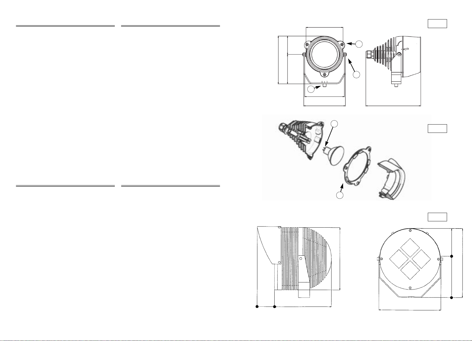
Die 300W- Beleuchtungen werden komplett
und installationsbereit geliefert (Abb. 3).
Bei anderen Spots (Abb.1 und 2) muß die
Lampe in den entsprechenden Verschluß ein-
geführt werden (für IR 300W, 230V,
Bajonettverschluß). Um diesen Arbeitsgang
durchzuführen, reicht es aus, wenn man die
Vorderseite durch die in Abbildung 1 Punkt
1 angezeigten Schrauben abmontiert und
die Kontakte des Beleuchtungskörpers in die
entsprechenden Sitze der Lampenfassung
einfügt (Abb. 2 Punkt 1). Nach Beendigung
m
dieses Arbeitsgangs die Vorderseite wieder
mit den Schrauben befestigen, wobei darauf
zu achten ist, daß die Dichtung korrekt mon-
tiert wird (Punkt 2).
Die Spots können an die Wand bzw. an
jede Art von stabiler Halterung befestigt wer-
den. Für die Montage den Bügel der
Beleuchtung durch eine dicke M8-Schraube
(mind. 6 mm Durchmesser) befestigen
(Abb. 1 Punkt 2). Die Neigung des
Lichtbündels durch die seitlichen Schrauben
(Abbildung 1 Punkt 3) regulieren; nach
Beendigung des Arbeitsgangs die seitlichen
Befestigungsschrauben wieder anziehen.
Die Massekabelverbindung für IR 50W,
230V, muß nicht wieder bewegt werden.
Falls kam das, die Leistung ausschalten und
das Kabel in seinem Sitz, beim Verwendung
der gelieferten Schraube oder eine gleich-
wertige M3 x 8mm, positionieren.
Bei der Installation sollten folgende Hinweise
auf jeden Fall beachtet werden:
1. Das Infrarotlicht kann nicht mit
bloßem Auge gesehen werden, kann
aber schwere Beschädigungen der
Netzhaut verursachen, wenn man sie
zu lange und zu nahe diesem Licht
aussetzt; daher sollten die Spots nur
bei Bedarf eingeschaltet werden.
2. Der Spotkörper dient auch als
Wärmeableiter und kann daher sehr
hohe Temperaturen erreichen. Aus
diesem Grund sollte er in
unzugänglichen Stellen installiert
werden.
3. Farbkameras sind normalerweise
unempfindlich gegenüber
Infrarotstrahlen; daher sollte man
Schwarzweißkameras
benutzen.
4. Die Leistungsfähigkeit des Spots hängt
in hohem Maße vom Ort, in dem
dieser eingesetzt wird, bei internen
Installationen und mit weißen
Wänden nimmt diese zu, bei
externen Installationen mit
IR20 spot
IR20 flood
IR20 wide
IR50 spot
IR50 flood
IR50 wide
IR50 flood
IR65 spot
IR65 flood
IR65 wide
IR300 spot
IR300 flood
IR300 wide
10°
40°
60
10°
40°
60°
40°
10°
40°
60°
8°
10°
20°
10
7
5
12
9
7
9
15
12
9
65
35
20
10°
40°
60
10°
40°
60°
40°
10°
40°
60°
10°
23°
40°
DISTANCE
(mètres)
FAISCEAU
VERTICAL
12
12
12
12
12
12
230
12
12
12
230
230
230
FAISCEAU
HORIZONTAL
MODELE VAC

8
Infrarotscheinwerfer
DEUTSCH
Grasflächen und dunklen Wänden im
Hintergrund hingegen nimmt sie
drastisch ab.
5. Einige Autoiris- Optiken können beim
Übergang vom Tag zur Nacht und
umgekehrt zu einer schlechten
Bildauflösung führen.
TECHNISCHEN DATEN
Spannung:
65/50/20W:
12VAC/VDC
50W: 230VAC
300W:
230VAC
Material:
Druckguss-Aluminiumm.
Varnishing:
Epoxypolyesterpulver.
Ausmaße:
65/50/20W:
L 108 X H 124,5 X P 146mm
300W:
L 217X H 233 X P 276mm
Gewicht:
65/50/20W:
0,9 Kg
300W:
5,3 Kg
Filter:
Optischen Filter von 850nm auf den
Kopfdeckel.
Schutz: IP65
Verbindungen:
65/50/20W:
Braun - Speisung
Blau – Speisung
50W, 230VAC:
Braun - Speisung
Blau – Speisung
Gelb/Grun – Masse
300W:
Braun - Speisung
Blau – Speisung
Gelb/Grun – Masse
IR20 spot
IR20 flood
IR20 wide
IR50 spot
IR50 flood
IR50 wide
IR50 flood
IR65 spot
IR65 flood
IR65 wide
IR300 spot
IR300 flood
IR300 wide
10°
40°
60
10°
40°
60°
40°
10°
40°
60°
8°
10°
20°
10
7
5
12
9
7
9
15
12
9
65
35
20
10°
40°
60
10°
40°
60°
40°
10°
40°
60°
10°
23°
40°
ABSTAND
(mt)
SENKR.
STRAHL
12
12
12
12
12
12
230
12
12
12
230
230
230
HORIZ.
STRAHL
MODELL VAC
This manual suits for next models
11
Table of contents
Languages:
Other Videotec Outdoor Light manuals
Popular Outdoor Light manuals by other brands

Costco
Costco SL-1227A-2PK instructions

Faro Barcelona
Faro Barcelona LE VITA 29691 instructions

DW Windsor
DW Windsor Kirium Pro Series installation instructions

Cooper Lighting
Cooper Lighting FE13PC Series instruction manual

Ingo Maurer
Ingo Maurer DEW DROPS TABLE instructions

STERNO HOME
STERNO HOME GL22921 instructions